e cv-p10lj - Sharp Australia Support - Sharp Corporation of Australia
e cv-p10lj - Sharp Australia Support - Sharp Corporation of Australia
e cv-p10lj - Sharp Australia Support - Sharp Corporation of Australia

You also want an ePaper? Increase the reach of your titles
YUMPU automatically turns print PDFs into web optimized ePapers that Google loves.
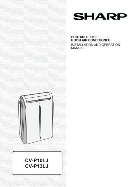
CV-P10LJ<br />
CV-P13LJ<br />
PORTABLE TYPE<br />
ROOM AIR CONDITIONER<br />
INSTALLATION AND OPERATION<br />
MANUAL<br />
ESPAÑO<br />
ENGLISH L
ENGLISH<br />
This manual explains the proper use <strong>of</strong> your new air conditioner. Please<br />
read this manual carefully before using the product. This manual should<br />
be kept in a safe place for handy reference.<br />
CONTENTS<br />
• USAGE CAUTIONS .....................................................................E-2<br />
• PRECAUTIONS ......................................................................E-3<br />
• LOCATION ...............................................................................E-3<br />
• INCLUDED ...............................................................................E-4<br />
• PART NAMES ..........................................................................E-5<br />
• INSTALL WINDOW PANEL ......................................................E-7<br />
• INSTALLATION AND REMOVAL OF EXHAUST HOSE .........E-11<br />
• PRE-OPERATION CHECKS ...................................................E-13<br />
• COOL MODE ...........................................................................E-15<br />
• DEHUMIDIFICATION MODE ...................................................E-15<br />
• FAN MODE ..............................................................................E-16<br />
• VENTILATION MODE ..............................................................E-16<br />
• TO CHANGE AIR FLOW DIRECTION .....................................E-17<br />
• PLASMACLUSTER OPERATION ............................................E-18<br />
• MEGA COOL OPERATION ......................................................E-19<br />
• SLEEP OPERATION................................................................E-19<br />
• TIMER OPERATION ................................................................E-20<br />
• MAIN UNIT OPERATION .........................................................E-21<br />
• DRAINAGE ..............................................................................E-22<br />
• MAINTENANCE .......................................................................E-22<br />
• BEFORE CALLING FOR SERVICE ........................................E-23<br />
E-1
USAGE CAUTIONS<br />
• Ventilate the room periodically during use, especially if using gas appliances.<br />
• Be sure to turn the unit <strong>of</strong>f and disconnect the power supply cord before performing any maintenance<br />
or cleaning.<br />
• Do not splash or pour water directly onto the unit.<br />
Water can cause electrical shock or equipment damage.<br />
• Drainage should be performed whenever moving the air conditioner.<br />
If any water remains in the tank, it may spill out while being moved.<br />
• Remove the window panel and close the window in the event <strong>of</strong> particularly adverse weather.<br />
Extremely adverse weather may cause water to leak in through the openings.<br />
• To ensure proper drainage, the drainage hose must have no kinks or be on a different level during<br />
dehumidifi cation mode.<br />
The drained water may spill out into the room.<br />
• The temperature around the drainage hose must not be below freezing point when used.<br />
Drained water may freeze inside the hose, causing water inside the unit to overfl ow into the room.<br />
• Do not block the exhaust air outlet with obstacles.<br />
Cooling performance may be reduced or stop completely .<br />
NOTES ON OPERATION<br />
• Allow 3 minutes for the compressor to restart cooling.<br />
If you turn the air conditioner <strong>of</strong>f and immediately restart it, allow three minutes for the compressor to restart<br />
cooling. There is an electronic device in the unit that keeps the compressor turned <strong>of</strong>f for three minutes for<br />
safety.<br />
• In the event <strong>of</strong> a power failure during use, allow 3 minutes before restarting the unit.<br />
After power is reinstated, restart the air conditioner. If the power was <strong>of</strong>f for less than three minutes, be sure<br />
to wait at least three minutes before restarting the unit. If you restart the air conditioner within three minutes,<br />
a protective device in the unit may cause the compressor to shut <strong>of</strong>f. This protective device will prevent cooling<br />
for about 5 minutes. Any previous settings will be canceled and the unit will return to its initial settings.<br />
• Low temperature operation: Is your unit freezing up?<br />
Freezing may occur when the unit is set close to 18°C in low ambient temperature conditions, especially at<br />
night.<br />
In these conditions, a further temperature drop may cause the unit to freeze.<br />
Setting the unit to a higher temperature will prevent it from freezing.<br />
• Dehumidifi cation mode increases room temperature.<br />
The unit generates heat during dehumidifi cation mode and the room temperature will rise. Warm air will be<br />
blown out from the Exhaust air outlet, but this is normal and does not indicate a problem with the unit.<br />
• This air conditioner blows the warm air generated by the unit outside the room via the exhaust hose<br />
while in cool mode.<br />
Accordingly, the same amount <strong>of</strong> air as that blown out will enter the room from outside through any<br />
openings into the room.<br />
• When cooling operation is performed at high humidity conditions, water tank inside the unit may frequently<br />
become full.<br />
When water tank inside the unit is full, the unit stops operating and TIMER, OPERATION and MEGA COOL<br />
lamps will blink. In this case, perform drainage to drain out water within the unit.<br />
E-2<br />
ENGLISH
PRECAUTIONS<br />
OPERATING CONDITIONS<br />
• The air conditioner must be operated within the temperature range indicated below.<br />
MODE Room temperature<br />
Cool 18°C ~ 35°C<br />
Dehumidifi cation 15°C ~ 35°C<br />
• A built-in safety device may cut <strong>of</strong>f operation if the temperature exceeds these limits.<br />
• When cooling operation is performed at high room temperature, the fan may run at a<br />
slower speed.<br />
ENERGY EFFICIENCY TIPS<br />
• Avoid direct sunlight.<br />
Close blinds, drapes or shades to keep out direct sunlight while in cooling mode.<br />
• Keep the fi lter clean.<br />
Keeping the fi lter clean greatly aids effi cient operation.<br />
A dirty fi lter blocks the fl ow <strong>of</strong> air, making your air conditioner work harder and less effi -<br />
ciently.<br />
• Turn <strong>of</strong>f unnecessary lights.<br />
Your air conditioner must remove the heat produced by your lights or other heat-producing<br />
appliances. Turn <strong>of</strong>f any lights or appliances that are not in use.<br />
• Turn <strong>of</strong>f the air conditioner when no one is home.<br />
Use only when necessary. The less time the air conditioner is used, the lower the running<br />
costs.<br />
LOCATION<br />
• The air conditioner should be placed on a fi rm foundation to minimize noise and vibration.<br />
For safe and secure positioning, place the unit on a smooth, level fl oor strong enough to<br />
support the unit.<br />
• The unit has casters to aid placement, but it should only be rolled on smooth, fl at surfaces.<br />
Use caution when rolling on carpet surfaces. Do not attempt to roll the unit over<br />
objects.<br />
• The unit must be placed within reach <strong>of</strong> a properly rated grounded socket.<br />
• Never place any obstacles around the air inlet or outlet <strong>of</strong> the unit.<br />
• Allow at least 12" (30cm) <strong>of</strong> space from the wall for effi cient air-conditioning.<br />
MIN.12"<br />
(30cm)<br />
MIN.12"<br />
(30cm)<br />
E-3<br />
MIN.12"<br />
(30cm)
INCLUDED<br />
Exhaust hose<br />
Window exhaust<br />
adapter 1<br />
Exhaust hose<br />
adapter<br />
Extension panel<br />
1<br />
1<br />
1<br />
3<br />
Rain guard<br />
Insect guard net<br />
Foam seal A<br />
Foam seal B<br />
(adhesive type) 1<br />
Bracket<br />
Screw<br />
2<br />
1<br />
1<br />
1<br />
8<br />
Manual<br />
Remote control<br />
Battery<br />
(AAA.1.5V) 2<br />
SUGGESTED TOOLS FOR WINDOW PANEL INSTALLATION<br />
1. Screwdriver(medium size Phillips) 2. Tape measure or ruler 3. Knife or scissors<br />
4. Saw (In the event that the window panel needs to be cut down in size because the window is too narrow for<br />
direct installation.)<br />
E-4<br />
1<br />
1
PART NAMES<br />
FRONT VIEW<br />
REAR VIEW<br />
NOTE: Actual unit might vary slightly from above illustration.<br />
E-5<br />
1<br />
2<br />
3<br />
4<br />
5<br />
6<br />
7<br />
8<br />
9<br />
0<br />
0<br />
q<br />
w<br />
e<br />
r<br />
t<br />
y<br />
u<br />
i<br />
o<br />
p<br />
a<br />
s<br />
1 Air Outlet<br />
2 Vertical louvers<br />
3 Horizontal louvers<br />
4 POWER Button<br />
5 Remote control signal<br />
receiver window<br />
6 OPERATION Lamp (red)<br />
7 TIMER Lamp (orange)<br />
8 MEGA COOL Lamp<br />
(green)<br />
9 PLASMACLUSTER<br />
Lamp (blue)<br />
0 Air inlet<br />
q Insect guard net<br />
w Window exhaust adapter<br />
e<br />
Exhaust hose<br />
r Remote control hook<br />
t<br />
Remote control hook<br />
Air fi lter<br />
y Exhaust hose adapter B<br />
u Cover<br />
i Grille<br />
o Air inlet<br />
p Drainpipe and stopcock<br />
a Power plug<br />
s Casters(4)
REMOTE CONTROL<br />
REMOTE CONTROL DISPLAY<br />
y<br />
u<br />
i<br />
o<br />
1<br />
2<br />
3<br />
4<br />
5<br />
6<br />
7<br />
8<br />
9<br />
0<br />
q<br />
w<br />
e<br />
r<br />
t<br />
p<br />
a<br />
s<br />
d<br />
1 Transmitter<br />
2 Display<br />
3 POWER Button<br />
4 LIGHTS Button<br />
5 TEMPERATURE Button<br />
6 PLASMACLUSTER Button<br />
7 SLEEP Button<br />
8 MODE Button<br />
9 ON TIMER Button<br />
0 FAN Button<br />
q OFF TIMER Button<br />
w CANCEL Button<br />
e LOUVERS Button<br />
r RESET Button<br />
t MEGA COOL Button<br />
y MODE SYMBOLS<br />
E-6<br />
: COOL : DEHUMIDIFICATION<br />
: FAN : VENTILATION<br />
u MEGA COOL SYMBOL<br />
i PLASMACLUSTER SYMBOL<br />
o FAN SPEED SYMBOLS<br />
: AUTO : Quiet<br />
: Low : High<br />
p TEMPERATURE AND TIMER COUNT<br />
DOWN INDICATOR<br />
a TRANSMITTING SYMBOL<br />
s ON TIMER / OFF TIMER SYMBOL<br />
d SLEEP SYMBOL<br />
ENGLISH
INSTALL WINDOW PANEL<br />
Installation in a double-hung sash window<br />
(See page 9 for installation in a sliding sash window. )<br />
1<br />
2<br />
3<br />
4<br />
Connect the rain guards to the insect<br />
guard net.<br />
Insert all three projections on each rain<br />
guard into the holes in the insect guard net.<br />
Side “A” will now be uppermost, as indicated<br />
in the diagram.<br />
Attach the guard combined above to the<br />
window panel<br />
Push the insect guard net fi rmly to ensure<br />
that its four projections fi t into the holes in<br />
the window panel.<br />
Side “A” will now be at the top, as indicated<br />
in the diagram.<br />
Cut the foam seal A (adhesive type) to<br />
the proper length and attach it to the<br />
window stool.<br />
Attach the window panel to the window<br />
stool.<br />
If the inner width <strong>of</strong> the window is between<br />
22" (559mm) and 24" (609mm)<br />
inclusive.<br />
The window panel cannot be installed in<br />
windows less than 22" (559mm) wide,<br />
as you will be unable to shut the exhaust<br />
cover.<br />
(1) Remove the adjustment panel from<br />
the window panel, and cut the window<br />
panel to the same width as the window.<br />
(2) Open the window sash and place the<br />
window panel on the window stool<br />
(3) Secure the window panel to the window<br />
stool with 2 screws.<br />
E-7<br />
Insect guard<br />
net<br />
Projection<br />
"A"<br />
22"~ 24"<br />
Hole<br />
Projection<br />
Rain guard<br />
"A"<br />
Window panel<br />
Cut<br />
Window stool<br />
Foam seal A<br />
(adhesive type)<br />
Window panel
5<br />
6<br />
7<br />
8<br />
If the inner width <strong>of</strong> the window is<br />
between 24" (609mm) and 36.8"<br />
(934mm) inclusive.<br />
(1) Open the window sash and place the<br />
window panel on the window stool.<br />
(2) Slide the adjustment panel to fi t the<br />
window frame width.<br />
(3) Secure the window panel to the stool<br />
with 3 screws.<br />
If the inner width <strong>of</strong> the window is between<br />
36.8" (934mm) and 48" (1219mm)<br />
inclusive.<br />
(1) Attach the extension panel to the<br />
adjustment panel.<br />
(2) Open the window sash and place the<br />
window panel on the window stool.<br />
(3) Slide the adjustment and extension<br />
panels to fi t the window frame width.<br />
(4) Secure the window panel to the window<br />
stool with 4 screws.<br />
Cut the foam seals (adhesive type) A<br />
and B to the proper length and attach it<br />
to the window panel.<br />
Attach foam seal A to the window panel and<br />
extension panel, and attach foam seal B to<br />
the adjustment panel.<br />
Close the window sash securely against<br />
the Window panel.<br />
Cut the foam seal to an appropriate<br />
length and seal the opening between the<br />
top <strong>of</strong> the inner window sash and the<br />
outer window sash.<br />
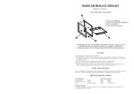
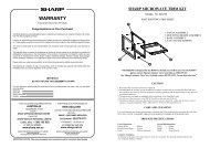
Attach a bracket with the screw.<br />
E-8<br />
36.8"~48"<br />
24"~36.8"<br />
Extension panel<br />
Adjustment panel<br />
Foam seal A<br />
(adhesive type)<br />
Bracket
INSTALL WINDOW PANEL<br />
Installation in a sliding sash window<br />
1<br />
2<br />
3<br />
4<br />
Connect the rain guards to the insect<br />
guard net.<br />
Insert all three projections on each rain<br />
guard into the holes in the insect guard<br />
net.<br />
Side “A” will now be uppermost, as<br />
indicated in the diagram.<br />
Attach the guard combined above to the<br />
window panel.<br />
Push the insect guard net fi rmly to ensure<br />
that its four projections fi t into the holes in<br />
the window panel.<br />
Side “A” will now be at the top, as indicated<br />
in the diagram, when it is installed in the<br />
window.<br />
Cut the foam seal A (adhesive type) to<br />
the proper length and attach it to the<br />
window frame.<br />
Install the window panel into the window<br />
frame.<br />
If the inner height <strong>of</strong> the window is<br />
between 22" (559mm) and 24" (609mm)<br />
inclusive.<br />
The window panel cannot be installed in<br />
windows less than 22" (559mm) high, as<br />
you will be unable to shut the exhaust<br />
cover.<br />
(1) Remove the adjustment panel from the<br />
window panel, and cut the window panel<br />
to the same height as the window.<br />
(2) Open the window sash and place the<br />
window panel on the window frame.<br />
(3) Secure the window panel to the window<br />
frame with 2 screws.<br />
E-9<br />
Insect guard net<br />
Hole<br />
Projection<br />
Projection<br />
Window<br />
panel<br />
Cut<br />
"A"<br />
Rain guard<br />
Window panel<br />
"A"<br />
Foam seal A<br />
(adhesive type)<br />
22"~24"
5<br />
6<br />
7<br />
8<br />
If the inner height <strong>of</strong> the window is<br />
between 24" (609mm) and 36.8"<br />
(934mm) inclusive.<br />
(1) Open the window sash and place the<br />
window panel on the window frame.<br />
(2) Slide the adjustment panel to fi t the<br />
window frame height.<br />
(3) Secure the window panel to the window<br />
frame with 3 screws.<br />
If the inner height <strong>of</strong> the window is between<br />
36.8" (934mm) and 48" (1219mm)<br />
inclusive.<br />
(1) Attach the extension panel to the<br />
adjustment panel.<br />
(2) Open the window sash and place the<br />
window panel on the window frame.<br />
(3) Slide the adjustment and extension<br />
panels to fi t the window frame height.<br />
(4) Secure the window panel to the window<br />
frame with 4 screws.<br />
Cut the foam seals (adhesive type) A and<br />
B to the proper length and attach them<br />
to the window panel.<br />
Attach foam seal A to the window panel and<br />
extension panel, and attach foam seal B to<br />
the adjustment panel.<br />
Close the window sash securely against<br />
the Window panel.<br />
Cut the foam seal to an appropriate<br />
length and seal the opening between the<br />
side <strong>of</strong> the inner window sash and the<br />
outer window sash.<br />
Attach a bracket with the screw.<br />
E-10<br />
Adjustment<br />
panel<br />
Extension panel<br />
Foam seal A<br />
(adhesive type)<br />
Bracket<br />
24"~36.8"<br />
36.8"~48"
The exhaust hose must be installed or removed in accordance with the usage mode.<br />
MODE EXHAUST HOSE<br />
COOL, FAN, VENTILATION, DEHUMIDIFICATION with no container Install<br />
DEHUMIDIFICATION with container Remove<br />
Installation <strong>of</strong> the exhaust hose<br />
1<br />
2<br />
3<br />
INSTALLATION AND REMOVAL OF EXHAUST HOSE<br />
Attach the window exhaust adapter to<br />
the exhaust hose.<br />
Extend one end <strong>of</strong> the exhaust hose<br />
and insert it into the window exhaust<br />
adapter, and turn it (approx. three times)<br />
until it stops.<br />
Make sure they are securely attached<br />
afterwards.<br />
Attach the exhaust hose adapter to<br />
the unit.<br />
Insert the two projections on the exhaust<br />
hose adapter into the two holes<br />
on the unit, and fi rmly attach them to<br />
each other.<br />
Slide and open the exhaust cover on<br />
the window panel, and attach the window<br />
exhaust adapter.<br />
Surface <strong>of</strong> window exhaust adapter<br />
marked "TOP" should be at the top<br />
when it is installed in a double-hung<br />
sash window.<br />
Surface <strong>of</strong> window exhaust adapter<br />
marked "TOP" should be on the window<br />
frame side when it is installed in a<br />
sliding sash window.<br />
E-11<br />
Extend<br />
Exhaust hose<br />
The exhaust hose should be as short as possible for operational effi ciency;<br />
however, it must not be twisted or bent.<br />
Unacceptable Acceptable Acceptable<br />
Window exhaust<br />
adapter<br />
Projection<br />
Hole<br />
"TOP"
Removal <strong>of</strong> the exhaust hose<br />
1<br />
2<br />
Remove the window exhaust adapter.<br />
Pull out and remove the window exhaust<br />
adapter by pushing down two “PUSH”<br />
markings, and slide and close the exhaust<br />
cover in the window panel.<br />
Remove the exhaust hose adapter from<br />
the unit.<br />
Lift up and remove the exhaust hose<br />
adapter from the unit by pushing down on<br />
the two projections.<br />
E-12<br />
Projection<br />
"PUSH"
PRE-OPERATION CHECKS<br />
LOADING BATTERIES Use two AAA (R03) batteries.<br />
1<br />
2<br />
3<br />
4<br />
Remove the battery cover at the<br />
back <strong>of</strong> the remote control.<br />
Insert batteries into the compartment,<br />
making sure the ±<br />
and — polarities are correctly<br />
aligned.<br />
• Lines will appear on the display<br />
when batteries are properly installed.<br />
Reattach the battery cover.<br />
Press the RESET button using<br />
a thin pointed implement.<br />
NOTES:<br />
• The battery should last approximately one year under normal use.<br />
• When replacing the batteries, always change both batteries at the same time,<br />
and make sure they are the same type.<br />
• If the remote control does not operate normally after replacing the batteries,<br />
press the RESET button using a thin pointed implement.<br />
• If you will not be using the unit for a prolonged period, remove the batteries from<br />
the remote control.<br />
E-13<br />
Battery cover
HOW TO USE THE REMOTE CONTROL<br />
Point the remote control towards<br />
the units signal receiver window<br />
and press the desired button. A<br />
beep will sound when the unit receives<br />
the signal.<br />
• Make sure nothing, such as curtains,<br />
blocks the signal receiver window.<br />
• The remote control operates up to<br />
23 feet (7 meters) away.<br />
CAUTION<br />
• Do not expose the signal receiver window to direct sunlight. This may adversely<br />
affect its operation. If necessary, close the curtains to block out the sunlight.<br />
• Use <strong>of</strong> a fl uorescent lamp in the same room may interfere with transmission <strong>of</strong> the<br />
signal.<br />
• The unit may be affected by signals emitted from other remote controllers for televisions,<br />
VCRs or other equipment used in the same room.<br />
• Do not leave the remote control exposed to direct sunlight or near a heater. Protect<br />
the remote control from moisture and shock which can discolor or damage it.<br />
To prevent the remote control from<br />
being misplaced, hook it to the unit<br />
when not in use.<br />
When attached, to remove the remote<br />
control from the unit, lift the remote<br />
control up slightly and pull it out.<br />
E-14<br />
Remote control hook<br />
ENGLISH
COOL MODE<br />
Stopcock<br />
Drainpipe<br />
2<br />
3<br />
1<br />
4<br />
Ensure that the stopcock is securely attached the<br />
drainpipe.<br />
1<br />
2<br />
3<br />
4<br />
Press the MODE button to select COOL<br />
mode.<br />
COOL DEHUM FAN VENT<br />
Press the POWER button to start operation.<br />
• The red OPERATION lamp on the unit will light.<br />
Press the TEMPERATURE button to set<br />
the desired temperature.<br />
• The temperature can be set within the range <strong>of</strong><br />
18°C to 30°C.<br />
Press the FAN button to set the desired<br />
fan speed.<br />
AUTO QUIET LOW HIGH<br />
TO TURN OFF<br />
DEHUMIDIFICATION MODE<br />
In this mode, the air conditioner dehumidifi es the room.<br />
Press the POWER button again.<br />
• The red OPERATION lamp on the unit will turn <strong>of</strong>f.<br />
Ensure that the stopcock is securely attached the drainpipe.<br />
2<br />
1<br />
1<br />
2<br />
Press the MODE button to select DEHU-<br />
MIDIFICATION mode.<br />
COOL DEHUM FAN VENT<br />
Press the power button to start operation.<br />
• The red OPERATION lamp on the unit will light.<br />
• The temperature cannot be set.<br />
• The fan speed is preset to AUTO and cannot be<br />
changed.<br />
TO TURN OFF<br />
Press the POWER button again.<br />
• The red OPERATION lamp on the unit will turn <strong>of</strong>f.<br />
E-15
FAN MODE<br />
In this mode, the air conditioner simply circulates the air without cooling it.<br />
Ensure that the stopcock is securely attached to the drainpipe.<br />
2<br />
1<br />
3<br />
VENTILATION MODE<br />
In this mode, the air conditioner ventilates the air to outdoors.<br />
2<br />
1<br />
3<br />
1<br />
2<br />
3<br />
Press the MODE button to select FAN mode.<br />
COOL DEHUM FAN VENT<br />
Press the POWER button to start operation.<br />
• The red OPERATION lamp on the unit will light.<br />
• The temperature cannot be set.<br />
Press the FAN button to set the desired fan<br />
speed.<br />
QUIET LOW HIGH<br />
TO TURN OFF<br />
Press the POWER button again.<br />
• The red OPERATION lamp on the unit will turn <strong>of</strong>f.<br />
Ensure that the stopcock is securely attached to the drainpipe.<br />
1<br />
2<br />
3<br />
Press the MODE button to select VENT mode.<br />
COOL DEHUM FAN VENT<br />
Press the POWER button to start operation.<br />
• The red OPERATION lamp on the unit will light.<br />
• The temperature cannot be set.<br />
Press the FAN button to set the desired fan<br />
speed.<br />
• Although the louvers are closed and no air blows<br />
out into the room, the external ventilation fan<br />
speed changes.<br />
QUIET LOW HIGH<br />
TO TURN OFF<br />
Press the POWER button again.<br />
• The red OPERATION lamp on the unit will turn <strong>of</strong>f.<br />
E-16
TO CHANGE AIR FLOW DIRECTION<br />
UP / DOWN AIR FLOW DIRECTION<br />
1<br />
2<br />
1<br />
2<br />
LEFT / RIGHT AIR FLOW DIRECTION<br />
Press the LOUVERS button on the remote<br />
control.<br />
• The horizontal louvers will swing continuously.<br />
Press the LOUVERS button again when<br />
the horizontal louvers are at the desired<br />
position.<br />
• The horizontal louvers will stop moving.<br />
• The adjusted position will be memorized and<br />
the same position will be set automatically<br />
when operated the next time.<br />
NOTE<br />
• During VENTILATION mode, UP/DOWN air fl ow<br />
direction cannot be changed.<br />
Horizontal louvers<br />
Vertical louvers<br />
Hold the vertical louver as shown in the diagram<br />
and adjust the air fl ow direction.<br />
CAUTION<br />
Never attempt to adjust the horizontal louvers manually.<br />
• Manual adjustment <strong>of</strong> the horizontal louvers can cause the unit to malfunction when the remote<br />
control is used for adjustment.<br />
• When the horizontal louvers are positioned at the lowest position in the COOL or DEHUMIDIFI-<br />
CATION mode for an extended period <strong>of</strong> time, condensation may result.<br />
Do not adjust the vertical louvers to the extreme left or right in the COOL mode with the<br />
fan speed set to "QUIET ( )" for an extended period <strong>of</strong> time.<br />
Condensation may form on the louvers.<br />
E-17
PLASMACLUSTER OPERATION<br />
Plasmacluster ions released into the room will reduce some airborne mold.<br />
1<br />
1<br />
Press the PLASMACLUSTER button during<br />
operation.<br />
• The remote control will display “ ”.<br />
• The blue PLASMACLUSTER lamp on the unit will<br />
light.<br />
TO CANCEL<br />
Press the PLASMACLUSTER button again.<br />
• The PLASMACLUSTER lamp on the unit will turn<br />
<strong>of</strong>f.<br />
NOTES:<br />
• Use <strong>of</strong> the PLASMACLUSTER function will be<br />
memorized and it will be activated the next time you<br />
turn on the air conditioner.<br />
• To turn <strong>of</strong>f the PLASMACLUSTER Lamp, press the<br />
LIGHTS button.<br />
• PLASMACLUSTER operation cannot be set during<br />
VENTILATION mode.<br />
E-18<br />
ENGLISH
MEGA COOL OPERATION<br />
In this operation, the air conditioner fan works at extra high speed with a setting<br />
temperature <strong>of</strong> 15°C.<br />
1<br />
1<br />
Press the MEGA COOL button during cooling<br />
mode.<br />
• The remote control will display " " .<br />
• The temperature display will go <strong>of</strong>f.<br />
• The green MEGA COOL lamp on the unit will light.<br />
TO CANCEL<br />
Press the MEGA COOL button again.<br />
• MEGA COOL operation is also cancelled when the<br />
mode is changed, or when the unit is turned <strong>of</strong>f.<br />
• The green MEGA COOL lamp on the unit will turn<br />
<strong>of</strong>f.<br />
NOTES:<br />
• You cannot set the temperature or fan speed during MEGA COOL operation.<br />
• The fan returns to the HIGH speed setting after the unit has run for 30 minutes in MEGA<br />
COOL mode.<br />
• The extra high fan speed may automatically slow down to protect the unit.<br />
SLEEP OPERATION<br />
When SLEEP operation is set, the temperature setting is automatically adjusted to<br />
prevent the room from becoming too cold.<br />
1<br />
1<br />
Press the SLEEP button during cooling<br />
mode.<br />
• The remote control displays “ ”.<br />
• The orange TIMER lamp on the unit will light.<br />
• The unit will stop operating after 8 hours.<br />
• The fan speed setting is set to AUTO.<br />
TO CANCEL<br />
NOTES:<br />
• One hour after the SLEEP operation is started, the<br />
temperature setting rises by 1˚C and after another<br />
hour it rises by an additional 1˚C. Temperature display<br />
on the remote control will not change from its original<br />
setting.<br />
• SLEEP operation and MEGA COOL operation can<br />
not be used together.<br />
• The OFF TIMER, ON TIMER and SLEEP operation<br />
can not be set together.<br />
Only the most recent settings will be used.<br />
Press the SLEEP button.<br />
• The orange TIMER lamp on the unit will turn <strong>of</strong>f.<br />
• SLEEP operation is also cancelled when the mode<br />
is changed, or when the unit is turned <strong>of</strong>f.<br />
E-19<br />
1hour<br />
8hours<br />
1hour<br />
1˚C<br />
Start <strong>of</strong><br />
SLEEP operation<br />
1˚C<br />
Unit shuts <strong>of</strong>f
TIMER OPERATION<br />
ON TIMER<br />
OFF TIMER<br />
CANCEL<br />
CANCEL<br />
1<br />
1<br />
Press the ON TIMER button.<br />
1 • The time setting will change as you press the button<br />
as follows. Hold the button down to speed through the<br />
settings.<br />
0.5h 1.0h 1.5h 10h 11h 12h<br />
• The orange TIMER lamp on the unit will light.<br />
• The time setting will count down to show the remaining<br />
time.<br />
Select the mode, temperature, fan speed setting and<br />
PLASMACLUSTER operation as desired.<br />
• When the temperature is set with the ON TIMER, the<br />
temperature will show in the display for 5 seconds and<br />
then return to the time display.<br />
• If you do not change the setting, the unit will operate using<br />
the most recent setting.<br />
TO CANCEL TIMER<br />
Press the CANCEL button.<br />
• The orange TIMER lamp on the unit will turn <strong>of</strong>f.<br />
Press the OFF TIMER button and set the time<br />
1 as desired.<br />
• The time setting will change as you press the button<br />
as follows. Hold the button down to speed through<br />
the settings.<br />
0.5h 1.0h 1.5h 10h 11h 12h<br />
• The orange TIMER lamp on the unit will light.<br />
• The time setting will count down to show the remaining<br />
time.<br />
TO CANCEL TIMER<br />
Press the CANCEL button.<br />
• The orange TIMER lamp on the unit will turn <strong>of</strong>f.<br />
NOTES<br />
• Timer duration can be set from a minimum <strong>of</strong> half an hour to a maximum <strong>of</strong> 12 hours.<br />
Up to 9.5 hours, you can set in half-hour increments and from 10 to 12 hours, in 1-hour increments.<br />
• The latest time setting will be memorized and will appear on the remote control display the next time you<br />
set the OFF TIMER or ON TIMER.<br />
• The OFF TIMER and ON TIMER can not be set together.<br />
Only the most recent TIMER setting will be valid.<br />
• If a power failure occurs while the OFF TIMER or ON TIMER is set, the TIMER setting will be cancelled and<br />
will not be retrieved even after the power is restored.<br />
E-20<br />
ENGLISH
MAIN UNIT OPERATION<br />
Use this mode when the remote control is not available.<br />
DRAINAGE<br />
Prepare for drainage and drain out water within the unit in the following cases.<br />
• When the unit stops operating and the TIMER, OPERATION and MEGA COOL lamps are<br />
blinking, the water tank is full and need to be drained.<br />
• When the unit is not used for a long time.<br />
1<br />
2<br />
3<br />
1<br />
1<br />
Unplug the power plug and move the unit to a<br />
drain or outside.<br />
Remove the stopcock from the drainpipe, and<br />
drain water within the unit.<br />
Replace the stopcock to the drainpipe.<br />
Press the POWER button on the unit.<br />
• The red OPERATION lamp on the unit will<br />
light.<br />
• If the unit has not been unplugged since it<br />
was last operated, it will resume operation at<br />
its last settings.<br />
• If the unit has been unplugged since it was<br />
last operated, it will resume operation in the<br />
cooling mode, set at 20˚C. The fan speed set<br />
to AUTO.<br />
TO TURN OFF<br />
Press the POWER button again.<br />
• The red OPERATION lamp on the unit will turn<br />
<strong>of</strong>f.<br />
E-21<br />
Stopcock<br />
Drainpipe
MAINTENANCE<br />
Be sure to disconnect the power from the wall socket before performing any maintenance.<br />
CLEANING THE FILTER<br />
If the fi lter is clogged with dust, the airfl ow will be reduced, resulting in poor cooling<br />
performance. The fi lter should be cleaned every two weeks.<br />
Air fi lter<br />
Grille<br />
Air inlet fi lter<br />
AIR FILTER<br />
REMOVE THE FILTER<br />
1 • Gently pull the filter handle to the right and<br />
slide the fi lter out <strong>of</strong> the unit.<br />
CLEAN THE FILTER<br />
2 • Use a vacuum cleaner to remove any dust. If<br />
the filter is very dirty, wash it with detergent<br />
and rinse carefully with clean water. Dry the<br />
fi lter in the shade before reinstalling them.<br />
REINSTALL THE FILTER<br />
3 • Hold the fi lter handle and gently push the fi lter<br />
back into place.<br />
Never operate the unit without the fi lter. Doing<br />
so may result in serious damage to the unit.<br />
AIR INLET FILTER (For single-duct type)<br />
Remove the grille and clean the air inlet filter<br />
with a vacuum cleaner.<br />
CLEANING THE UNIT AND THE REMOTE CONTROL<br />
Wipe them with a s<strong>of</strong>t, dry cloth or with a cloth moistened with a mild soap. Carefully remove<br />
any residue by wiping with a damp cloth and dry completely.<br />
Avoid splashing water onto the unit. Water can dangerously damage the electrical insulation.<br />
Never use harsh chemicals or abrasive cleaners on any part <strong>of</strong> the unit. To avoid damaging<br />
the unit, do not use hot water (120°F/50°C or hotter) when cleaning.<br />
MAINTENANCE AFTER AIR CONDITIONER SEASON<br />
1 Perform drainage to drain out water within the unit.<br />
2<br />
Operate the unit in the FAN or VENTILATION mode for about half a day to<br />
thoroughly dry inside the unit.<br />
3<br />
Clean the fi lters, then reinstall them.<br />
E-22<br />
ENGLISH
BEFORE CALLING FOR SERVICE<br />
If the unit appears to be malfunctioning, check the following points before calling<br />
for a service.<br />
AIR CONDITIONER DOES NOT OPERATE AT ALL<br />
• Is the unit plugged in or is the plug loose?<br />
• Has the fuse blown or is the circuit breaker tripped?<br />
• Did you restart the unit within 3 minutes <strong>of</strong> a power failure?<br />
If the power was <strong>of</strong>f for less than 3 minutes when, you restarted the air conditioner, a protective<br />
device may cause the compressor to shut <strong>of</strong>f, preventing cooling for about 5 minutes.<br />
• Are the OPERATION, TIMER and MEGA COOL lamps blinking?<br />
The water tank inside the unit is full. It must be drained.<br />
• Check the power plug.<br />
AIR CONDITIONER DOES NOT COOL PROPERLY<br />
• Is it set to FAN, DEHUMIDIFICATION or VENTILATION mode?<br />
Cooling does not take place in these modes. Change the MODE setting.<br />
• Is the fi lter clogged with dust?<br />
Clean the fi lter.<br />
• Is the cooling coil frozen?<br />
No air will blow out if the cooling coil is frozen.<br />
Run the air conditioner in FAN mode with the fan speed set to "HIGH" until all ice dissipates.<br />
• Is the temperature set properly?<br />
• Is the window exposed to direct sunlight?<br />
Close the curtains or blinds to minimize solar energy heating the room.<br />
• Is the exhaust hose too long?<br />
For effi cient operation, make the hose as short as possible. The exhaust hose must not be twisted<br />
or bent.<br />
SOUNDS<br />
• The unit may seem rather loud for the fi rst 2 to 3 minutes when the unit is turned on. This is the<br />
sound <strong>of</strong> the compressor starting-up and is perfectly normal.<br />
• A s<strong>of</strong>t, swishing noise can be heard immediately after the unit is turned on or <strong>of</strong>f, and also during<br />
operation. This is the sound <strong>of</strong> the refrigerant fl owing inside the unit.<br />
• A low buzzing noise is emitted when the unit is generating Plasmacluster ions.<br />
• This air conditioner evaporates water condensed during cooling operation within the unit through<br />
the exhaust air outlet. Although water fl owing sound may be heard, this is normal.<br />
• An audible gurgling sound may be heard when the unit is operated on a gently sloping<br />
fl oor. Place the unit on a level fl oor.<br />
TIMER DOES NOT WORK PROPERLY<br />
• If a power failure occurs while the TIMER is set, the TIMER setting will be cancelled and will not<br />
be retrieved even after the power is restored. This is normal for this unit.<br />
THE UNIT FAILS TO REACT TO THE REMOTE CONTROL SIGNAL<br />
• Check the batteries in the remote control. Replace if necessary.<br />
• Try to send the signal again with the remote control pointed directly at the unit’s signal receiver<br />
window.<br />
• Check whether the remote control batteries are installed with the polarities properly aligned.<br />
THE DISCHARGED AIR HAS AN ODOR<br />
• Plasmacluster ion generator emit small traces <strong>of</strong> ozone which may produce an odor. These<br />
ozone emissions are below safety levels.<br />
E-23
Sr<br />
No<br />
Technical Specifications<br />
Parameter Unit Value<br />
1 Model CV-P10LJ<br />
2<br />
Power<br />
Supply<br />
Rated Voltage V~ 220-240<br />
Rated Frequency Hz 50<br />
Phases 1<br />
3 Cooling Capacity W 2930<br />
4 Cooling Power Input W 1100<br />
5 Cooling Power Current A 4.80<br />
6 Rated Input W 1250<br />
7 Rated Current A 5.80<br />
8 Air Flow Volume(H/M/L) m 3 /h 350/260/180<br />
9 Dehumidifying Volume L/h 1<br />
10 EER W/W 2.66<br />
11 Application Area m 2<br />
14~20<br />
12 Climate Type T1<br />
13 Isolation I<br />
14 Moisture Protection IP24<br />
15<br />
16<br />
Permissible Excessive Operating Pressure<br />
for the Discharge Side<br />
Permissible Excessive Operating Pressure<br />
for the Suction Side<br />
MPa 3.8<br />
MPa 1<br />
17 Throttling Method Capillary<br />
18 Fuse A 3.15<br />
19 Operation Temp ℃ 16ºC~30ºC<br />
20 Ambient Temp (Cooling) ℃ 10ºC~35ºC<br />
21 Sound Pressure Level (H/M/L) dB (A) 56/54/52<br />
22 Sound Power Level (H/M/L) dB (A) 66/65/62<br />
23 Dimension (WXHXD) mm 500×830×450<br />
24 Dimension <strong>of</strong> Carton Box (L/W/H) mm 578x532x862<br />
25 Dimension <strong>of</strong> Package (L/W/H) mm 581x535x877<br />
26 Net Weight kg 41<br />
27 Gross Weight kg 48<br />
E-24
28 Refrigerant R410A<br />
29 Refrigerant Charge kg 0.67<br />
30 Compressor LANDA COMPRESSOR<br />
31 Compressor Model QXA-B102T130<br />
32 Compressor Oil RB68EP<br />
Compressor<br />
33 Compressor Type Rotary<br />
34 L.R.A. A 19.00<br />
35 Compressor RLA A 3.90<br />
36<br />
Compressor Power Input W 850<br />
37 Fan Type Centrifugal<br />
38 Diameter Length(DXL) mm φ227 X 109<br />
39 Fan Motor Speed(H/ML) r/min 950/750/500<br />
40 Output <strong>of</strong> Fan Motor W 40<br />
41 Fan Motor RLA A 0.46<br />
42 Fan Motor Capacitor<br />
Evaporator<br />
μF 3.5<br />
43 Form Aluminum Fin-copper Tube<br />
44 Pipe Diameter mm φ7<br />
45 Row-fin Gap mm 3-1.6<br />
46 Coil Length (LXDXW) mm 348.5 X38.1X286<br />
47 Swing Motor Model MP28GA<br />
48<br />
Output <strong>of</strong> Swing Motor W 2<br />
49 Fan Type Centrifugal<br />
50 Fan Diameter mm φ227 X 109<br />
51 Form Aluminum Fin-copper Tube<br />
52 Pipe Diameter mm φ7<br />
53 Rows-fin Gap<br />
Condenser<br />
mm 3-1.6<br />
54 Coil Length (LXDXW) mm 348.5X38.1X362<br />
55 Fan Motor Speed rpm 1130 / 1100 / 1000 / 850<br />
56 Output <strong>of</strong> Fan Motor W 50<br />
57 Fan Motor RLA A 0.48<br />
58<br />
Fan Motor Capacitor μF 3.5<br />
E-25
Technical Specifications<br />
Sr<br />
No<br />
Parameter Unit Value<br />
1 Model CV-P13LJ<br />
2<br />
Power<br />
Supply<br />
Rated Voltage<br />
Rated Frequency<br />
Phases<br />
V~<br />
Hz<br />
220-240<br />
50<br />
1<br />
3 Cooling Capacity W 3550<br />
4 Cooling Power Input W 1360<br />
5 Cooling Power Current A 6.00<br />
6 Rated Input W 1550<br />
7 Rated Current A 7.20<br />
8 Air Flow Volume(H/M/L) m 3 /h 350/260/180<br />
9 Dehumidifying Volume L/h 1<br />
10 EER W/W 2.61<br />
11 Application Area m 2<br />
18~24<br />
12 Climate Type T1<br />
13 Isolation I<br />
14 Moisture Protection IP24<br />
15<br />
Permissible Excessive Operating<br />
Pressure for the Discharge Side<br />
MPa 3.8<br />
16<br />
Permissible Excessive Operating<br />
Pressure for the Suction Side<br />
MPa 1<br />
17 Throttling Method Capillary<br />
18 Fuse A 3.15<br />
19 Operation Temp ℃ 16ºC~30ºC<br />
20 Ambient Temp (Cooling) ℃ 10ºC~35ºC<br />
21 Sound Pressure Level (H/M/L) dB (A) 57/55/53<br />
22 Sound Power Level (H/M/L) dB (A) 67/66/63<br />
23 Dimension (WXHXD) mm 500×830×450<br />
24 Dimension <strong>of</strong> Carton Box (L/W/H) mm 578x532x862<br />
25 Dimension <strong>of</strong> Package (L/W/H) mm 581x535x877<br />
26 Net Weight kg 43<br />
27 Gross Weight kg 50<br />
E-26
28 Refrigerant R410A<br />
29 Refrigerant Charge kg 0.95<br />
30<br />
Compressor<br />
MITSUBISHI<br />
31 Compressor Model RN125VHFMC<br />
32 Compressor Compressor Oil PVE(FV50S or similar)<br />
33 Compressor Type Rotary<br />
34 L.R.A. A 23.00<br />
35 Compressor RLA A 4.70<br />
36<br />
Compressor Power Input W 1030<br />
37 Fan Type Centrifugal<br />
38 Diameter Length(DXL) mm φ227 X 109<br />
39<br />
Fan Motor<br />
Speed(H/ML)<br />
r/min 950 / 800 / 600<br />
40 Output <strong>of</strong> Fan Motor W 40<br />
41 Fan Motor RLA A 0.46<br />
42 Evaporator Fan Motor Capacitor μF 3.5<br />
43 Form Aluminum Fin-copper Tube<br />
44 Pipe Diameter mm φ7<br />
45 Row-fin Gap mm 3-1.6<br />
46 Coil Length (LXDXW) mm 348.5 X38.1X286<br />
47 Swing Motor Model MP28GA<br />
48<br />
Output <strong>of</strong> Swing Motor W 2<br />
49 Fan Type Centrifugal<br />
50 Fan Diameter mm φ227 X 109<br />
51 Form Aluminum Fin-copper Tube<br />
52 Pipe Diameter mm φ7<br />
53 Rows-fin Gap<br />
Condenser<br />
mm 4-1.6<br />
54 Coil Length (LXDXW) mm 348.5X50.8X362<br />
55 Fan Motor Speed rpm 1130 / 1100 / 1000 / 850<br />
56 Output <strong>of</strong> Fan Motor W 50<br />
57 Fan Motor RLA A 0.48<br />
58<br />
Fan Motor Capacitor μF 3.5<br />
E-27
Congratulations on Your Purchase!<br />
This <strong>Sharp</strong> product is warranted against faults in materials and manufacture for a period<br />
<strong>of</strong> twelve (12) months from the date <strong>of</strong> original purchase. (excluding lamps and air filters. )<br />
If service is required during the warranty period, please contact your nearest <strong>Sharp</strong><br />
Approved Service Centre. These repairs would be carried out at no charge to the<br />
owner, subject to the conditions specified herein.<br />
The owner is responsible for any transportation and insurance costs if the product has<br />
to be returned for repair.<br />
This warranty does not extend to accessories or defects or injuries caused by or resulting<br />
from causes not attributable to faulty parts or the manufacture <strong>of</strong> the product, including<br />
but not limited to, defect or injury caused by or resulting from misuse, abuse, neglect,<br />
accidental damage, improper voltage, liquid spillage, vermin infestation, s<strong>of</strong>tware, or<br />
any alterations made to the product which are not authorised by <strong>Sharp</strong>.<br />
Please retain your sales documentation, as this should be produced to validate a<br />
warranty claim.<br />
This warranty is in addition to and in no way limits, varies or excludes any express and<br />
implied rights and remedies under any relevant legislation in the country <strong>of</strong> sale.<br />
For your reference, please enter the particulars <strong>of</strong> your purchase<br />
below and retain, with your purchase documentation.<br />
Model No.<br />
Serial No.<br />
Date <strong>of</strong> Purchase<br />
Retailer<br />
WARRANTY<br />
Consumer Electronic Products<br />
IMPORTANT<br />
DO NOT RETURN THIS DOCUMENT TO SHARP<br />
SHARP CORPORATION OF<br />
AUSTRALIA PTY. LIMITED<br />
ABN 40 003 039 405<br />
1 Huntingwood Drive<br />
Huntingwood NSW 2148<br />
SHARP CORPORATION OF<br />
NEW ZEALAND LIMITED<br />
59 Hugo Johnston Drive<br />
Penrose, Auckland<br />
SPform030 (FEB 2010)<br />
IMPORTANT NOTICE: This warranty applies only to products sold in <strong>Australia</strong> & New Zealand
SPform019 (FEB 2010)<br />
SHARP<br />
FOR LOCATION ENQUIRIES WITHIN<br />
AUSTRALIA<br />
REGARDING YOUR LOCAL<br />
SHARP APPROVED SERVICE CENTRE<br />
VISIT OUR WEBSITE AT<br />
www.sharp.net.au<br />
OR CALL SHARP CUSTOMER CARE<br />
1300 135 022<br />
(LOCAL CALL COST APPLY WITHIN AUSTRALIA)<br />
SHARP CORPORATION OF AUSTRALIA PTY LTD<br />
SHARP<br />
FOR LOCATION ENQUIRIES WITHIN<br />
NEW ZEALAND<br />
REGARDING YOUR LOCAL<br />
SHARP APPROVED SERVICE CENTRE<br />
VISIT OUR WEBSITE AT<br />
www.sharp.net.nz<br />
CONTACT YOUR SELLING DEALER/RETAILER<br />
OR CALL<br />
SHARP CUSTOMER SERVICES<br />
TELEPHONE: 09 573 0111<br />
FACSIMILE: 09 573 0113<br />
SHARP CORPORATION OF NEW ZEALAND LIMITED
SHARP CORPORATION OF AUSTRALIA PTY LTD<br />
ABN 40 003 039 405<br />
1 Huntingwood Drive HUNTINGWOOD NSW 2148<br />
www.sharp.net.au<br />
66129905937
![R-291Z(ST) [Cover].indd - Sharp Australia Support](https://img.yumpu.com/19344699/1/184x260/r-291zst-coverindd-sharp-australia-support.jpg?quality=85)