Integrated Amplifier Model PM-11S3 Owner's Manual - Marantz US ...
Integrated Amplifier Model PM-11S3 Owner's Manual - Marantz US ...
Integrated Amplifier Model PM-11S3 Owner's Manual - Marantz US ...

Create successful ePaper yourself
Turn your PDF publications into a flip-book with our unique Google optimized e-Paper software.
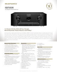
<strong>Model</strong> <strong>PM</strong>-<strong>11S3</strong> Owner’s <strong>Manual</strong><br />
<strong>Integrated</strong> <strong>Amplifier</strong>
ENGLISH FRANÇAIS ESPAÑOL<br />
n SAFETY PRECAUTIONS<br />
CAUTION<br />
RISK OF ELECTRIC SHOCK<br />
DO NOT OPEN<br />
CAUTION:<br />
TO REDUCE THE RISK OF ELECTRIC SHOCK, DO NOT<br />
REMOVE COVER (OR BACK). NO <strong>US</strong>ER-SERVICEABLE<br />
PARTS INSIDE. REFER SERVICING TO QUALIFIED<br />
SERVICE PERSONNEL.<br />
The lightning flash with arrowhead symbol, within an<br />
equilateral triangle, is intended to alert the user to the<br />
presence of uninsulated “dangerous voltage” within the<br />
product’s enclosure that may be of sufficient magnitude<br />
to constitute a risk of electric shock to persons.<br />
The exclamation point within an equilateral triangle is<br />
intended to alert the user to the presence of important<br />
operating and maintenance (servicing) instructions in the<br />
literature accompanying the appliance.<br />
WARNING:<br />
TO REDUCE THE RISK OF FIRE OR ELECTRIC SHOCK,<br />
DO NOT EXPOSE THIS APPLIANCE TO RAIN OR<br />
MOISTURE.<br />
Hot<br />
surface<br />
mark<br />
CAUTION:<br />
HOT SURFACE. DO NOT TOUCH.<br />
The top surface over the internal heat sink may become hot<br />
when operating this product continuously.<br />
Do not touch hot areas, especially around the “Hot surface<br />
mark” and the top panel.<br />
PRECAUTION:<br />
SURFACE CHAUDE. NE PAS TOUCHER.<br />
La surface supérieure du dissipateur de chaleur peut devenir<br />
chaude si vous utilisez ce produit en continu.<br />
Ne touchez pas les zones chaudes, tout particulièrement vers<br />
l’inscription “Hot surface mark” et le panneau supérieur.<br />
PRECAUCIÓN:<br />
SUPERFICIE CALIENTE. NO TOCAR.<br />
La superficie superior sobre el disipador de calor interno<br />
podría llegar a calentarse al operar este producto de forma<br />
continua.<br />
No toque las áreas calientes, especialmente las situadas<br />
alrededor de la “Hot surface mark” y del panel superior.<br />
IMPOTANT SAFETY<br />
INSTRUCTIONS<br />
1. Read these instructions.<br />
2. Keep these instructions.<br />
3. Heed all warnings.<br />
4. Follow all instructions.<br />
5. Do not use this apparatus near water.<br />
6. Clean only with dry cloth.<br />
7. Do not block any ventilation openings.<br />
Install in accordance with the manufacturer’s instructions.<br />
8. Do not install near any heat sources such as radiators, heat registers,<br />
stoves, or other apparatus (including amplifiers) that produce heat.<br />
9. Do not defeat the safety purpose of the polarized or grounding-type plug. A<br />
polarized plug has two blades with one wider than the other. A grounding<br />
type plug has two blades and a third grounding prong. The wide blade or<br />
the third prong are provided for your safety. If the provided plug does not<br />
fi t into your outlet, consult an electrician for replacement of the obsolete<br />
outlet.<br />
10. Protect the power cord from being walked on or pinched particularly at<br />
plugs, convenience receptacles, and the point where they exit from the<br />
apparatus.<br />
11. Only use attachments/accessories specified by the manufacturer.<br />
12. Use only with the cart, stand, tripod, bracket, or table<br />
specified by the manufacturer, or sold with the apparatus.<br />
When a cart is used, use caution when moving the cart/<br />
apparatus combination to avoid injury from tip-over.<br />
13. Unplug this apparatus during lightning storms or when<br />
unused for long periods of time.<br />
14. Refer all servicing to qualified service personnel.<br />
Servicing is required when the apparatus has been damaged in any way,<br />
such as power-supply cord or plug is damaged, liquid has been spilled or<br />
objects have fallen into the apparatus, the apparatus has been exposed to<br />
rain or moisture, does not operate normally, or has been dropped.<br />
15. Batteries shall not be exposed to excessive heat such as sunshine, fire or<br />
the like.<br />
CAUTION:<br />
To completely disconnect this product from the mains, disconnect the plug<br />
from the wall socket outlet.<br />
The mains plug is used to completely interrupt the power supply to the unit<br />
and must be within easy access by the user.<br />
PRECAUTION:<br />
Pour déconnecter complètement ce produit du courant secteur, débranchez<br />
la prise de la prise murale.<br />
La prise secteur est utilisée pour couper complètement l’alimentation de<br />
l’appareil et l’utilisateur doit pouvoir y accéder facilement.<br />
PRECAUCIÓN:<br />
Para desconectar completamente este producto de la alimentación eléctrica,<br />
desconecte el enchufe del enchufe de la pared.<br />
El enchufe de la alimentación eléctrica se utiliza para interrumpir por completo<br />
el suministro de alimentación eléctrica a la unidad y debe de encontrarse en<br />
un lugar al que el usuario tenga fácil acceso.<br />
FCC INFORMATION (For <strong>US</strong> customers)<br />
1. PRODUCT<br />
This product complies with Part 15 of the FCC Rules. Operation is subject<br />
to the following two conditions: (1) this product may not cause harmful<br />
interference, and (2) this product must accept any interference received,<br />
including interference that may cause undesired operation.<br />
2. IMPORTANT NOTICE: DO NOT MODIFY THIS PRODUCT<br />
This product, when installed as indicated in the instructions contained<br />
in this manual, meets FCC requirements. Modification not expressly<br />
approved by <strong>Marantz</strong> may void your authority, granted by the FCC, to use<br />
the product.<br />
3. NOTE<br />
This product has been tested and found to comply with the limits for<br />
a Class B digital device, pursuant to Part 15 of the FCC Rules. These<br />
limits are designed to provide reasonable protection against harmful<br />
interference in a residential installation.<br />
This product generates, uses and can radiate radio frequency energy and,<br />
if not installed and used in accordance with the instructions, may cause<br />
harmful interference to radio communications. However, there is no<br />
guarantee that interference will not occur in a particular installation. If this<br />
product does cause harmful interference to radio or television reception,<br />
which can be determined by turning the product OFF and ON, the user<br />
is encouraged to try to correct the interference by one or more of the<br />
following measures:<br />
• Reorient or relocate the receiving antenna.<br />
• Increase the separation between the equipment and receiver.<br />
• Connect the product into an outlet on a circuit different from that to<br />
which the receiver is connected.<br />
• Consult the local retailer authorized to distribute this type of product or<br />
an experienced radio/TV technician for help.<br />
For Canadian customers:<br />
This Class B digital apparatus complies with Canadian ICES-003.<br />
Cet appareil numérique de la classe B est conforme à la norme NMB-003 du<br />
Canada.<br />
I
n NOTES ON <strong>US</strong>E / OBSERVATIONS RELATIVES A L’UTILISATION / NOTAS SOBRE EL <strong>US</strong>O<br />
II<br />
WARNINGS AVERTISSEMENTS ADVERTENCIAS<br />
• Avoid high temperatures.<br />
Allow for sufficient heat dispersion when installed in<br />
a rack.<br />
• Handle the power cord carefully.<br />
Hold the plug when unplugging the cord.<br />
• Keep the unit free from moisture, water, and dust.<br />
• Unplug the power cord when not using the unit for<br />
long periods of time.<br />
• Do not obstruct the ventilation holes.<br />
• Do not let foreign objects into the unit.<br />
• Do not let insecticides, benzene, and thinner come<br />
in contact with the unit.<br />
• Never disassemble or modify the unit in any way.<br />
• Ventilation should not be impeded by covering<br />
the ventilation openings with items, such as<br />
newspapers, tablecloths or curtains.<br />
• Naked flame sources such as lighted candles<br />
should not be placed on the unit.<br />
• Observe and follow local regulations regarding<br />
battery disposal.<br />
• Do not expose the unit to dripping or splashing<br />
fluids.<br />
• Do not place objects filled with liquids, such as<br />
vases, on the unit.<br />
• Do not handle the mains cord with wet hands.<br />
• When the switch is in the OFF position, the<br />
equipment is not completely switched off from<br />
MAINS.<br />
• The equipment shall be installed near the<br />
power supply so that the power supply is easily<br />
accessible.<br />
• Do not keep the battery in a place exposed to<br />
direct sunlight or in places with extremely high<br />
temperatures, such as near a heater.<br />
• Eviter des températures élevées.<br />
Tenir compte d’une dispersion de chaleur<br />
suffisante lors de l’installation sur une étagère.<br />
• Manipuler le cordon d’alimentation avec<br />
précaution.<br />
Tenir la prise lors du débranchement du cordon.<br />
• Protéger l’appareil contre l’humidité, l’eau et la<br />
poussière.<br />
• Débrancher le cordon d’alimentation lorsque<br />
l’appareil n’est pas utilisé pendant de longues<br />
périodes.<br />
• Ne pas obstruer les trous d’aération.<br />
• Ne pas laisser des objets étrangers dans l’appareil.<br />
• Ne pas mettre en contact des insecticides, du<br />
benzène et un diluant avec l’appareil.<br />
• Ne jamais démonter ou modifier l’appareil d’une<br />
manière ou d’une autre.<br />
• Ne pas recouvrir les orifi ces de ventilation avec<br />
des objets tels que des journaux, nappes ou<br />
rideaux. Cela entraverait la ventilation.<br />
• Ne jamais placer de flamme nue sur l'appareil,<br />
notamment des bougies allumées.<br />
• Veillez à respecter les lois en vigueur lorsque vous<br />
jetez les piles usagées.<br />
• L’appareil ne doit pas être exposé à l’eau ou à<br />
l’humidité.<br />
• Ne pas poser d’objet contenant du liquide, par<br />
exemple un vase, sur l’appareil.<br />
• Ne pas manipuler le cordon d’alimentation avec les<br />
mains mouillées.<br />
• Lorsque l’interrupteur est sur la position OFF,<br />
l’appareil n’est pas complètement déconnecté du<br />
SECTEUR (MAINS).<br />
• L’appareil sera installé près de la source<br />
d’alimentation, de sorte que cette dernière soit<br />
facilement accessible.<br />
• Ne placez pas la pile dans un endroit exposé à<br />
la lumière directe du soleil ou dans des endroits<br />
présentant des températures extrêmement<br />
élevées, par exemple près d’un radiateur.<br />
• Evite altas temperaturas.<br />
• Permite la suficiente dispersión del calor cuando<br />
está instalado en la consola.<br />
• Maneje el cordón de energía con cuidado.<br />
• Sostenga el enchufe cuando desconecte el cordón<br />
de energía.<br />
• Mantenga el equipo libre de humedad, agua y<br />
polvo.<br />
• Desconecte el cordón de energía cuando no utilice<br />
el equipo por mucho tiempo.<br />
• No obstruya los orificios de ventilación.<br />
• No deje objetos extraños dentro del equipo.<br />
• No permita el contacto de insecticidas, gasolina y<br />
diluyentes con el equipo.<br />
• Nunca desarme o modifique el equipo de ninguna<br />
manera.<br />
• La ventilación no debe quedar obstruida por<br />
haberse cubierto las aperturas con objetos como<br />
periódicos, manteles o cortinas.<br />
• No deberán colocarse sobre el aparato fuentes<br />
inflamables sin protección, como velas encendidas.<br />
• A la hora de deshacerse de las pilas, respete la<br />
normativa para el cuidado del medio ambiente.<br />
• No exponer el aparato al goteo o salpicaduras<br />
cuando se utilice.<br />
• No colocar sobre el aparato objetos llenos de<br />
líquido, como jarros.<br />
• No maneje el cable de alimentación con las manos<br />
mojadas.<br />
• Cuando el interruptor está en la posición OFF, el<br />
equipo no está completamente desconectado de la<br />
alimentación MAINS.<br />
• El equipo se instalará cerca de la fuente de<br />
alimentación de manera que resulte fácil acceder<br />
a ella.<br />
• No coloque las pilas en un lugar expuesto a<br />
la luz directa del sol o donde la temperatura<br />
sea extremadamente alta, como cerca de una<br />
calefacción.<br />
ESPAÑOL<br />
FRANÇAIS<br />
n Cautions on installation<br />
Précautions d’installation<br />
Emplazamiento de la instalación<br />
z<br />
z z<br />
z<br />
Wall<br />
Paroi<br />
Pared<br />
ENGLISH<br />
z For proper heat dispersal, do not install this unit in a confined space,<br />
such as a bookcase or similar enclosure.<br />
• More than 12 in. (0.3 m) is recommended.<br />
• Do not place any other equipment on this unit.<br />
z Pour permettre la dissipation de chaleur requise, n’installez pas cette<br />
unité dans un espace confiné tel qu’une bibliothèque ou un endroit<br />
similaire.<br />
• Une distance de plus de 12 po (0,3 m) est recommandée.<br />
• Ne placez aucun matériel sur cet appareil.<br />
z Para la dispersión del calor adecuadamente, no instale este equipo en un<br />
lugar confinado tal como una librería o unidad similar.<br />
• Se recomienda dejar más de 12 pulg. (0,3 m) alrededor.<br />
• No coloque ningún otro equipo sobre la unidad.
Getting started<br />
Thank you for purchasing this marantz product. To ensure proper operation, please read this owner’s manual carefully before<br />
using the product.<br />
After reading the manual, be sure to keep it for future reference.<br />
Contents<br />
Getting started ·······································································1<br />
Accessories ····················································································1<br />
About this manual ········································································1<br />
Cautions on handling ····································································2<br />
About the remote control ····························································2<br />
Inserting the batteries···································································2<br />
Operating range of the remote control unit ··································2<br />
Features ·························································································3<br />
Part names and functions·····························································4<br />
Front panel ····················································································4<br />
Rear panel ·····················································································4<br />
Remote control ·············································································5<br />
Basic connections··································································6<br />
Preparations ··················································································6<br />
Connecting cables ········································································6<br />
Connecting the audio equipment ················································6<br />
Connecting the speakers ······························································7<br />
Connecting the speakers cables ···················································7<br />
Speaker connections ····································································8<br />
Bi-wiring connection ·····································································8<br />
Connecting players ·······································································9<br />
Connecting recorders ·································································10<br />
Connecting the power cord························································10<br />
Basic operation ·····································································11<br />
Before use ····················································································11<br />
Turning the power on ·································································11<br />
Turning the power standby ·························································11<br />
Turning the power off ·································································11<br />
Starting playback ········································································11<br />
Adjusting the levels ····································································12<br />
Adjusting the tone ······································································12<br />
Muting the sound ·······································································13<br />
Using headphone set ··································································13<br />
Switching the illumination lamp setting ·································13<br />
Advanced connections······················································14<br />
F.C.B.S. connection ·····································································14<br />
Preparation for F.C.B.S. connection ············································14<br />
Stereo complete bi-amp connection ···········································16<br />
Connection for 5.1 Multi-channel Playback ·································17<br />
Connecting P.DIRECT IN connectors ·········································19<br />
Connecting pre out connectors ·················································19<br />
Connecting the remote control connectors······························20<br />
Advanced operations·························································20<br />
Setting Auto standby mode ·······················································20<br />
Explanation terms ·······························································21<br />
Troubleshooting···································································21<br />
Troubleshooting ··········································································21<br />
Specifications ········································································24<br />
Index ··························································································24<br />
ENGLISH<br />
Accessories<br />
Check that the following parts are supplied with the product.<br />
q Owner’s manual ........................................................... 1<br />
w Power cord ................................................................... 1<br />
e Remote control (RC001<strong>PM</strong>SA) .................................... 1<br />
r R03/AAA batteries ....................................................... 2<br />
t Warranty card (for <strong>US</strong>A) ............................................... 1<br />
y Warranty card (for CANADA) ....................................... 1<br />
w e<br />
About this manual<br />
n Operation buttons<br />
The operations described in this manual are based mainly<br />
on remote control operation.<br />
n Symbols<br />
v<br />
NOTE<br />
This symbol indicates a reference page on<br />
which related information is described.<br />
This symbol indicates a supplementary<br />
information and tips for operations.<br />
This symbol indicates points to remember<br />
operations or function limitations.<br />
n Illustrations<br />
Note that the illustrations in these instructions are for<br />
explanation purposes and may differ from the actual unit.<br />
1<br />
Getting started<br />
Basic connections Basic operation Advanced connections Advanced operation Explanation terms Troubleshooting Specifications Index
ENGLISH<br />
Cautions on handling<br />
• Before turning the power on<br />
Check once again that all connections are correct and that<br />
there are no problems with the connection cables.<br />
• Power is supplied to some of the circuitry even when the<br />
unit is set to the standby mode. When going on vacation or<br />
leaving home for long periods of time, be sure to unplug the<br />
power cord from the power outlet.<br />
• About condensation<br />
If there is a major difference in temperature between the<br />
inside of the unit and the surroundings, condensation (dew)<br />
may form on the operating parts inside the unit, causing the<br />
unit not to operate properly.<br />
If this happens, let the unit sit for an hour or two with the<br />
power turned off and wait until there is little difference in<br />
temperature before using the unit.<br />
• Cautions on using mobile phones<br />
Using a mobile phone near this unit may result in noise. If<br />
that occurs, move the mobile phone away from this unit<br />
when it is in use.<br />
• Moving the unit<br />
Turn off the power and unplug the power cord from the<br />
power outlet. Next, disconnect the connection cables to<br />
other system units before moving the unit.<br />
• About care<br />
• Wipe the cabinet and control panel clean with a soft cloth.<br />
• Follow the instructions when using a chemical cleaner.<br />
• Benzene, paint thinner or other organic solvents as well as<br />
insecticide may cause material changes and discoloration<br />
if brought into contact with the unit, and should therefore<br />
not be used.<br />
2<br />
About the remote control<br />
The supplied remote control can be used to control marantz<br />
<strong>Integrated</strong> <strong>Amplifier</strong> and marantz Super Audio CD player.<br />
• The remote control may not operate some products.<br />
Inserting the batteries<br />
q Remove the rear lid in the<br />
direction of the arrow and<br />
remove it.<br />
e Put the rear cover back on.<br />
w Load the two batteries<br />
properly as indicated by<br />
the marks in the battery<br />
compartment.<br />
NOTE<br />
• Insert the specified batteries in the remote control unit.<br />
• Replace the batteries with new ones if the set does not<br />
operate even when the remote control unit is operated close<br />
to the unit. (The supplied batteries are only for verifying<br />
operation. Replace them with new batteries at an early date.)<br />
• When inserting the batteries, be sure to do so in the proper<br />
direction, following the q and w marks in the battery<br />
compartment.<br />
• To prevent damage or leakage of battery fluid:<br />
• Do not use a new battery together with an old one.<br />
• Do not use two different types of batteries.<br />
• Do not attempt to charge dry batteries.<br />
• Do not short-circuit, disassemble, heat or dispose of<br />
batteries in flames.<br />
• Do not keep the battery in a place exposed to direct sunlight<br />
or in places with extremely high temperatures, such as near<br />
a heater.<br />
• If the battery fluid should leak, carefully wipe the fluid off the<br />
inside of the battery compartment and insert new batteries.<br />
• Remove the batteries from the remote control unit if it will<br />
not be in use for long periods.<br />
• Used batteries should be disposed of in accordance with the<br />
local regulations regarding battery disposal.<br />
• The remote control unit may function improperly if<br />
rechargeable batteries are used.<br />
Operating range of the remote control unit<br />
Point the remote control unit at the remote sensor when<br />
operating it.<br />
Approx. 26.2ft / 8 m<br />
30°<br />
30°<br />
NOTE<br />
• The set may function improperly or the remote control unit<br />
may not operate if the remote control sensor is exposed to<br />
direct sunlight, strong artificial light from an inverter type<br />
fluorescent lamp or infrared light.<br />
• When using 3D video devices that transmit radio<br />
communication signals (such as infrared signals etc)<br />
between the various units (such as the monitor, 3D glasses,<br />
3D transmitter unit etc), the remote control unit may not<br />
operate due to interference from those radio communication<br />
signals. If this occurs, adjust the direction and distance of the<br />
3D communication for each unit, and check that the remote<br />
control unit operation is not affected by these signals.
Features<br />
HDAM®SA3 Module<br />
This unit includes the HDAM®SA3 which had been<br />
developed for high-end models. The HDAM®SA3 is<br />
incorporated into many components, such as the current<br />
feedback phono equalizer, balance buffer, and input buffer.<br />
Constant Current Feedback Phono Equalizer<br />
This unit incorporates the constant current feedback phono<br />
equalizer which had been developed for high-end models.<br />
This equalizer, developed by marantz, has the advantages of<br />
both NF-type and CR-type phono equalizers, and it supports<br />
both MM and MC cartridges.<br />
Current Feedback Balance Buffer Amplifi er<br />
The Current Feedback Balance Buffer Amplifi er, which<br />
incorporates the HDAM®SA3 amp module, is provided<br />
with this unit, in order to faithfully convey signals from<br />
Super Audio CD players and D/A converters that have highquality<br />
balanced output.<br />
Dedicated Input Buffers for All Line Input Jacks<br />
Each CD, LINE 1, LINE 2, RECORDER 1, and RECORDER 2<br />
input jack has its own input buffer amplifi er that incorporates<br />
an HDAM®SA3. These amplifi ers' arrangement are circuit<br />
designed close to the respective jacks. Therefore, each<br />
input signals are faithfully conveyed without interference<br />
between them.<br />
Linear Control Volume<br />
The control knob had adopted the high-end model design<br />
concept. For better S/N ratio, the MAS6116 from Micro<br />
Analog Systems and the HDAM®SA3 have been combined,<br />
which enables smooth adjustment in the range of 0 to -100<br />
dB in units of ±0.5 dB.<br />
Tone Control Amplifi er<br />
The electronic tone control amplifi er is provided for<br />
adjustment of bass (low frequency) and treble (high<br />
frequency) sound in units of 2 dB in the range of -8 to +8<br />
dB.<br />
Dual-Amplifi er Structure<br />
Amplifi er of this unit has dual structure, voltage amplifi er<br />
and power buffer, adopting high-end model design concept.<br />
This dual structure enables the power buffer amplifi er to<br />
drive the speakers powerfully, preventing infl uence from<br />
the back electromagnetic force from the speakers. The<br />
voltage amplifi er drives the power buffer with superlow<br />
distortion.<br />
New-Designed Current Feedback Power Amplifi er<br />
To minimize noise of power amplifi er, circuit design with<br />
lower impedance is incorporated. This enables the user to<br />
obtain natural acoustics.<br />
ENGLISH<br />
F.C.B.S.<br />
A Floating Control Bus System (F.C.B.S.) enables the<br />
user to connect up to four <strong>PM</strong>-<strong>11S3</strong> units, making a<br />
diversity of applications possible with complete bi-amp<br />
and multichannel connections. Moreover, a ground loop<br />
is not formed among multiple <strong>PM</strong>-<strong>11S3</strong> units connected;<br />
therefore, sound quality is not adversely affected.<br />
BI-AMP Mode<br />
Complete bi-amp connection proposed by marantz enables<br />
a level of reproduction of the acoustic fi eld never before<br />
achieved. Synchronized operation of two <strong>PM</strong>-<strong>11S3</strong> units is<br />
made possible by F.C.B.S. (Floating Control Bus System)<br />
connection, with each <strong>PM</strong>-<strong>11S3</strong> in Bi-Amp mode working<br />
as a monaural integrated amplifi er.<br />
Power Amplifi er Direct In Mode<br />
In this mode, this unit works as a power amplifi er. This<br />
mode will be useful in home theater systems.<br />
Display<br />
This unit adopts an LCD (Liquid Crystal Display) to display<br />
the input source and volume level. Compared with other<br />
types of display panels, an LCD requires less drive power<br />
and generates less radiation noise, which minimizes any<br />
adverse effect on sound quality.<br />
3<br />
Getting started<br />
Basic connections Basic operation Advanced connections Advanced operation Explanation terms Troubleshooting Specifi cations Index
ENGLISH<br />
Part names and functions<br />
For buttons not explained here, see the page indicated in parentheses ( ).<br />
Front panel<br />
q INPUT SELECTOR knob ····················· (11)<br />
w Speaker output switch button<br />
(SPEAKERS A, SPEAKERS B) ············ (11)<br />
e TONE button ······································ (12)<br />
r Headphone jack (PHONES) ··············· (13)<br />
t Display<br />
y Standby status indicator<br />
Indicates the status of the unit’s as follows:<br />
• Power “ON” .......................................Off<br />
• Standby ..............................................Red<br />
• Power “OFF” ......................................Off<br />
u Power switch (X ON/OFF) ················ (11)<br />
i Remote control sensor ························ (2)<br />
o PRE OUT switch button ···················· (19)<br />
4<br />
INPUT<br />
SELECTOR<br />
Q6<br />
Q4 Q5<br />
Q4<br />
DISPLAY<br />
TONE<br />
SPEAKERS<br />
A<br />
SPEAKERS<br />
B<br />
PHONES<br />
INTEGRATED AMPLIFIER <strong>PM</strong>-<strong>11S3</strong><br />
STANDBY<br />
X ON/OFF<br />
q werty u ioQ0Q11 Q22<br />
ATT.<br />
PRE OUT<br />
P.DIRECT<br />
IN<br />
PHONO<br />
MC<br />
Q3<br />
Q0 Power amplifier direct mode switch<br />
button (P.DIRECT IN) ························· (19)<br />
Q1 Phono equalizer switch button<br />
(PHONO MC) ········································· (9)<br />
Q2 VOLUME knob ···································· (11)<br />
Q3 Attenuator button (ATT.) ·················· (13)<br />
Q4 Illumination lamp ······························· (13)<br />
Q5 Power indicator ·································· (11)<br />
Indicates the status of the unit’s as follows:<br />
• Power “ON” .....................................Blue<br />
• Standby ...............................................Off<br />
• Power “OFF” ......................................Off<br />
Q6 DISPLAY button ································· (13)<br />
VOLUME<br />
Rear panel<br />
q<br />
3<br />
2<br />
1<br />
Q1<br />
3<br />
2<br />
1<br />
Q0<br />
w e r<br />
q PHONO GND (ground) terminal ········· (9)<br />
NOTE<br />
This terminal is not a safety ground.<br />
w Input terminals (INPUT) ······················ (9)<br />
e Input/output terminals (Recordings)<br />
(RECORDER1, RECORDER2) ·············· (10)<br />
r PRE OUT terminals ···························· (19)<br />
t Speaker system terminals<br />
(SPEAKER SYSTEMS) ······················ (7, 8)<br />
o<br />
t y u i<br />
y <strong>Amplifier</strong> mode switch ······················ (16)<br />
u F.C.B.S. terminals ······························· (14)<br />
i AC inlet (AC IN) ·································· (10)<br />
o REMOTE CONTROL terminals ·········· (20)<br />
Q0 Power amplifier direct terminals<br />
(P. DIRECT IN) ····································· (19)<br />
Q1 Balanced input terminals ···················· (9)
Remote control<br />
n Buttons for amplifier<br />
u<br />
q<br />
u<br />
w<br />
e<br />
r<br />
t<br />
y<br />
u<br />
i<br />
o<br />
Q0<br />
u<br />
q MENU button ····································· (12)<br />
w Input selector buttons (INPUT) ········· (11)<br />
e <strong>Amplifier</strong> power button (X AMP) ····· (11)<br />
r Remote control mode switch button<br />
(MODE AMP) ······································ (12)<br />
t Cursor buttons (df0 1)··················· (12)<br />
y ENTER button ····································· (12)<br />
u Buttons for Super Audio CD player<br />
i TONE switch button ·························· (12)<br />
o VOLUME buttons (df) ······················ (11)<br />
Q0 Attenuator button (ATT) ··················· (13)<br />
• The supplied remote control can be used<br />
to control marantz <strong>Integrated</strong> <strong>Amplifier</strong> and<br />
marantz Super Audio CD player.<br />
• When using this remote control, also refer<br />
to the operating instructions of the other<br />
devices.<br />
NOTE<br />
The remote control may not operate some<br />
products.<br />
n Buttons for Super Audio CD player<br />
q<br />
w<br />
e<br />
r<br />
t<br />
y<br />
u<br />
i<br />
o<br />
Q0<br />
Q1<br />
Q2<br />
Q3<br />
Q4<br />
Q5<br />
Q6<br />
Q7<br />
Q8<br />
Q9<br />
Q9<br />
W0<br />
W1<br />
Q9<br />
W2<br />
W3<br />
W4<br />
ENGLISH<br />
Part names and functions<br />
q Super Audio CD player power button<br />
(X CD)<br />
w MENU button<br />
e Remote control mode switch button<br />
(MODE CD)<br />
r Cursor buttons (df0 1)<br />
t ENTER button<br />
y Information display switch button<br />
(INFO)<br />
u Input selection button (DISC/INPUT)<br />
i Pause button (3)<br />
o Skip buttons (8, 9)<br />
Q0 Playback button (1)<br />
Q1 Stop button (2)<br />
Q2 RANDOM button<br />
Q3 PROGRAM button<br />
Q4 Numeric buttons (0 – 9, +10)<br />
Q5 FILTER button<br />
Q6 NOISE SHAPER button<br />
Q7 PHONES button<br />
Q8 SOUND MODE button<br />
Q9 Buttons for amplifier<br />
W0 Disc tray OPEN/CLOSE button<br />
W1 REPEAT button<br />
W2 CLEAR button<br />
W3 DC FILTER button<br />
W4 DISPLAY button<br />
5<br />
Getting started<br />
Basic connections Basic operation Advanced connections Advanced operation Explanation terms Troubleshooting Specifications Index
ENGLISH<br />
Basic connections<br />
NOTE<br />
• Do not plug in the power cord until all connections have been<br />
completed.<br />
• When making connections, also refer to the operating<br />
instructions of the other components.<br />
• Be sure to connect the left and right channels properly (left<br />
with left, right with right).<br />
• Do not bundle power cords with connection cables. Doing so<br />
can result in humming or noise.<br />
• Do not turn up the volume without a turntable connected to<br />
the PHONO input terminals. Doing so will cause humming<br />
or noise.<br />
6<br />
Preparations<br />
Connecting cables<br />
Select the cables according to the equipment being connected.<br />
Audio cables<br />
Analog connections (UNBALANCED)<br />
L<br />
R<br />
Pin-plug cable (sold separately)<br />
Analog connections (BALANCED)<br />
Speaker connections<br />
Balance cables (sold separately)<br />
Speaker cables (sold separately)<br />
L<br />
R<br />
Connecting the audio equipment<br />
Cautions on playing SA sources:<br />
When regular speakers not compatible with SA sources<br />
(DVD Audio discs, Super Audio CDs and other sources,<br />
including treble components above the audible range),<br />
set the properties of the player (DVD Audio player, Super<br />
Audio CD player, etc.) for use with regular speakers (or<br />
amplifiers).The speakers may be damaged if the volume is<br />
set too high when playing SA sources. For instructions on<br />
player settings, refer to the operating instructions included<br />
with the player.
Connecting the speakers<br />
Connecting the speakers cables<br />
Carefully check the left (L) and right (R) channels and + (red)<br />
and – (white) polarities on the speakers being connected to<br />
the unit, and be sure to connect the channels and polarities<br />
correctly.<br />
1 Peel<br />
2 Turn<br />
3 Insert<br />
4 Turn<br />
off about 0.03 ft / 10 mm of<br />
sheathing from the tip of the speaker<br />
cable, then either twist the core wire<br />
tightly or apply solder to it.<br />
the speaker terminal<br />
counterclockwise to loosen it.<br />
the speaker cable’s core<br />
wire to all the way into the speaker<br />
terminal.<br />
the speaker terminal clockwise<br />
to tighten it.<br />
Spade lug connector<br />
When using a banana plug<br />
Tighten the speaker terminal firmly before inserting the banana<br />
plug.<br />
NOTE<br />
• Connect the speaker cables so they do not stick out of the<br />
speaker terminals. The protection circuit may be activated if<br />
the wires touch the rear panel or if the + and – sides touch<br />
each other (vpage 21 “Protection Circuit”).<br />
• Never touch the speaker terminals while the power supply is<br />
connected. Doing so could result in electric shock.<br />
ENGLISH<br />
Speaker impedance<br />
Use speakers with impedances within the ranges shown<br />
below to suit how they are used.<br />
Speakers used Impedance<br />
A 4 – 16 Ω<br />
B 4 – 16 Ω<br />
A and B 8 – 16 Ω<br />
Bi-wiring Connection 8 – 16 Ω<br />
Protection circuit<br />
The protection circuit is be activated in the following situations:<br />
• If the speaker cable wire touches the rear panel or screws<br />
or if the speaker cable wire touches the speaker cable’s +<br />
and – sides are touching<br />
• If the surrounding temperature is extremely high<br />
• If the inside of the amplifier gets hot to extended use at a<br />
high output<br />
If this happens, unplug the power cord, then check the<br />
connections of the speaker cables and input cables.<br />
If the unit becomes very hot, wait for it to cool off and improve<br />
the ventilation around it. After doing this, plug the power cord<br />
back in.<br />
If the protection circuit is activated even though there are no<br />
problems with the ventilation around the unit or in connections,<br />
the unit may be damaged. Turn off the power and then contact<br />
a marantz service center.<br />
7<br />
Getting started Basic connections Basic operation Advanced connections Advanced operation Explanation terms Troubleshooting Specifications Index
ENGLISH<br />
Speaker connections<br />
• The same signal is output from the SPEAKER A and B terminals.<br />
• When only one set of speakers is to be connected, use either the SPEAKER A or B terminals.<br />
8<br />
Speakers A Speakers B<br />
(L) (R)<br />
(L)<br />
(R)<br />
w q w q<br />
w q w q<br />
3<br />
2<br />
1<br />
3<br />
2<br />
1<br />
Bi-wiring connection<br />
Connecting the speakers<br />
• When bi-wiring with bi-wireable speakers, connect the mid and high range terminals to<br />
SYSTEM (A) (or SYSTEM (B)), the low range terminals to SYSTEM (B) (or SYSTEM (A)).<br />
• This enables playback with minimal interference between the high-range speaker unit and the<br />
low-range speaker unit.<br />
Remove<br />
shorting bar<br />
Speaker (R)<br />
Speaker (L)<br />
Remove<br />
shorting bar
ENGLISH<br />
Connecting recorders<br />
Recorder-2 Recorder-1<br />
L<br />
R<br />
L<br />
R<br />
10<br />
AUDIO<br />
AUDIO IN<br />
AUDIO OUT<br />
L<br />
R<br />
L<br />
R<br />
L<br />
R<br />
L<br />
R<br />
3<br />
2<br />
1<br />
3<br />
2<br />
1<br />
L<br />
R<br />
L<br />
R<br />
L<br />
R<br />
L<br />
R<br />
AUDIO<br />
AUDIO IN<br />
L<br />
R<br />
AUDIO OUT<br />
L<br />
R<br />
Connecting the power cord<br />
Do not plug in the power cord until all connections have been completed.<br />
AC IN<br />
Power cord (supplied)<br />
To household power outlet<br />
(AC 120 V, 60 Hz)<br />
NOTE<br />
Insert the plugs securely. Loose connections will result in the generation of noise.
Basic operation<br />
Before use<br />
Turning the power on<br />
Press X ON/OFF on the unit.<br />
• Power is turned on.<br />
• The power indicator lights in blue.<br />
• The unit will be ready to start playback after several seconds.<br />
Turning the power standby<br />
Press X AMP.<br />
• The power is set to the standby mode.<br />
• The Standby status indicator lights in<br />
red.<br />
• Press X AMP to turn on power from standby mode.<br />
• You can also turn on power by using either INPUT SELECTOR<br />
on this unit from standby mode.<br />
NOTE<br />
Power continues to be supplied to some of the circuitry even<br />
when the power is in the standby mode. When leaving home<br />
for long periods of time or when going on vacation, either<br />
press X ON/OFF to turn off the power, or unplug the power<br />
cord from the power outlet.<br />
Turning the power off<br />
Press X ON/OFF on the unit.<br />
• Power is turned off.<br />
• All indicators will turn off.<br />
Starting playback<br />
1<br />
Press<br />
2<br />
Use<br />
ENGLISH<br />
SPEAKERS A/SPEAKERS B on the unit to<br />
select the speaker system to be used for playback.<br />
INPUT SELECTOR on the<br />
unit or INPUT df on the remote<br />
control to select the source.<br />
• The input source changes as follows<br />
with each press of the button:<br />
3<br />
Start<br />
4 Adjust<br />
CD<br />
BALANCED<br />
PHONO<br />
LINE-1<br />
LINE-2<br />
RECORDER1<br />
RECORDER2<br />
playing back the source.<br />
the VOLUME df on the unit or remote<br />
control to the desired level.<br />
11<br />
Getting started Basic connections Basic operation Advanced connections Advanced operation Explanation terms Troubleshooting Specifications Index
ENGLISH<br />
Adjusting the levels<br />
n Left and right channel balance<br />
The volume level of the left and right channels can be trimmed<br />
in 0.5 dB steps across a 0.0 – 9.0 dB range. When the unit is<br />
shipped from the factory, the volume level is set to 0.0 dB<br />
(maximum).<br />
1 Press<br />
12<br />
MENU.<br />
The unit enters the level adjustment<br />
mode.<br />
• The left channel level value flashes.<br />
2 Press<br />
3 Press<br />
df to adjust the left channel level.<br />
1.<br />
The adjustment mode selects the right channel.<br />
• The tight channel level value flashes.<br />
4 Press<br />
5<br />
Press<br />
df to adjust the right channel level.<br />
MENU.<br />
The unit exits the adjustment mode.<br />
• If you have connected a “SLAVE” device using the F.C.B.S.<br />
connection (vpage 14), proceed to the slave setting.<br />
Adjusting the tone<br />
n Low frequency range<br />
The low frequency range can be trimmed in 2 dB steps across<br />
a –8 – +8 dB range. When the unit is shipped from the factory,<br />
the level is set to 0.0 dB. Before making this adjustment, press<br />
TONE on the unit or the remote control to set the tone control<br />
to on.<br />
1 Press<br />
2 Press<br />
3 Press<br />
MENU.<br />
The unit enters the level adjustment<br />
mode.<br />
ENTER.<br />
The adjustment mode selects the<br />
low frequency range.<br />
df to adjust the level.<br />
• If not operated for 15 seconds, the current setting is saved<br />
and the display returns to normal.<br />
n High frequency range<br />
The high frequency range can be trimmed in 2 dB steps across<br />
a –8 – +8 dB range. When the unit is shipped from the factory,<br />
the level is set to 0.0 dB. Before making this adjustment, press<br />
TONE on the unit or the remote control to set the tone control<br />
to on.<br />
1 Press<br />
2 Press<br />
3 Press<br />
MENU.<br />
The unit enters the level adjustment<br />
mode.<br />
ENTER twice.<br />
The adjustment mode selects the<br />
high frequency range.<br />
df to adjust the level.<br />
Starting playback<br />
• If not operated for 15 seconds, the current setting is saved<br />
and the display returns to normal.<br />
NOTE<br />
Before making the adjustment for level and tone, press MODE/<br />
AMP to set its control mode to amplifier.
ENGLISH<br />
Advanced connections<br />
F.C.B.S. connection<br />
The marantz F.C.B.S. (Floating Control Bus System) is the high quality sound system for link<br />
control between multiple <strong>PM</strong>-<strong>11S3</strong> units (up to 4 units). Each unit is controlled via its ID number<br />
registered beforehand.<br />
The ID numbers need to be set to an operating unit (master) and a subordinate unit (slave)<br />
receiving the command from the master. For slave units, register ID numbers in the order of<br />
command reception from the master.<br />
Once registered the ID numbers, the units will enable link control operations such as input<br />
selection, volume control, on/off selection of muting, display, tone control, etc.<br />
Furthermore, F.C.B.S. connection of multiple units has the feature that switches this unit's<br />
output from stereo to monaural so that the unit can works as a monaural output amplifier.<br />
Follow the respective instructions to make the necessary settings.<br />
Preparation for F.C.B.S. connection<br />
n Making the F.C.B.S. connection<br />
To use multiple <strong>PM</strong>-<strong>11S3</strong> units, make this connection in addition to audio connection.<br />
For details on each connection feature, refer to the respective instructions.<br />
Prepare the correct number of portable audio connection cables for the number of units to be<br />
connected. Either of the following types of connection cables are adequate.<br />
• Monaural mini plug "! monaural mini plug connecting cable<br />
• Stereo mini plug "! stereo mini plug connecting cable<br />
NOTE<br />
Do not use connecting cables that contain resistance.<br />
14<br />
n Connection example<br />
In the connection of the following example, an unit with ID number 1 acts as a master amplifier<br />
to control all the other slave units with ID numbers 2 to 4.<br />
<strong>PM</strong>-<strong>11S3</strong><br />
ID 1 Master<br />
<strong>PM</strong>-<strong>11S3</strong><br />
<strong>PM</strong>-<strong>11S3</strong><br />
<strong>PM</strong>-<strong>11S3</strong><br />
ID 2 Slave<br />
ID 3 Slave<br />
ID 4 Slave<br />
NOTE<br />
• The <strong>PM</strong>-<strong>11S3</strong> F.C.B.S. function is only valid between the same <strong>PM</strong>-<strong>11S3</strong> models. This<br />
function may not operate correctly if other marantz models (<strong>PM</strong>-11S2, etc.) are connected.<br />
• To turn the power of multiple F.C.B.S.-connected units ON/OFF, switch the power ON in<br />
order of lowest to highest ID number, and switch the power OFF in order of highest to lowest<br />
ID number.
n How to set ID number for F.C.B.S.<br />
When the unit is turned on, the display shows the ID number for three seconds.<br />
For a master unit, ID number 1 needs to be assigned.<br />
For a slave unit, set any of ID numbers 2 to 4.<br />
INPUT SELECTOR<br />
INPUT<br />
SELECTOR<br />
DISPLAY<br />
TONE<br />
SPEAKERS<br />
A<br />
SPEAKERS<br />
B<br />
DISPLAY<br />
PHONES<br />
INTEGRARED AMPLIFIER <strong>PM</strong>-<strong>11S3</strong><br />
STANDBY<br />
X ON/OFF<br />
X ON/OFF<br />
ATT.<br />
PRE OUT<br />
P.DIRECT<br />
IN<br />
PHONO<br />
MC<br />
VOLUME<br />
1 While<br />
2 Turn<br />
3<br />
Turn<br />
4<br />
Again<br />
holding DISPLAY on the unit, press X ON/OFF.<br />
INPUT SELECTOR on the unit to select an ID number.<br />
the unit off.<br />
turn the unit on.<br />
• The setting is saved.<br />
• The unit registered as a slave shows “SLAVE” on the display.<br />
ENGLISH<br />
F.C.B.S. connection<br />
NOTE<br />
• If using this unit by itself as a stereo amplifier, set the ID number to “0” (Default setting is<br />
“0”).<br />
• If the ID number is set to a number other than “0”, this unit cannot be used for standalone<br />
operation.<br />
15<br />
Getting started Basic connections Basic operation Advanced connections Advanced operation Explanation terms Troubleshooting Specifications Index
ENGLISH<br />
Stereo complete bi-amp connection<br />
This mode enables the two amplifiers connected to this unit<br />
to function as one monaural amplifier. To use this mode, two<br />
F.C.B.S. connected <strong>PM</strong>-<strong>11S3</strong> units are required.<br />
To switch the mode, use the amplifier mode switch on the<br />
rear panel while the power is off.<br />
The figures below show example displays in the stereo and<br />
bi-amp modes.<br />
16<br />
Stereo mode<br />
Bi-amp mode<br />
Bi-amp mode indicator<br />
In bi-amp mode, connect to the left channel input jack. The<br />
right channel input is disabled.<br />
The same signals are output from the left and right output<br />
jacks.<br />
NOTE<br />
• Always turn the power to the unit OFF before changing the<br />
operating mode switch setting. Turning the power ON again<br />
activates the new setting.<br />
• When in bi-amp mode, the R channel input jacks cannot be<br />
used.<br />
• When in bi-amp mode, the signals input into the L channel<br />
are output from both channels. Therefore, the same signals<br />
are output from the L channel and R channel in RECORDER<br />
OUT, PRE OUT, PHONES OUT.<br />
• Speaker systems connected using complete bi-amp<br />
connections must support bi-amp connections. Before<br />
connecting your speakers, check in the instruction manual<br />
that came with the speakers or contact the manufacturer to<br />
confirm whether they support bi-amp connection.<br />
Set <strong>PM</strong>-<strong>11S3</strong><br />
for L CH<br />
to ID 1.<br />
OPEN/<br />
CLOSE<br />
3<br />
2<br />
1<br />
DISPLAY<br />
OFF<br />
PHONES<br />
OFF<br />
MULT1<br />
ON/OFF<br />
iPod/<strong>US</strong>B DISC/INPUT<br />
PHONES<br />
3<br />
2<br />
1<br />
Remove<br />
shorting bar.<br />
SUPER AUDIO CD PLATER SA-<strong>11S3</strong><br />
<br />
<br />
LEVEL<br />
PLAY<br />
STOP<br />
PA<strong>US</strong>E<br />
• Set SPEAKER A button on front panel in<br />
ON position.<br />
• Set to “BI-AMP”.<br />
L CH<br />
speaker<br />
Remove<br />
shorting bar.<br />
To power<br />
outlet.<br />
Set <strong>PM</strong>-<strong>11S3</strong><br />
for R CH<br />
to ID 2.<br />
3<br />
2<br />
1<br />
3<br />
2<br />
1<br />
Remove<br />
shorting bar.<br />
<br />
<br />
F.C.B.S. connection<br />
• Set SPEAKER A button on front panel in<br />
ON position.<br />
• Set to “BI-AMP”.<br />
R CH<br />
speaker<br />
Remove<br />
shorting bar.<br />
To power<br />
outlet.
Connection for 5.1 Multi-channel Playback<br />
The three units are connected using F.C.B.S. For the F.C.B.S connection, prepare 3 audio connection cables, and refer to F.C.B.S. ( vpage 14).<br />
Connect the outputs of players that have 5.1 channel analog outputs to each of the three units.<br />
If using an active subwoofer, see the instruction manual that came with the subwoofer for further instructions.<br />
Set the ID numbers for the three amplifiers as explained in How to set ID number for F.C.B.S. (vpage 15).<br />
• When the ID 1 unit is operated, ID 2 and ID 3 units will operate in sync.<br />
• Set SPEAKER A button on front panel in<br />
ON position.<br />
• Set to “STEREO”.<br />
For front L/R speakers<br />
Set <strong>PM</strong>-<strong>11S3</strong> to ID 1.<br />
3<br />
2<br />
1<br />
3<br />
2<br />
1<br />
L CH front<br />
speaker<br />
R CH front<br />
speaker<br />
To power<br />
outlet.<br />
SACD multi-channel player, etc.<br />
3<br />
2<br />
1<br />
3<br />
2<br />
1<br />
Active<br />
subwoofer<br />
MULTI CHANNEL AUDIO OUT<br />
FRONT R FRONT L SURROUND R SURROUND L SUB-WOOFER CENTER<br />
• Set SPEAKER A button on front panel in ON position.<br />
• Set PRE OUT button on front panel in ON position.<br />
• Set to “STEREO”.<br />
For center speaker or subwoofer<br />
Set <strong>PM</strong>-<strong>11S3</strong> to ID 2.<br />
To line input<br />
jack<br />
Front center<br />
speaker<br />
To power<br />
outlet.<br />
For surround speakers<br />
Set <strong>PM</strong>-<strong>11S3</strong> to ID 3.<br />
3<br />
2<br />
1<br />
• Set SPEAKER A button on front panel in<br />
ON position.<br />
• Set to “STEREO”.<br />
3<br />
2<br />
1<br />
L CH surround<br />
speaker<br />
R CH surround<br />
speaker<br />
ENGLISH<br />
F.C.B.S. connection<br />
To power<br />
outlet.<br />
17<br />
Getting started Basic connections Basic operation Advanced connections Advanced operation Explanation terms Troubleshooting Specifications Index
ENGLISH<br />
n Speaker Positioning for Super Audio Multichannel<br />
Sound<br />
In order to enjoy Super Audio CD multi-channel sound with<br />
the best possible acoustics, it is recommended to position<br />
speakers as specified in ITU-R BS.775-1 of the International<br />
Telecommunication Union (ITU). Super Audio CD multichannel<br />
discs are recorded and mixed so as to achieve the<br />
optimum effect with a speaker system laid out as specified<br />
in ITU-R BS.775-1.<br />
• With Super Audio CD multi-channel discs, the music<br />
signals are basically recorded using 5 channels (3 - 6<br />
channels sometimes), but in some cases, LFE (for<br />
subwoofer) is recorded as a sixth channel.<br />
• Each disc indicates how many channels have been<br />
recorded on it.<br />
• The basic layout is 3 speakers in the front and 2 in the<br />
back since multi-channel discs usually have 5 channels.<br />
The 2 front, 1 center and 2 surround (rear) speakers<br />
should be set in a circle around the listening point. If using<br />
speakers of differing sizes, adjust volume balance from<br />
the amplifier.<br />
• The location of the subwoofer in the figure is just for<br />
explanatory purposes. It can be located anywhere in the<br />
room. For connection and positioning instructions, see the<br />
instruction manual that came with the subwoofer.<br />
18<br />
Front speaker<br />
(Left)<br />
Rear speaker<br />
(Left Surround)<br />
Subwoofer<br />
Center<br />
speaker<br />
60°<br />
approx.110° approx.110°<br />
Recommended<br />
listening position<br />
F.C.B.S. connection<br />
Front speaker<br />
(Right)<br />
Rear speaker<br />
(Right Surround)<br />
• ITU (International Telecommunication Union)<br />
The ITU is a special organization of the United Nations. It<br />
consists of a number of organs, one of which is the Radio<br />
Broadcasting Section.<br />
ITU-R BS in the recommendation which consists of standards<br />
relating to broadcasting (audio) operations, one of which is the<br />
ITU-R BS.775-1 which governs “multi-channel stereo sound<br />
systems”.
Connecting P.DIRECT IN connectors<br />
If you use a preamplifier, connect it as shown below, and then you can use this unit as a power<br />
amplifier.<br />
Press and hold P.DIRECT IN on the unit for 2 seconds or longer.<br />
• The power direct mode setting changes with each press of the button.<br />
On<br />
Off<br />
(Factory default)<br />
• If the mode is set to on, the display shows “POWER AMP DIRECT”.<br />
On: Allows the device connected to the Power Amp Direct connector to be played.<br />
Off: Allows the program source selected using INPUT SELECTOR to be played.<br />
R<br />
L<br />
Pre-amplifier Speakers<br />
(L) (R)<br />
R<br />
3<br />
2<br />
1<br />
L<br />
3<br />
2<br />
1<br />
To PRE OUT<br />
connectors<br />
NOTE<br />
• When the POWER AMP DIRECT is “ON”, adjustment of the volume, balance and tone on the<br />
main unit has no effect. Adjust the volume on the pre-amplifier.<br />
• When the POWER AMP DIRECT is “ON”, the main unit outputs at maximum volume. Check<br />
the output level on the input device before playing it and adjust the volume accordingly.<br />
ENGLISH<br />
Connecting pre out connectors<br />
If you use a power amplifier, connect it as shown below, and then you can use this unit as a<br />
preamplifier.<br />
• Press the PRE OUT switch button on this unit to turn on the PRE OUT function.<br />
• For connecting speaker systems, refer to the instruction manual supplied with the power<br />
amplifier to be used.<br />
3<br />
2<br />
1<br />
L<br />
R<br />
3<br />
2<br />
1<br />
Power-amplifier<br />
L<br />
R<br />
To input<br />
connectors<br />
NOTE<br />
The power amp direct function and the pre out function cannot work at the same time.<br />
19<br />
Getting started Basic connections Basic operation Advanced connections Advanced operation Explanation terms Troubleshooting Specifications Index
ENGLISH<br />
Connecting the remote control connectors<br />
When you use this unit connected to marantz audio components, it sends control signals to<br />
operate each component.<br />
n Connection<br />
Use the remote connection cable (supplied with a marantz audio component you want to<br />
connect) to connect the REMOTE CONTROL OUT terminal of this unit to the REMOTE<br />
CONTROL IN terminal of the component to be connected.<br />
n Setting<br />
Set the remote control switch located on the rear panel of the connected audio component to<br />
“EXTERNAL” or “EXT.” to use this feature.<br />
• This setting will disable remote sensor reception of the connected audio component.<br />
• To operate the connected audio component, point the remote control at the remote sensor<br />
of this unit.<br />
• To use the system control to this unit via the connected device, make the connection following<br />
the instructions supplied with the connected device.<br />
20<br />
Input Output<br />
IN OUT<br />
REMOTE CONTROL<br />
CD player<br />
RC OUT<br />
Option unit<br />
(such as remote control receiver unit)<br />
Advanced operations<br />
Setting Auto standby mode<br />
With the Auto standby mode ON, this unit will automatically enter the standby mode after<br />
about 30 continuous minutes of no output from the selected input source.<br />
Press and hold TONE on this unit for 5 seconds or longer.<br />
• Auto standby mode is switched between On and Off with each press of the button.<br />
On<br />
(Factory default)<br />
• If the mode is set to off, the display shows “AUTO STBY OFF”.<br />
• This unit will automatically enter standby mode after about continuous 30 minutes in the<br />
following conditions.<br />
• No operation performed on the remote control.<br />
• No operation of this unit.<br />
• The display will show the remaining time for three minutes before the units enters standby<br />
mode.<br />
• In F.C.B.S. connection, only the ID 1 master unit activates Auto standby mode. If the ID 1<br />
master unit is operated with no audio input, set the Auto standby mode to OFF.<br />
Off
Explanation terms<br />
MM/MC cartridge select<br />
There are two types--MM (Moving Magnet) and MC (Moving<br />
Coil)--of cartridges for turntable.<br />
As the output levels for these two types of cartridges differ,<br />
the setting of the phono equalizer that is mounted in this unit<br />
must be switched according to the type of cartridge for your<br />
turntable. For switching, use the PHONO MC button on this unit.<br />
Speaker impedance<br />
This is certain-rated resistance of the speaker set to an<br />
alternating current and expressed in ohms.<br />
The smaller the impedance, the greater the output. However,<br />
load on the amplifier is increased. Use speakers whose<br />
impedance is supported by this unit<br />
Bi-wiring Connection<br />
This method of connecting a speaker by using two speaker<br />
cables enables separate transmission of treble and bass<br />
signals.<br />
This enables playback with minimal interference between the<br />
high-range speaker unit and the low-range speaker unit.<br />
Protection Circuit<br />
This is a function to prevent damage to components within<br />
the power supply when an abnormality such as an overload or<br />
excess voltage occurs for any reason.<br />
In this unit, the power indicator blinks and the unit enters<br />
standby mode when an abnormality occurs.<br />
Troubleshooting<br />
Troubleshooting<br />
n About the protection circuit<br />
This unit is equipped with a protection circuit to protect the<br />
amplifier circuits and speaker system from damage.<br />
If the protection circuit is activated, the sound is instantly<br />
muted.<br />
In this case, the message “PROTECT” flashes on the display<br />
panel, and the STANDBY indicator also flashes.<br />
To deactivate the protection circuit, turn the unit off then back<br />
on again after about 1 minute or more.<br />
At power on<br />
For about 8 seconds after the power is turned on, the protection<br />
circuit is activated, muting the sound to give the amplifier<br />
circuits time to stabilize. Once the amplifier circuits stabilize,<br />
the protection circuit is released, and audio is enabled.<br />
In the event of overcurrent<br />
The protection circuit is activated if current exceeding a certain<br />
level is detected, which can happen if excessive signal flow is<br />
input to the amplifier or if the unit is connected to a speaker<br />
system of less than 4 Ω impedance. The protection circuit is<br />
also activated if a speaker cable shorts.<br />
In such cases, the message “PROTECT” flashes on the display,<br />
and the volume is automatically reduced. After approximately<br />
8 seconds, the protection circuit is released. Therefore, the<br />
volume needs readjusting to continue normal use.<br />
If the overcurrent continues, the amplifier shuts itself OFF,<br />
and the STANDBY indicator flashes.<br />
To deactivate the protection circuit, turn the unit off then back<br />
on again after about 1 minute or more.<br />
If excessive ultrabass signals are input<br />
The protection circuit is also activated if ultrabass signals are<br />
input. In such a case, the STANDBY indicator flashes, and<br />
the volume is automatically reduced. After approximately<br />
8 seconds, the protection circuit is released. Therefore, the<br />
volume needs readjusting to continue normal use. If excessive<br />
ultrabass signal input continues or if DC voltage is detected<br />
owing to trouble with the amplifier, the amplifier shuts itself<br />
OFF, and the STANDBY indicator flashes.<br />
To deactivate the protection circuit, turn the unit off then back<br />
on again after about 1 minute or more.<br />
ENGLISH<br />
If the main-amplifier overheats<br />
The protection circuit is activated if the temperature of the main<br />
amplifier section rises above a certain level, which can happen<br />
if the amplifier is continuously used with excessive signal flow<br />
being input to it. The protection circuit is also activated when<br />
the specified operating temperature is exceeded, which can<br />
happen if the vents on top of the amplifier are covered or if<br />
the amplifier is installed on a cramped audio rack. In such<br />
a case, the STANDBY indicator flashes, and the volume is<br />
automatically reduced. After approximately 8 seconds, the<br />
protection circuit is released. Therefore, the volume needs<br />
readjusting to continue normal use.<br />
If the temperature does not sufficiently fall within a certain<br />
amount of time after the protection circuit activation, the<br />
amplifier shuts itself OFF, and the STANDBY indicator flashes.<br />
To deactivate the protection circuit, turn the unit off, let it<br />
stand until it cools down, then turn it ON again.<br />
In the event of amplifier trouble<br />
The protection circuit is activated, and the power is<br />
automatically shut OFF, if an abnormality is detected in the<br />
power circuit. The same happens if the main fuse inside the<br />
amplifier blows. In such cases, the STANDBY indicator flashes.<br />
Turn the unit off then after several minutes turn it on again.<br />
If the display does not light up, and the STANDBY indicator<br />
remains flashing after the unit is turned on again, the unit may<br />
be in failure.<br />
21<br />
Getting started Basic connections Basic operation Advanced connections Advanced operation Explanation terms Troubleshooting Specifications Index
ENGLISH<br />
n Error messages<br />
When multiple amplifiers are connected by F.C.B.S., the error<br />
messages described in the table below may be displayed on<br />
the display. In such a case, ID number setting or remote cable<br />
connection may be in failure. Check the ID number or remote<br />
cable connection, referring to the table below. For details on<br />
ID number setting, see “How to set ID number for F.C.B.S.”<br />
(vpage 15).<br />
Indication Meaning<br />
1 ERROR 02 Multiple amplifiers take ID No. 2.<br />
2 ERROR 03 Multiple amplifiers take ID No. 3.<br />
3 ERROR 04 Multiple amplifiers take ID No. 4.<br />
! Assign different ID numbers to the amplifiers.<br />
4 ERROR 11 The amplifiers with ID Nos. 2-4 cannot<br />
communicate with the amplifier with ID<br />
No. 1.<br />
! If the amplifier with ID No. 1 is not on, turn it ON.<br />
! Check that the remote cable is properly connected.<br />
5 ERROR 12 The amplifier with ID No. 1 cannot<br />
communicate with the amplifiers with ID<br />
Nos. 2-4.<br />
! If multiple amplifiers take ID No. 1, set ID numbers<br />
properly.<br />
! If the amplifier with ID No. 1 is connected to the amplifier<br />
with ID No. 0, set ID numbers properly.<br />
! Check that the remote cable is properly connected.<br />
22<br />
Troubleshooting<br />
n Are the connections correct?<br />
n Is the unit being operated as described in the owner’s manual?<br />
n Are the other components operating properly?<br />
If this unit does not operate properly, check the items listed in the table below. If the problem persist there may be a malfunction.<br />
In that case, disconnect the power immediately and contact your retail outlet.<br />
Symptom Cause Countermeasure Page<br />
When the power is turned • The power cord’s plug is not fully • Check the cord is securely inserted into 10<br />
on, the power indicator does plugged in.<br />
the unit’s AC inlet and the wall power<br />
not light and no sound is<br />
produced.<br />
outlet.<br />
Power switches off suddenly • The protection circuit will be activated • Please switch off power at once, and 7<br />
while you are using the unit, depending upon the temperature rise in re-apply the power after the body<br />
the power indicator will the internal parts of the unit.<br />
temperature has fallen sufficiently.<br />
flash in red at intervals of<br />
• Please re-install the unit in a place 2<br />
approximately 2 seconds.<br />
having good ventilation.<br />
Power switches off suddenly • A speaker with impedance not • Please use speakers which have the 7<br />
while you are using the supported by this unit is used.<br />
specified impedance.<br />
unit, the power indicator • The protection circuit has been activated • Unplug the power cord, then after 7<br />
will flash red at intervals of because the core wires of different twisting the core wires together<br />
approximately 0.5 seconds. speaker cables have touched each other tightly again, or effecting termination<br />
or a core wire was slipped out of the treatments etc, please reconnect once<br />
terminal and is touching the unit’s rear<br />
panel.<br />
again.<br />
Even applying power, the • The amplifier circuit in failure. • Switch off the power and please contact –<br />
power display flashes red at<br />
intervals of approximately 0.5<br />
seconds.<br />
the marantz service adviser.<br />
The power indicator lights • The speaker cables are not fully • Connect securely.<br />
7<br />
but no sound is produced. connected.<br />
• The device you want to listen to has not • Insure the correct input is selected.<br />
been selected.<br />
11<br />
• The volume control is set to minimum. • Set to an appropriate level.<br />
11<br />
• The input cable is not fully connected. • Connect securely.<br />
9<br />
• The speaker output switch is set to OFF. • Set the speaker output switch to ON. 11<br />
Sound is only produced from • The speaker cables are not fully • Connect securely.<br />
7<br />
the left or right speaker (s). connected.<br />
• The input cable is not fully connected. • Connect securely.<br />
9<br />
• The left/right balance is off.<br />
• Adjust to a proper balance with the<br />
balance control knob.<br />
12
Symptom Cause Countermeasure Page<br />
The left and right of stereo • The connections of the speakers or • Check the connections to be sure that 7<br />
sound is reversed.<br />
input cables are reversed<br />
left is connected to left, right to right.<br />
Humming sound is heard • The player’s ground wire is not • Connect securely.<br />
9<br />
in the music when playing connected.<br />
turntable.<br />
• The cables are not fully connected to • Connect securely.<br />
the PHONO terminals.<br />
9<br />
• Influence from a TV or VCR near the • Try changing the positions in which the –<br />
player.<br />
devices are installed.<br />
Howling is produced along<br />
with the music if the volume<br />
is too high when playing<br />
turntable.<br />
When playing turntable, the<br />
sound is distorted.<br />
The remote control does not<br />
work.<br />
• The player and speakers are too close<br />
together.<br />
• The vibrations from the speakers are<br />
being transmitted to the player through<br />
the floor.<br />
• The needle pressure is incorrect.<br />
• There is dirt on the tip of the needle.<br />
• The cartridge is defective.<br />
• The batteries are exhausted.<br />
• The remote control unit is too far from<br />
the unit.<br />
• There is an obstacle between the unit<br />
and the remote control unit.<br />
• Button selection was mistaken.<br />
• The batteries are not loaded with correct<br />
polarity (q, w).<br />
• Install the player and speakers as far<br />
from each other as possible.<br />
• Use cushions, etc., to absorb the<br />
speakers’ vibrations.<br />
• Adjust to a proper needle pressure.<br />
• Check the tip of the needle.<br />
• Replace the cartridge.<br />
• Replace the batteries with new ones.<br />
• Operate closer to the unit.<br />
• Remove the obstacle.<br />
• Confirm the correct button to press.<br />
• Correct the direction of the batteries<br />
according the polarity instruction.<br />
Troubleshooting<br />
–<br />
–<br />
–<br />
–<br />
–<br />
2<br />
2<br />
–<br />
–<br />
2<br />
ENGLISH<br />
23<br />
Getting started Basic connections Basic operation Advanced connections Advanced operation Explanation terms Troubleshooting Specifications Index
ENGLISH<br />
Specifications<br />
• RMS Power output:<br />
100 W × 2 (8 Ω)<br />
(20 Hz - 20 kHz 2-channel simultaneously driven) 200 W × 2 (4 Ω)<br />
• Total harmonic distortion:<br />
(20 Hz - 20 kHz 2-channel simultaneously driven, 8 Ω)<br />
0.01 %<br />
• Output band width: (8 Ω, 0.05 %) 5 Hz − 45 kHz<br />
• Frequency response: (CD, 1 W, 8 Ω load) 5 Hz − 120 kHz ± 3 dB<br />
• Damping factor: (8 Ω, 20 Hz − 20 kHz)<br />
• Input sensitivity/Input impedance<br />
100<br />
PHONO (MC): 260 µV / 100 Ω<br />
PHONO (MM): 2.7 mV / 47 kΩ<br />
BALANCED: 480 mV / 40 kΩ<br />
CD/LINE: 240 mV / 20 kΩ<br />
P. DIRECT IN:<br />
• Output voltage/Output impedance<br />
1.7 V / 20 kΩ<br />
PRE OUT:<br />
• Maximum allowable PHONO input level (1 kHz)<br />
1.9 V / 220 Ω<br />
MC: 10 mV<br />
MM: 105 mV<br />
• RIAA deviation: (20 Hz−20 kHz)<br />
• S/N (IHF-A, 8 Ω)<br />
± 0.5 dB<br />
PHONO (MC): 76 dB (0.5 mV Input, 1 W Output)<br />
PHONO (MM): 88 dB (5 mV Input, 1 W Output)<br />
BALANCED: 109 dB (4 V Input, Rated output)<br />
CD/LINE:<br />
• Tone control<br />
108 dB (2 V Input, Rated output)<br />
BASS (50 Hz): ± 8 dB<br />
TREBLE (20 kHz): ± 8 dB<br />
• Power requirement: AC 120 V, 60 Hz<br />
• Power consumption (UL60065): 300 W<br />
• Standby power consumption: 0.2 W<br />
For the purpose of improvement, the specifications and design are subject to change without<br />
notice.<br />
24<br />
Index<br />
v A<br />
Accessories ·························································· 1<br />
Adjust the levels (Left and Right) ······················· 12<br />
Adjust the tone ··················································· 12<br />
Adjust the volume ·············································· 11<br />
Auto standby mode ············································ 20<br />
v B<br />
Batteries ······························································· 2<br />
v C<br />
Cable<br />
Balance cable ····················································· 6<br />
Pin-plug cable····················································· 6<br />
Speaker cable ···················································· 6<br />
Condensation ······················································· 2<br />
Connection<br />
5.1 Multi-channel Playback ······························ 17<br />
Bi-wiring ····························································· 8<br />
Cables ································································ 6<br />
Player ································································· 9<br />
Power Amp Direct ··········································· 19<br />
Power cord ······················································ 10<br />
PRE OUT connectors ······································· 19<br />
Recorder ·························································· 10<br />
Remote control connectors ····························· 20<br />
Speaker ······························································ 8<br />
Stereo complete bi-amp ·································· 16<br />
v F<br />
F.C.B.S. connection ············································ 14<br />
Front panel ··························································· 4<br />
v H<br />
High frequency range ········································· 12<br />
v I<br />
INPUT SELECTOR ·············································· 11<br />
Inserting the batteries ·········································· 2<br />
v L<br />
Low frequency range ········································· 12<br />
v M<br />
MM/MC cartridge select ···································· 21<br />
Muting the sound ··············································· 13<br />
v P<br />
Protection circuit ············································ 7, 21<br />
v R<br />
Remote control ···················································· 5<br />
v S<br />
Speaker impedance ········································ 7, 21
Dimensions / Dimensions / Dimensions<br />
Unit / Unité / Unidad : inch (mm)<br />
17-3/8 (440.0)<br />
Weight / Poids / Peso : 58 lbs 10 oz (26.6 kg)<br />
1-3/8<br />
(34.0)<br />
15-3/4<br />
(400.0)<br />
3/4<br />
(19.0)<br />
3/16<br />
(4.0)<br />
5-3/4<br />
(146.0)<br />
6-5/8<br />
(168.0)<br />
3/4<br />
(18.0)<br />
17-7/8<br />
(453.0)
V00<br />
D&M Holdings Inc.<br />
Printed in China 5411 10897 00AM