A guideline for the design of a four-wheeled walker.pdf
A guideline for the design of a four-wheeled walker.pdf
A guideline for the design of a four-wheeled walker.pdf

Create successful ePaper yourself
Turn your PDF publications into a flip-book with our unique Google optimized e-Paper software.
This article was downloaded by: [University <strong>of</strong> Sheffield]<br />
On: 15 February 2012, At: 14:02<br />
Publisher: Taylor & Francis<br />
In<strong>for</strong>ma Ltd Registered in England and Wales Registered Number: 1072954 Registered <strong>of</strong>fice: Mortimer House,<br />
37-41 Mortimer Street, London W1T 3JH, UK<br />
Assistive Technology: The Official Journal <strong>of</strong> RESNA<br />
Publication details, including instructions <strong>for</strong> authors and subscription in<strong>for</strong>mation:<br />
http://www.tandfonline.com/loi/uaty20<br />
A Guideline <strong>for</strong> <strong>the</strong> Design <strong>of</strong> a Four-Wheeled Walker<br />
Joshua Finkel M.A.Sc. a , Ge<strong>of</strong>f Fernie Ph.D. and P.Eng. a & William Cleghorn Ph.D. and<br />
P.Eng. b<br />
a Centre <strong>for</strong> Studies in Aging, Sunnybrook Health Science Centre, Toronto, Ontario, Canada<br />
b Department <strong>of</strong> Mechanical and Industrial Engineering, University <strong>of</strong> Toronto, Toronto,<br />
Ontario, Canada<br />
Available online: 22 Oct 2010<br />
To cite this article: Joshua Finkel M.A.Sc., Ge<strong>of</strong>f Fernie Ph.D. and P.Eng. & William Cleghorn Ph.D. and P.Eng. (1997): A<br />
Guideline <strong>for</strong> <strong>the</strong> Design <strong>of</strong> a Four-Wheeled Walker, Assistive Technology: The Official Journal <strong>of</strong> RESNA, 9:2, 116-129<br />
To link to this article: http://dx.doi.org/10.1080/10400435.1997.10132303<br />
PLEASE SCROLL DOWN FOR ARTICLE<br />
Full terms and conditions <strong>of</strong> use: http://www.tandfonline.com/page/terms-and-conditions<br />
This article may be used <strong>for</strong> research, teaching, and private study purposes. Any substantial or systematic<br />
reproduction, redistribution, reselling, loan, sub-licensing, systematic supply, or distribution in any <strong>for</strong>m to<br />
anyone is expressly <strong>for</strong>bidden.<br />
The publisher does not give any warranty express or implied or make any representation that <strong>the</strong> contents<br />
will be complete or accurate or up to date. The accuracy <strong>of</strong> any instructions, <strong>for</strong>mulae, and drug doses should<br />
be independently verified with primary sources. The publisher shall not be liable <strong>for</strong> any loss, actions, claims,<br />
proceedings, demand, or costs or damages whatsoever or howsoever caused arising directly or indirectly in<br />
connection with or arising out <strong>of</strong> <strong>the</strong> use <strong>of</strong> this material.
Downloaded by [University <strong>of</strong> Sheffield] at 14:02 15 February 2012<br />
DESIGN<br />
Asst Technol1997 ;9:116-129<br />
© 1997 RESNA<br />
A Guideline <strong>for</strong> <strong>the</strong> Design <strong>of</strong> a Four-Wheeled<br />
Walker<br />
*J oshua Finkel, M.A.Sc., *Ge<strong>of</strong>f Fernie, Ph.D., P.Eng., and<br />
tWilliam Cleghorn, Ph.D., P.Eng.<br />
*Centre <strong>for</strong> Studies in Aging, Sunnybrook Health Science Centre, Toronto, Ontario, Canada<br />
t Department <strong>of</strong>Mecha nical and Industrial Engineering, University <strong>of</strong> Toronto, Toronto, Ontario, Canada<br />
More people use assistive technology devices to compensate<br />
<strong>for</strong> mobility impairments than <strong>for</strong> any o<strong>the</strong>r<br />
general type <strong>of</strong> impairment. Increasing numbers <strong>of</strong><br />
people with mobility or balance problems use <strong>walker</strong>s<br />
with <strong>four</strong> wheels. Four-<strong>wheeled</strong> <strong>walker</strong>s are <strong>of</strong>ten outfitted<br />
with seats to make it possible to travel longer<br />
distances with intermediate resting periods. The dangers<br />
<strong>of</strong>sitting on a parked <strong>walker</strong> are well known. Many<br />
physio<strong>the</strong>rapists tell <strong>walker</strong> users to park <strong>the</strong> <strong>walker</strong><br />
against a wall to prevent injury in case <strong>the</strong> user <strong>for</strong>gets<br />
to apply <strong>the</strong> brakes or <strong>the</strong> brakes fail. To <strong>design</strong> a safer<br />
<strong>walker</strong> that can be used <strong>for</strong> sitting, <strong>the</strong> demands placed<br />
on it must be measured. With <strong>the</strong>se data, three modes<br />
<strong>of</strong> <strong>walker</strong> instability must be considered: first, <strong>the</strong><br />
brakes may hold but <strong>the</strong> wheels may slide along <strong>the</strong><br />
ground; second, <strong>the</strong> entire <strong>walker</strong> may tip over; and<br />
third, <strong>the</strong> brakes may fail to hold <strong>the</strong> wheels in place,<br />
and <strong>the</strong>y may begin to roll. Ma<strong>the</strong>matical models can<br />
be constructed to simulate how different <strong>walker</strong> <strong>design</strong>s<br />
will per<strong>for</strong>m. By this process, <strong>design</strong> improvements<br />
can be made <strong>for</strong> existing <strong>walker</strong>s, and future<br />
<strong>walker</strong> <strong>design</strong>s can also be proposed.<br />
Key Words: Walker-Rollator-Design-Safety.<br />
About 8% <strong>of</strong> Canadians have limitations in mobility<br />
(Statistics Canada, 1991), and in <strong>the</strong> United<br />
States, 1.7 million people use <strong>walker</strong>s. The most<br />
rapidly growing portion <strong>of</strong> <strong>the</strong> market is <strong>walker</strong>s<br />
with <strong>four</strong> wheels. In general, <strong>the</strong>se <strong>walker</strong>s have<br />
two fixed wheels at <strong>the</strong> rear and two casters at <strong>the</strong><br />
front. The rear wheels are typically braked by a cable<br />
system, similar to a bicycle.<br />
Addr ess corres pondence and reprint request s to Dr. Ge<strong>of</strong>f Fernie,<br />
Centre <strong>for</strong> St udies in Aging, Sunnybrook Health Science Centre,<br />
2075 Bayview Avenu e, Toronto (Ontario) M4N 3M5, Canada.<br />
116<br />
After canes, <strong>walker</strong>s are <strong>the</strong> second most widely<br />
used mobility aids, yet little research has been<br />
done toward making <strong>the</strong>m safer. Four-<strong>wheeled</strong><br />
<strong>walker</strong>s per<strong>for</strong>m several functions in addition to<br />
increasing balance and stability. They are <strong>of</strong>ten<br />
outfitted with seats so that it is possible to travel<br />
longer distances with intermediate resting periods.<br />
Almost all <strong>walker</strong>s have adjustable handle<br />
heights, and some have adjustable seat heights.<br />
The average seat height is 58 em (23 in.) but it is<br />
useful to be able to raise or lower <strong>the</strong> height by<br />
about 5 em (2 in.) in each direction to accommodate<br />
taller and shorter adults.<br />
Walkers must be safe <strong>for</strong> both walking and sitting.<br />
This study focused on <strong>the</strong> com<strong>for</strong>t and safety<br />
<strong>of</strong> <strong>walker</strong>s when used <strong>for</strong> sitting. The loads applied<br />
to a <strong>walker</strong> were determined by having <strong>walker</strong><br />
users sit down and rise from a simulated <strong>walker</strong><br />
supported on measuring equipment. Ma<strong>the</strong>matical<br />
models were constructed to predict <strong>the</strong> effect <strong>of</strong><br />
variation in <strong>design</strong> parameters. By this process ,<br />
<strong>design</strong> improvements can be suggested <strong>for</strong> existing<br />
<strong>walker</strong>s and improved <strong>design</strong>s can be proposed.<br />
BACKGROUND<br />
Modes <strong>of</strong> Instability<br />
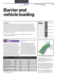
When a <strong>walker</strong> user intends to sit on <strong>the</strong> <strong>walker</strong>,<br />
<strong>the</strong> brakes are applied and <strong>the</strong> user turns around<br />
and sits down (Fig. 1). When <strong>the</strong> user is ready to<br />
walk again, she rises, turns around, unlocks <strong>the</strong><br />
brakes, and continues walking. To examine <strong>the</strong><br />
per<strong>for</strong>mance <strong>of</strong> a parked <strong>walker</strong>, three modes <strong>of</strong>instability<br />
should be considered. The first mode <strong>of</strong>instability<br />
occurs when <strong>the</strong> brakes hold, but <strong>the</strong><br />
wheels slide along <strong>the</strong> ground. The second mode results<br />
when <strong>the</strong> entire <strong>walker</strong> tips over. The third
Downloaded by [University <strong>of</strong> Sheffield] at 14:02 15 February 2012<br />
FIG. 1. Walking with a <strong>walker</strong> (Fig. Ia), and sitting on a<br />
<strong>walker</strong> (Fig. lb),<br />
GUIDE LINE FOR WALKER DESIGN<br />
Braked<br />
wheels<br />
Back \ -<br />
FIG. 2. Distribu tion <strong>of</strong> subject-applied <strong>for</strong>ces.<br />
Front<br />
mode is brake failure, in which <strong>the</strong> brakes cannot<br />
hold <strong>the</strong> wheels and <strong>the</strong>y begin to roll.<br />
Sl iding<br />
When sitting and rising from a parked <strong>walker</strong>,<br />
<strong>the</strong> user applies a <strong>for</strong>ce F to <strong>the</strong> <strong>walker</strong>. A normal<br />
(vertical) <strong>for</strong>ce F z is transmitted through all <strong>four</strong><br />
wheels , and a shear (horizontal) <strong>for</strong>ce F y is transmitted<br />
through th e braked wheels only (Fig. 2).<br />
The normal <strong>for</strong>ce acting through <strong>the</strong> braked<br />
wheel s comprise s a portion <strong>of</strong> <strong>the</strong> <strong>for</strong>ce applied by<br />
<strong>the</strong> user and a portion <strong>of</strong> <strong>the</strong> <strong>walker</strong> weight. If<strong>the</strong><br />
shear <strong>for</strong>ce divided by <strong>the</strong> total normal <strong>for</strong>ce at ei<strong>the</strong>r<br />
<strong>of</strong> <strong>the</strong> braked wheels exceeds <strong>the</strong> coefficient <strong>of</strong><br />
friction between <strong>the</strong> braked wheel and <strong>the</strong> ground,<br />
sliding will result.<br />
Tipping<br />
With <strong>the</strong> braked wheels locked, <strong>the</strong> <strong>walker</strong> can<br />
tip in two directions, as seen in Figure 3. The first<br />
is counterclockwise about <strong>the</strong> contact point <strong>of</strong> <strong>the</strong><br />
braked wheels and <strong>the</strong> ground, caused by a negative<br />
moment M B' and <strong>the</strong> second is clockwise about<br />
<strong>the</strong> axle <strong>of</strong> <strong>the</strong> casters, caused by a positive moment<br />
M F " If <strong>the</strong> user <strong>for</strong>ce is applied behind or in<br />
front <strong>of</strong> <strong>the</strong> wheelbase and creates enough <strong>of</strong>a moment<br />
to overcome <strong>the</strong> weight <strong>of</strong><strong>the</strong> <strong>walker</strong>, tipping<br />
FIG. 3. The two directions <strong>of</strong> tipping.<br />
117
Downloaded by [University <strong>of</strong> Sheffield] at 14:02 15 February 2012<br />
FIG. 6. Normal and shear <strong>for</strong>ces appli ed through plate A and B, resp ectively (Figs. 6a and b), and normal <strong>for</strong>ce applied<br />
through both casters (Fig. 6c).<br />
to rest. During this adjustment, <strong>the</strong> subject could<br />
sit on a stool beside <strong>the</strong> apparatus. Each <strong>of</strong> <strong>the</strong> six<br />
seat positions was tested twice, <strong>for</strong> a total <strong>of</strong> 12 trials.<br />
The entire test took 1 hour.<br />
During <strong>the</strong> rest periods, <strong>the</strong> subjects were asked<br />
two questions: first, whe<strong>the</strong>r <strong>the</strong> <strong>walker</strong> would be<br />
more com<strong>for</strong>table if <strong>the</strong> seat were higher or lower,<br />
or whe<strong>the</strong>r <strong>the</strong>y were com<strong>for</strong>table <strong>the</strong> way it was;<br />
and second, whe<strong>the</strong>r <strong>the</strong>y would be more com<strong>for</strong>table<br />
with <strong>the</strong> <strong>walker</strong>'s handles fur<strong>the</strong>r toward <strong>the</strong><br />
back or toward <strong>the</strong> front.<br />
GUIDELINE FOR WALKER DESIGN<br />
RESULTS AND DISCUSSION<br />
A typical example <strong>of</strong> <strong>the</strong> <strong>for</strong>ces recorded while<br />
one subject sat down and <strong>the</strong>n stood up <strong>for</strong> one trial<br />
is shown in Figure 6. Figures 6a and b show <strong>the</strong><br />
normal and shear <strong>for</strong>ces applied at each <strong>of</strong> <strong>the</strong><br />
braked wheels, and Figure 6c shows <strong>the</strong> normal<br />
<strong>for</strong>ce applied at <strong>the</strong> two casters.<br />
The responses to <strong>the</strong> questions regarding <strong>the</strong><br />
com<strong>for</strong>t <strong>of</strong> <strong>the</strong> handle and <strong>the</strong> seat are summarized<br />
in Table 1. Varying <strong>the</strong> handle position <strong>for</strong> a fixed<br />
119
Downloaded by [University <strong>of</strong> Sheffield] at 14:02 15 February 2012<br />
ping and sliding modes <strong>of</strong> instability. These tables<br />
can be applied to <strong>walker</strong> <strong>design</strong>s to evaluate per<strong>for</strong>mance<br />
or aid in <strong>design</strong> decision making.<br />
The data imply that most present-day <strong>walker</strong>s<br />
are potentially dangerous when used as seats. Existing<br />
models may slide along <strong>the</strong> ground or tip<br />
backward or <strong>for</strong>ward, causing, at best, anxiety,<br />
and at worst, injury. These results suggest that to<br />
create a safer mobility aid, <strong>the</strong> seat and center <strong>of</strong><br />
gravity should be placed closer to <strong>the</strong> braked<br />
wheels. This will transmit greater normal <strong>for</strong>ces<br />
through <strong>the</strong> braked wheels, and less sliding will result.<br />
This study, however, was limited to examination<br />
<strong>of</strong> <strong>the</strong> static stability <strong>of</strong> <strong>walker</strong>s during sitting/standing<br />
transfers, and <strong>the</strong> compatibility <strong>of</strong><br />
our recommendations with safe dynamic per<strong>for</strong>-<br />
APPENDIX A<br />
This appendix presents six sets <strong>of</strong> <strong>design</strong> tables.<br />
Each set corresponds to one <strong>of</strong> six configurations<br />
(seat height and handle position) tested. A total <strong>of</strong><br />
<strong>four</strong> tables are included in each set corresponding<br />
to <strong>walker</strong>s with wheelbases <strong>of</strong> 40 em and 50 em,<br />
Wheel base " 40 em<br />
-20 -10 0<br />
sIb<br />
10 20 30 40 50<br />
10 + + 19 + + + + +<br />
20 + + + + + + + +<br />
elb 30 + + + + + + + +<br />
40 + + + + + + + +<br />
50 + + + + + + + +<br />
60 + + + + + + + +<br />
70 + + + + + + + +<br />
Wheel base" 50 em<br />
-20 ·10 0<br />
sIb<br />
10 20 30 40 50<br />
10 + + 18 18 + + + +<br />
20 + + 17 19 + + + +<br />
elb 30 + + 19 + + + + +<br />
40 + 19 + + + + + +<br />
50 + + + + + + + +<br />
60 + + + + + + + +<br />
70 + + + + + + + +<br />
Configuration #1<br />
mance during walking requires confirmation. Rising<br />
was considered only when <strong>the</strong> user was seated<br />
in <strong>the</strong> <strong>walker</strong>. Forces applied through <strong>the</strong> <strong>walker</strong><br />
when using it as an aid in rising from ano<strong>the</strong>r chair<br />
or <strong>the</strong> end <strong>of</strong> a bed were not examined.<br />
Acknowledgments: This research was supported<br />
in part by <strong>the</strong> Ontario Rehabilitation Technology<br />
Consortium, which is funded by <strong>the</strong> Ministry <strong>of</strong><br />
Health <strong>of</strong> Ontario, Canada.<br />
REFERENCES<br />
Hall , J ., Clarke, A. K., & Harrison, R. (1990). Guidelines <strong>for</strong><br />
prescription <strong>of</strong> walkin g frames. Physio<strong>the</strong>rapy, 76, 118-1 20.<br />
Statistics Canada. (1991). Health and activi ty limitation survey<br />
(1991). Ottawa: Statistics Canada.<br />
equipped with low friction ( J..L = 0.4) and high friction<br />
(J..L = 0.8) wheels. Each table shows <strong>the</strong> minimum<br />
safe <strong>walker</strong> weights (kg) corresponding to<br />
different locations <strong>of</strong><strong>the</strong> seat (sib) and <strong>of</strong><strong>the</strong> center<br />
<strong>of</strong> gravity <strong>of</strong> <strong>the</strong> <strong>walker</strong> (c/b).<br />
Wheel base " 40 em<br />
-20 -'0 0<br />
sIb<br />
10 20 30 40 50<br />
10 + + 16 18 + + + +<br />
20 + + 16 19 + + + +<br />
elb 30 + + 17 + + + + +<br />
40 + 18 18 + + + + +<br />
50 + 16 19 + + + + +<br />
60 + 18 + + + + + +<br />
70 + 19 + + + + + +<br />
Wheel bas e " 50 em<br />
-20 -10 0<br />
sIb<br />
10 20 30 40 50<br />
10 + + 18 13 15 18 + +<br />
20 + + 12 13 16 19 + +<br />
elb 30 + + 11 14 16 19 + +<br />
40 + 19 12 15 18 + + +<br />
50 + 16 13 16 19 + + +<br />
60 + 14 14 18 + + + +<br />
70 + 14 16 19 + + + +<br />
GUIDELINE FOR WALKER DESIGN 123
Downloaded by [University <strong>of</strong> Sheffield] at 14:02 15 February 2012<br />
e/b<br />
e/b<br />
Configuration #2<br />
Wheel base = 40 em Wheel base = 40 em<br />
sib<br />
-20 ·10 0 10 20 30 40 50<br />
10 12 13 14 15 16 18 19 +<br />
20 13 14 15 16 18 19 + +<br />
30 14 15 16 18 19 + + +<br />
40 15 16 18 19 + + + +<br />
50 16 18 19 + + + + +<br />
60 18 19 + + + + + +<br />
70 19 + + + + + + +<br />
Wheel base = 50 em Wheel base =50 em<br />
sib<br />
-20 ·10 0 10 20 30 40 50<br />
10 18 12 13 14 14 16 18 19<br />
20 11 13 14 14 16 17 19 +<br />
30 13 13 14 16 17 19 + +<br />
40 13 14 16 17 19 + + +<br />
50 14 16 17 19 + + + +<br />
60 16 18 19 + + + + +<br />
70 18 19 + + + + + +<br />
Configuration #3<br />
u =0.4 u =0.8<br />
Wheel base =40 em Wheel base =40 em<br />
20 30 40 50 50<br />
11 13 16 + +<br />
11 14 17 + +<br />
e/b 13 15 18 + e/b +<br />
13 16 19 + +<br />
14 18 + + +<br />
16 19 + + +<br />
18 + + + +<br />
Wheel base =50 em Wheel base =50 em<br />
30 40 50<br />
11 14 16<br />
12 14 18<br />
e/b 13 16 19 e/b<br />
14 17 +<br />
15 19 +<br />
16 + +<br />
19 + +<br />
124 ASSISTlVE TECHNOLOGY, VOL. 9, NO.2
Downloaded by [University <strong>of</strong> Sheffield] at 14:02 15 February 2012<br />
where a is <strong>the</strong> acceleration <strong>of</strong> <strong>the</strong> wheel. All variables<br />
are known except this acceleration. Isolating<br />
<strong>for</strong> <strong>the</strong> acceleration,<br />
a = A y - WAz/w/2g. (8)<br />
For uni<strong>for</strong>m acceleration (a = const.) over a small<br />
interval <strong>of</strong> time t,<br />
For <strong>the</strong> case <strong>of</strong><strong>the</strong> wheel not contacting <strong>the</strong> ground<br />
(Fz = 0),<br />
Converging on a Design Parameter<br />
(9)<br />
where d, is an incremental distance slid over a<br />
small interval <strong>of</strong> time. Assuming V o = 0 over this<br />
short time span with constant acceleration,<br />
r, = w/ zg 'a<br />
a = Fylw/2g'<br />
(10)<br />
(11)<br />
(12)<br />
Once acceleration is determined, <strong>the</strong> distance can<br />
be calculated. The distance that <strong>the</strong> mass moves<br />
between each data point can <strong>the</strong>n be summed <strong>for</strong><br />
<strong>the</strong> total slide distance. Dangerous sliding can occur<br />
at ei<strong>the</strong>r <strong>of</strong> <strong>the</strong> braked wheels at two points<br />
during <strong>the</strong> trial, sitting down and <strong>the</strong>n standing<br />
up. The maximum <strong>of</strong> <strong>the</strong>se <strong>four</strong> sliding distances<br />
was set to 5 em. This distance is large enough not<br />
to demand extreme <strong>walker</strong> <strong>design</strong>s, yet small<br />
enough not to cause stress to <strong>the</strong> user while sitting.<br />
The above calculations can be used to find <strong>the</strong><br />
relationship between any two variables if<strong>the</strong> o<strong>the</strong>r<br />
five are known. For example, if <strong>the</strong> effect <strong>of</strong> <strong>the</strong><br />
seat position on <strong>the</strong> required <strong>walker</strong> mass must be<br />
determined, all o<strong>the</strong>r variables are held constant,<br />
and an iterative procedure can be per<strong>for</strong>med <strong>for</strong><br />
each <strong>walker</strong> mass to isolate <strong>the</strong> seat position that<br />
will allow <strong>for</strong> <strong>the</strong> desired maximum sliding distance.<br />
Any seat position behind this value will be<br />
a safe <strong>design</strong> with respect to sliding, while positions<br />
fur<strong>the</strong>r to <strong>the</strong> front will cause excessive sliding.<br />
The bisection method was used to converge on<br />
desired values to within 5%.<br />
Tipping<br />
Ifat any time <strong>the</strong> applied <strong>for</strong>ce vector and <strong>walker</strong><br />
weight combine <strong>for</strong> a resultant <strong>for</strong>ce outside <strong>of</strong><br />
<strong>the</strong> wheelbase, <strong>the</strong> wheels will begin to rise <strong>of</strong>f<strong>the</strong><br />
ground. The only opposing <strong>for</strong>ce that will help to<br />
maintain <strong>the</strong> stability <strong>of</strong> <strong>the</strong> <strong>walker</strong> is <strong>the</strong> <strong>walker</strong><br />
weight. As long as <strong>the</strong> resultant <strong>of</strong> <strong>the</strong> combined<br />
<strong>walker</strong> weight Wand applied <strong>for</strong>ce F are contained<br />
within <strong>the</strong> wheelbase, tipping will be avoided. Five<br />
<strong>of</strong><strong>the</strong> <strong>design</strong> variables affect tipping: seat position,<br />
wheelbase, <strong>walker</strong> mass, center <strong>of</strong> gravity, and<br />
configuration. For example, a larger wheel base reduces<br />
<strong>the</strong> tipping moment caused by <strong>the</strong> <strong>for</strong>ces applied<br />
outside <strong>of</strong> <strong>the</strong> wheelbase by shortening <strong>the</strong><br />
distances that <strong>the</strong>y are acting from <strong>the</strong> wheels. The<br />
position <strong>of</strong> <strong>the</strong> center <strong>of</strong> gravity <strong>of</strong> <strong>the</strong> <strong>walker</strong> will<br />
control how great a stabilizing moment <strong>the</strong> <strong>walker</strong><br />
weight will cause about <strong>the</strong> wheels. Moment calculations<br />
were per<strong>for</strong>med to estimate <strong>design</strong> variables<br />
that would allow <strong>for</strong> a 2-cm rise <strong>of</strong> ei<strong>the</strong>r <strong>the</strong><br />
braked wheels or <strong>the</strong> casters.<br />
Brake Failure<br />
Brake failure can occur only when <strong>the</strong>re is<br />
enough normal <strong>for</strong>ce acting through <strong>the</strong> braked<br />
wheels to avoid sliding. If <strong>the</strong> shear (horizontal)<br />
<strong>for</strong>ce applied to ei<strong>the</strong>r <strong>of</strong><strong>the</strong> braked wheels creates<br />
enough <strong>of</strong> a shear stress at <strong>the</strong> brake pad to exceed<br />
<strong>the</strong> grip <strong>of</strong> <strong>the</strong> brake on <strong>the</strong> tire, <strong>the</strong> wheels will<br />
roll. As in sliding, small movements <strong>of</strong> <strong>the</strong> <strong>walker</strong><br />
will go unnoticed by <strong>the</strong> user. Figure B6 shows <strong>the</strong><br />
shear <strong>for</strong>ce applied by <strong>the</strong> user through one braked<br />
wheel over an entire trial. The horizontal line represents<br />
<strong>the</strong> shear that <strong>the</strong> brake can withstand<br />
without allowing rolling. The portion <strong>of</strong> <strong>the</strong> curve<br />
above this line indicates rolling. The maximum<br />
shear <strong>for</strong>ce that allows less than 5 em (2 in.) <strong>of</strong> rolling<br />
must be found to avoid significant brake failure.<br />
Design variables that will affect brake failure<br />
are <strong>the</strong> seat-handle configuration and <strong>the</strong> <strong>walker</strong><br />
mass. As <strong>the</strong> <strong>walker</strong> mass increases, <strong>the</strong>re is a<br />
greater load to accelerate, resulting in less movement.<br />
Calculations similar to <strong>the</strong> sliding analysis<br />
were <strong>the</strong>n per<strong>for</strong>med to estimate <strong>design</strong> variables<br />
that would allow <strong>for</strong> a 5-cm roll <strong>of</strong> ei<strong>the</strong>r <strong>of</strong> <strong>the</strong><br />
braked wheels.<br />
GUIDELINE FOR WALKER DESIGN 129