Netgear ProSafe VPN firewall (FVS318 or FVM318) - VPN Case ...
Netgear ProSafe VPN firewall (FVS318 or FVM318) - VPN Case ...
Netgear ProSafe VPN firewall (FVS318 or FVM318) - VPN Case ...

You also want an ePaper? Increase the reach of your titles
YUMPU automatically turns print PDFs into web optimized ePapers that Google loves.
<strong>Netgear</strong> <strong>ProSafe</strong> <strong>VPN</strong> <strong>firewall</strong> (<strong>FVS318</strong> <strong>or</strong> <strong>FVM318</strong>) to Cisco PIX <strong>firewall</strong><br />
This document is a step-by-step instruction f<strong>or</strong> setting up <strong>VPN</strong> between <strong>Netgear</strong> <strong>ProSafe</strong><br />
<strong>VPN</strong> <strong>firewall</strong> (<strong>FVS318</strong> <strong>or</strong> <strong>FVM318</strong>) and Cisco PIX <strong>firewall</strong>.<br />
The instruction is verified with <strong>FVS318</strong> (firmware version v2.4), <strong>FVM318</strong> (firmware<br />
version R1.2 Beta) and Cisco PIX 501 (firmware 6.3.3 and Pix Device Manager PDM<br />
3.0).<br />
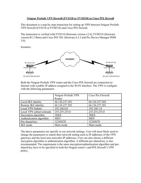
Scenario:<br />
66.126.237.201<br />
Ethernet<br />
INTERNET<br />
<strong>ProSafe</strong> <strong>VPN</strong> router Cisco PIX <strong>firewall</strong><br />
192.168.0.0/255.255.255.0<br />
66.126.237.202<br />
Ethernet<br />
192.168.1.0/255.255.255.0<br />
Both the <strong>Netgear</strong> <strong>ProSafe</strong> <strong>VPN</strong> router and the Cisco PIX <strong>firewall</strong> are connection to<br />
Internet with a public IP address assigned to the WAN interface. The <strong>VPN</strong> is configure<br />
with the following parameters:<br />
<strong>Netgear</strong> <strong>ProSafe</strong> <strong>VPN</strong><br />
Router<br />
Cisco Pix Firewall<br />
Local IKE identity 66.126.237.201 66.126.237.202<br />
Remote IKE identity 66.126.237.202 66.126.237.201<br />
Local <strong>VPN</strong> Subnet 192.168.0.0 192.168.1.0<br />
Local <strong>VPN</strong> subnet netmask 255.255.255.0 255.255.255.0<br />
Encryption alg<strong>or</strong>ithm 3DES 3DES<br />
Authentication alg<strong>or</strong>ithm MD5 MD5<br />
Pre-shared key 12345678 12345678<br />
IKE mode Main mode Main mode<br />
The above parameters are specific to our netw<strong>or</strong>k settings. User will most likely need to<br />
change the parameters to match their netw<strong>or</strong>k setting such as IP addresses of the <strong>VPN</strong><br />
gateways and the local area netw<strong>or</strong>ks IP addresses. User can also choose a different<br />
encryption alg<strong>or</strong>ithm <strong>or</strong> authentication alg<strong>or</strong>ithm. A different pre-shared key is also<br />
recommended. The requirement is the same encryption/authentication alg<strong>or</strong>ithm and preshared<br />
key have to be specified in both the <strong>Netgear</strong> router’s and PIX <strong>firewall</strong>’s <strong>VPN</strong><br />
policy.
I. Configure the <strong>Netgear</strong> <strong>ProSafe</strong> <strong>VPN</strong> router:<br />
1. Log in to the <strong>Netgear</strong> <strong>ProSafe</strong> <strong>VPN</strong> router.<br />
2. Click on <strong>VPN</strong> Setting under the Setup menu. Choose one of the unused policies<br />
and click Edit.<br />
a. Enter a descriptive name f<strong>or</strong> the <strong>VPN</strong> policy in the Connection<br />
Name textbox. It is only being used to help user manage the<br />
<strong>VPN</strong> polices. F<strong>or</strong> our example, PIX<strong>VPN</strong>.<br />
b. In the Local IPSEC Identifier textbox, enter the WAN IP address<br />
of the <strong>Netgear</strong> router.<br />
c. In the Remote IPSec Identifier textbox, enter the WAN IP<br />
address of the PIX <strong>firewall</strong><br />
d. In the Tunnel can be accessed from box, choose a subnet of<br />
local address. Enter the LAN IP address of the <strong>Netgear</strong> router<br />
f<strong>or</strong> Local LAN start IP Address. Enter the LAN subnet mask<br />
f<strong>or</strong> Local LAN IP Subnetmask. IP inf<strong>or</strong>mation can be looked<br />
up from the LAN IP Setup menu.<br />
e. In the Tunnel can access box, choose a subnet of remote<br />
address. F<strong>or</strong> Remote LAN start IP address, enter the LAN IP<br />
subnet behind the PIX <strong>firewall</strong>. F<strong>or</strong> Remote LAN IP<br />
Subnetmask, enter the subnet mask of the LAN IP subnet behind<br />
the PIX <strong>firewall</strong>.<br />
f. In the Remote WAN IP <strong>or</strong> FQDN box, enter the PIX <strong>firewall</strong>’s<br />
WAN IP address.<br />
g. F<strong>or</strong> Secure Association, choose Main Mode.<br />
h. F<strong>or</strong> Perfect F<strong>or</strong>ward Secrecy, check Disabled.<br />
i. F<strong>or</strong> Encryption Protocol, choose 3DES.<br />
j. F<strong>or</strong> Pre-shared Key, enter the pre-shared key “12345678”.<br />
k. Enter 28800 seconds f<strong>or</strong> Key Life.<br />
l. Enter 86400 f<strong>or</strong> IKE Life Time.<br />
m. Check the box NETABIOS Enable.<br />
n. Click Apply.
There are three methods of creating <strong>VPN</strong> policy with a PIX <strong>firewall</strong> – command line<br />
interface, <strong>VPN</strong> configuration page within the PDM, <strong>VPN</strong> wizard within the PDM. We<br />
will describe step-by-step instruction f<strong>or</strong> all three methods.<br />
The instruction is tested with the PIX <strong>firewall</strong> in its fact<strong>or</strong>y default setting. We have only<br />
configured the <strong>firewall</strong>’s WAN interface IP address and the default gateway bef<strong>or</strong>e<br />
setting up <strong>VPN</strong> policy. Your PIX <strong>firewall</strong> may have existing configurations that need to<br />
be modified in <strong>or</strong>der f<strong>or</strong> the <strong>VPN</strong> to w<strong>or</strong>k. F<strong>or</strong> example, <strong>firewall</strong> rules and NAT (netw<strong>or</strong>k<br />
address translation) rules may interfere with your <strong>VPN</strong>. Please refer to your Cisco<br />
documentation f<strong>or</strong> configuring those settings.<br />
From the Cisco PIX command line interface:<br />
1. Log into the command line interface through either console, telnet <strong>or</strong> ssh.<br />
2. Type enable to enter enable mode. Enter your passw<strong>or</strong>d when prompted.<br />
3. Type config t to enter configuration mode.
4. Create a name object f<strong>or</strong> your local netw<strong>or</strong>k – 192.168.0.0 in our example.<br />
name 192.168.0.0 remote<strong>VPN</strong><br />
5. Create an access list to exclude from NAT, the access should specific traffic from<br />
your local netw<strong>or</strong>k to the remote netw<strong>or</strong>k.<br />
access-list inside_nat0_outbound permit ip 192.168.1.0 255.255.255.0<br />
remote<strong>VPN</strong> 255.255.255.0<br />
6. Create an access list defining the traffic to be encrypted by the <strong>VPN</strong>.<br />
access-list outside_cryptomap_20 permit ip 192.168.1.0 255.255.255.0<br />
remote<strong>VPN</strong> 255.255.255.0<br />
7. Create a NAT rule to not translate traffic between your local netw<strong>or</strong>k and the<br />
remote netw<strong>or</strong>k.<br />
nat (inside) 0 access-list inside_nat0_outbound<br />
8. Enable IPSEC traffic to be permitted from the Internet.<br />
sysopt connection permit-ipsec<br />
9. Create a transf<strong>or</strong>m set with the encryption and authentication alg<strong>or</strong>ithms you have<br />
chosen.<br />
crypto ipsec transf<strong>or</strong>m-set ESP-3DES-MD5 esp-3des esp-md5-hmac<br />
10. Create a crypt map using IPSEC ISAKMP.<br />
crypto map outside_map 20 ipsec-isakmp<br />
11. Specify your <strong>VPN</strong> traffic, defined in step(6), f<strong>or</strong> the crypto map.<br />
crypto map outside_map 20 match address outside_cryptomap_20<br />
12. Specify the <strong>VPN</strong> peer – the <strong>Netgear</strong> router.<br />
crypto map outside_map 20 set peer 66.126.237.201<br />
13. Specify the transf<strong>or</strong>m set – created in step (9).<br />
crypto map outside_map 20 set transf<strong>or</strong>m-set ESP-3DES-MD5<br />
14. Apply the crypto map to the outside interface.<br />
crypto map outside_map interface outside<br />
15. Enter the IKE parameters.<br />
isakmp enable outside<br />
isakmp policy 10 authentication pre-share<br />
isakmp policy 10 encryption 3des<br />
isakmp policy 10 hash md5<br />
isakmp policy 10 group 2<br />
isakmp policy 10 lifetime 86400<br />
16. Define your pre-shared key. “12345678” in our example.<br />
isakmp key ******** address 66.126.237.201 netmask 255.255.255.255<br />
no-xauth no-config-mode<br />
17. Type exit to quit from configuration mode.<br />
18. Type write mem to save the configuration into flash mem<strong>or</strong>y.<br />
From the <strong>VPN</strong> configuration page in the PDM:<br />
1. Under Categ<strong>or</strong>ies, Click on IKE -> Policies and click on Add to add new IKE<br />
policy. Enter 10 as Pri<strong>or</strong>ity. Choose pre-share as Authentication, 3des as<br />
Encryption, 2 as D-H Group, md5 as Hask and 86400 seconds as Lifetime. Click<br />
OK.
Under General inf<strong>or</strong>mation, highlight outside interface and click Enable.<br />
Click Apply.
2. Choose Pre-shared Key under IKE. Click Add to add a new pre-share key. Enter<br />
66.126.237.201 as Peer IP, 255.255.255.255 as Netmask, enter the pre-share key<br />
twice and check both the box f<strong>or</strong> no-xauth and no-config-mode. Click OK.
Click Apply.
3. Choose <strong>VPN</strong> System Options, check Bypass access check f<strong>or</strong> IPSec and L2TP<br />
traffic. Click Apply.<br />
4. Highlight IPSec Rules under IPSec. Pull down the Rules menu and choose Add to<br />
add new IPSec Rule.
5. Click on the New button next to Tunnel Policy. Choose outside as Interface,<br />
choose static as Type, enter 10 as Pri<strong>or</strong>ity, choose ESP-3DES-MD5 as Transf<strong>or</strong>m<br />
Set. Enter 66.126.237.201 as Peer IP Address and left the other parameter
unchanged.
6. Choose protect under Action. Under Firewall Side Host/Netw<strong>or</strong>k, choose IP<br />
Address, choose inside as Interface, enter 192.168.1.0 as IP address and<br />
255.255.255.0 as Mask. Under Remote Side Host/Netw<strong>or</strong>k, choose IP Address,<br />
choose outside as Interface, enter 192.168.0.0 as IP address and 255.255.255.0 as<br />
Mask. Under Protocol and Service, choose IP and any as IP protocol. Check the<br />
box Exempt PIX side host/netw<strong>or</strong>k from address translation. In the description<br />
box, enter a description f<strong>or</strong> this IPSec rule. Click OK.<br />
7. When ask to Add host/netw<strong>or</strong>k, Click OK.
8. Enter a name to identify the netw<strong>or</strong>k and click Next.<br />
9. When ask about defining static route, just click Next.
10. Click Finish to finish creating netw<strong>or</strong>k.
11. The IPSec Policy is created. Click Apply.
From <strong>VPN</strong> wizard in the PDM (choose <strong>VPN</strong> wizard from the Wizard pull down menu):
1. Select Site to Site <strong>VPN</strong> as type of <strong>VPN</strong>. Select outside as the interface on which<br />
the PVN will be enable.
2. Enter 66.126.237.201 as Peer IP Address. Under Authentication, enter the Preshared<br />
key twice. Click Next.
3. Select 3DES as Encryption alg<strong>or</strong>ithm, select MD5 as Authentication alg<strong>or</strong>ithm<br />
and select Group 2 as DH Group. Click Next.
4. Select 3DES as Encryption alg<strong>or</strong>ithm. Select MD5 as Authentication alg<strong>or</strong>ithm.<br />
Click Next.
5. Select IP Address. Select inside as the interface. Enter 192.168.1.0 as IP address.<br />
Enter 255.255.255.0 as mask. Click on the >> button. Click Next.
6. Select IP Address. Select outside as the Interface. Enter 192.168.0.0 as IP address.<br />
Enter 255.255.255.0 as Mask. Click on the >> button. Click Next.<br />
7. When prompted to Add host/netw<strong>or</strong>k, click OK.<br />
8. Enter a name f<strong>or</strong> the new netw<strong>or</strong>k. Click Next.
9. Click Finish to create the netw<strong>or</strong>k.<br />
10. Click Finish to create the <strong>VPN</strong> connection.
.<br />
Troubleshooting