AT90USBKey Basic Programming and Configuration
AT90USBKey Basic Programming and Configuration
AT90USBKey Basic Programming and Configuration

You also want an ePaper? Increase the reach of your titles
YUMPU automatically turns print PDFs into web optimized ePapers that Google loves.
<strong>AT90USBKey</strong> – <strong>Basic</strong> <strong>Programming</strong> <strong>Configuration</strong> for MS Windows Environments<br />
(By Alex<strong>and</strong>er Hoole, v0.1, September 2006)<br />
Table of Contents<br />
Introduction ....................................................................................................................................1<br />
Hardware summary.........................................................................................................................1<br />
Getting started ................................................................................................................................2<br />
Setup for programming...................................................................................................................2<br />
Installing WinAVR ...............................................................................................................3<br />
Installing AVR Studio 4........................................................................................................3<br />
Installing FLIP ......................................................................................................................3<br />
Final Preparation ............................................................................................................................4<br />
Creating your first AVR Studio project..........................................................................................6<br />
Adding the source .................................................................................................................6<br />
Building the project...............................................................................................................8<br />
Loading your first program on the key using FLIP ........................................................................8<br />
Closing Remarks ............................................................................................................................8<br />
Introduction<br />
This short document is intended to give a quick walkthrough of the tools <strong>and</strong> basic steps required<br />
to start working with the ATMEL <strong>AT90USBKey</strong>. There is a host of programs, tools <strong>and</strong><br />
examples available, however, there did not seem to be any sort of documentation that gave a fast<br />
introduction to what is needed to get things up <strong>and</strong> running. Hopefully you will find this<br />
collection of steps helpful in getting your project up <strong>and</strong> going.<br />
Hardware summary<br />
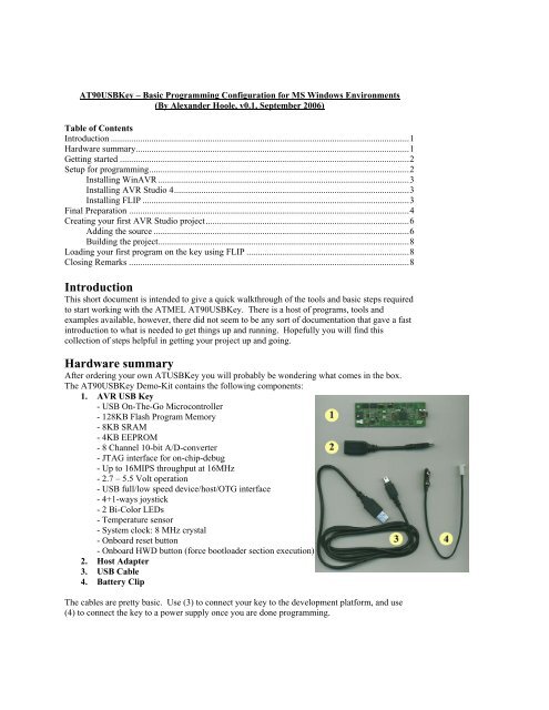
After ordering your own ATUSBKey you will probably be wondering what comes in the box.<br />
The <strong>AT90USBKey</strong> Demo-Kit contains the following components:<br />
1. AVR USB Key<br />
- USB On-The-Go Microcontroller<br />
- 128KB Flash Program Memory<br />
- 8KB SRAM<br />
- 4KB EEPROM<br />
- 8 Channel 10-bit A/D-converter<br />
- JTAG interface for on-chip-debug<br />
- Up to 16MIPS throughput at 16MHz<br />
- 2.7 – 5.5 Volt operation<br />
- USB full/low speed device/host/OTG interface<br />
- 4+1-ways joystick<br />
- 2 Bi-Color LEDs<br />
- Temperature sensor<br />
- System clock: 8 MHz crystal<br />
- Onboard reset button<br />
- Onboard HWD button (force bootloader section execution)<br />
2. Host Adapter<br />
3. USB Cable<br />
4. Battery Clip<br />
The cables are pretty basic. Use (3) to connect your key to the development platform, <strong>and</strong> use<br />
(4) to connect the key to a power supply once you are done programming.
The USB key, however, is more complicated <strong>and</strong> deserves to have its key components spelled<br />
out. The AVR USB Key has the following layout:<br />
LABEL Description<br />
A-F Ports A through F<br />
G USB MiniAB connector<br />
H JTAG port<br />
I-J Bi-colored LEDs (Red/Green LEDs)<br />
K Power LED<br />
L External power connector<br />
M 4+1 way joystick (four directions + push button)<br />
N On board reset button<br />
O On board HWB button to force bootloader section execution on reset<br />
P Data flash memory<br />
Q Temperature sensor<br />
R AT90USB1287<br />
Note: For additional information refer to the “<strong>AT90USBKey</strong> Hardware User Guide”.<br />
While the kit does not contain connectors for ports [A-F] or the JTAG port, you will hopefully be<br />
able to obtain them during the course.<br />
In this short tutorial we will make use of the following features:<br />
Use (G) to connect to our development machine<br />
Use (N) <strong>and</strong> (O) to change the operating mode of the key <strong>and</strong> to run our software<br />
once it is uploaded onto the key<br />
Use our software to have (I) <strong>and</strong> (J) LEDs light up.<br />
Getting started<br />
First, attach the USB key (1) to the USB port of your PC/Laptop using the USB cable (3). Once<br />
the USB key is attached, the operating system should detect the presence of a new device <strong>and</strong><br />
grant access to the USB key via a new drive letter on your machine. You should start by opening<br />
this new drive <strong>and</strong> then double-click on index.html to start learning the new device.<br />
Setup for programming<br />
To program our <strong>AT90USBKey</strong> we will need a combination of software. The following setup<br />
was performed on a Intel based Windows XP Professional machine.
In general, the software available for programming the <strong>AT90USBKey</strong> is listed at the following<br />
URL: http://www.atmel.com/dyn/products/product_card.asp?part_id=3875. We will make use<br />
of WinAVR, which provides the GCC compiler that we will use; AVR Studio 4, which provides<br />
the integrated development environment we will develop on; <strong>and</strong> FLIP 3, which will be used to<br />
load our new programs onto the USB key. In the following section we will quickly follow the<br />
necessary steps to configure the development machine.<br />
Installing WinAVR<br />
Download <strong>and</strong> install WinAVR from the following URL: http://winavr.sourceforge.net.<br />
Note: Available for all 32-bit MS Windows (95/98/NT/2000/XP).<br />
Installing AVR Studio 4<br />
Download <strong>and</strong> install AVR Studio 4 <strong>and</strong> Service Pack 3 from the following URL:<br />
http://www.atmel.com/dyn/products/tools_card.asp?tool_id=2725. Make sure you choose the<br />
“Install/upgrade USB Driver” option if you plan to use JTAG later on.<br />
Note: Available for MS Windows 95/98/NT/2000/XP.<br />
Installing FLIP<br />
Download <strong>and</strong> install FLIP 3 from the following URL:<br />
http://www.atmel.com/dyn/products/tools_card.asp?tool_id=3886. Once completed you will<br />
need to reboot your machine.<br />
FLIP st<strong>and</strong>s for Flexible In-system Programmer <strong>and</strong> it allows us to program all of the FLASH<br />
C51 parts. During installation the following list of features is provided is provided:<br />
Performs In-System <strong>Programming</strong> through RS232, USB or CAN interfaces.<br />
May be used through its intuitive Graphical User Interface or launched from a DOS<br />
window (see the batchisp manual), from an embedded software IDE like KEIL's<br />
uVision2, or even from your own application (see the ISP Functions Library<br />
manual).<br />
Runs under Windows 9x / Me / NT / 2000 / XP.<br />
Supports Intel MCS-86 Hexadecimal Object, Code 88 file format for data file<br />
loading <strong>and</strong> saving.<br />
Buffer editing capabilities: fill, search, copy, reset, modify, goto.<br />
Target device memory control: erase, blank check, program, verify, read, security<br />
level <strong>and</strong> special bytes reading <strong>and</strong> setting.<br />
Parts serialization capability (from batchisp only).<br />
AutoISP allows ISP hardware conditions to be set by software.<br />
The demo mode emulates ISP operations without any target hardware.<br />
The debug mode lets you log the traffic on the selected medium.<br />
On-line help.
Final Preparation<br />
When you are ready to start programming the device you will need to do a hard reset of the<br />
<strong>AT90USBKey</strong>. To do a hard reset of the key do the following:<br />
Press both “RST” <strong>and</strong> “HWB” push buttons down simultaneously<br />
First release the “RST” push button<br />
Then release the “HWB” push button<br />
When this is done one of the following will likely occur:<br />
a) You will be prompted for drivers for the new device.<br />
b) The system will already support the device.<br />
Case (b) is most likely going to occur if the device is left in its original configuration. To ensure<br />
that the device is in fact connected <strong>and</strong> detected, check the listing of devices on your machine.<br />
To do this on Windows XP, do the following:<br />
Select: StartRun<br />
Type: compmgmt.msc /s<br />
Click: Ok<br />
Select: Device Manager<br />
Shown below are three screen captures depicting what your device listings will look like in the<br />
three possible states when working with the <strong>AT90USBKey</strong>. The figure on the left shows the<br />
system when the key has initially been plugged in. The figure in the center shows a machine that<br />
does not have the device detected properly for programming (after a hard reset of the key).<br />
Notice the other device with the “?” beside it. The figure on the right does have the device<br />
detected properly for programming (after a hard reset of the key). Notice the addition of the<br />
“Jungo” device. If you do not have this listed, the drivers are not properly installed.<br />
The drivers are located in the subdirectories of the FLIP 3 installation (Ex. C:\Program<br />
Files\Atmel\FLIP 3.0.4\usb). Use this location to provide the drivers for the USB key when<br />
prompted as in (a). From now on you should no longer be prompted for drivers.<br />
Note: Before placing your new program on the key, first copy the existing files from the memory<br />
of the key to a backup folder. This will ensure that you can reload existing HEX files back onto<br />
the device if your program does not work (see files on key: starterkits\STK525-<br />
USBKEY\firmware\hex\*).
Note: The first capture shows the system with the key acting as a normal USB key. The second caption displays the system after the hard reset of the<br />
key (without the drivers installed). The third caption shows the system after the driver from FLIP has been installed for the USB key.
Creating your first AVR Studio project<br />
One of the key features of this IDE is the ability to simulate the different AVR controllers. To setup a programming<br />
project for the <strong>AT90USBKey</strong> follow the following example (remember you could just do this at the comm<strong>and</strong> line<br />
using WinAVR tools):<br />
-Project->Project Wizard<br />
-New Project<br />
-Select: AVR GCC<br />
-Project name: FLASH_LED_DEMO<br />
-Click Next<br />
-Select Debug Platform: AVR Simulator<br />
-Select Device: AT90USB1287<br />
-Click Finish.<br />
Adding the source<br />
Once the project is created you can start writing code to control the hardware on the <strong>AT90USBKey</strong>. Here is a<br />
simple C program that will turn on all the LEDs (read the document doc7627.pdf for information on why we use<br />
port D).<br />
#include <br />
#include <br />
int main (int argc, char *argv[])<br />
{<br />
DDRD = 0xff; /* Set all pins on port D for output<br />
PORTD = 0xff; /* Initialize port to high --- turn on LED<br />
}<br />
return 0;<br />
Note: The header files that you should start learning are located in the following location:<br />
C:\WinAVR\avr\include\avr.<br />
The following Makefile is derived from the CDC project on the CD provided by Mantis. It is documented to define<br />
most of the rules, however, you will probably need to read additional documentation from the following sources:<br />
http://www.gnu.org/software/make/manual/make.html<br />
C:\WinAVR\doc\binutils\index.html<br />
C:\WinAVR\doc\gcc\gcc.pdf<br />
To add the Makefile, right-click on the Other Files folder in the AVR GCC tab (located by default at the left-side of<br />
your screen) <strong>and</strong> choose Create New File. Ensure that you have the Makefile displayed in your AVR GCC tab under<br />
Other Files.<br />
#--- General Flags<br />
PROJECT = FLASH_LED_DEMO #Project name<br />
MCU = at90usb1287 #Target architecture<br />
TARGET = FLASH_LED_DEMO.elf #Target file<br />
CC = avr-gcc.exe #Compiler for C files<br />
#--- Options common to compile, link <strong>and</strong> assembly rules<br />
COMMON = -mmcu=$(MCU) #Compile for target arch.
#--- Compile options common for all C compilation units.<br />
# -D Predefine as macro<br />
# -Wall Enable all optional warnings<br />
# -gdwarf-2 Produce debugging information in DWARF format (version 2)<br />
# -Os Optimize for size<br />
# -fsigned-char Let type char be signed<br />
# -MD -MP –MT -MF Specify where dependencies are written<br />
CFLAGS = $(COMMON)<br />
CFLAGS += -D AVRGCC -Wall -gdwarf-2 -Os -fsigned-char<br />
CFLAGS += -MD -MP -MT $(*F).o -MF dep/$(@F).d<br />
#--- Assembly specific flags<br />
ASMFLAGS = $(COMMON)<br />
#--- Linker flags<br />
LDFLAGS = $(COMMON)<br />
#--- Intel Hex file production flags (used by objcopy<br />
# -R Remove named section from output file<br />
# -j Copy only the named section from input to output<br />
# --set-section-flags Set flags for named section<br />
# --change-section-lma Set the address for the section to be loaded at<br />
HEX_FLASH_FLAGS = -R .eeprom<br />
HEX_EEPROM_FLAGS = -j .eeprom<br />
HEX_EEPROM_FLAGS += --set-section-flags=.eeprom="alloc,load"<br />
HEX_EEPROM_FLAGS += --change-section-lma .eeprom=0<br />
#--- Objects that must be built in order to link<br />
OBJECTS = FLASH_LED_DEMO.o<br />
#--- Build<br />
all: $(TARGET) FLASH_LED_DEMO.hex<br />
#--- Compile<br />
FLASH_LED_DEMO.o: FLASH_LED_DEMO.c<br />
$(CC) $(INCLUDES) $(CFLAGS) -c $<<br />
#--- Link, pull it all together<br />
$(TARGET): $(OBJECTS)<br />
$(CC) $(LDFLAGS) $(OBJECTS) $(LINKONLYOBJECTS) $(LIBDIRS) $(LIBS) -o $(TARGET)<br />
#--- Building Intel MCS-86 Hexadecimal Object<br />
%.hex: $(TARGET)<br />
avr-objcopy -O ihex $(HEX_FLASH_FLAGS) $< $@<br />
#--- Building EEPROM initialization file<br />
%.eep: $(TARGET)<br />
avr-objcopy $(HEX_EEPROM_FLAGS) -O ihex $< $@<br />
#--- Create extended listing file<br />
%.lss: $(TARGET)<br />
avr-objdump -h -S $< > $@<br />
#--- Clean target<br />
clean:<br />
-rm -rf $(OBJECTS) FLASH_LED_DEMO.elf dep/* FLASH_LED_DEMO.hex \ FLASH_LED_DEMO.eep
Building the project<br />
To build the project, simply choose BuildRebuild All from the menu bar at the top of the IDE (remember to save<br />
all your changed files first). You also need to ensure that you are building with the makefile you created above.<br />
This is done through Project<strong>Configuration</strong> OptionsUse External Makefile. Once you get the code to build<br />
cleanly we are ready to load the program onto the key.<br />
Note: You can also use this environment to debug in a simulator environment.<br />
Loading your first program on the key using FLIP<br />
To load a program onto the <strong>AT90USBKey</strong>, perform the following steps:<br />
1. Connect the <strong>AT90USBKey</strong> to the development machine using the USB cable.<br />
2. Do a hard reset of the key: RST <strong>and</strong> HWB buttons held down, then release RST, finally release HWB.<br />
Only the power light should be on.<br />
3. Start FLIP.<br />
4. Select: DeviceSelect…<br />
5. Choose the AT90USB1287 controller.<br />
6. Click on OK.<br />
7. Select: SettingsCommunicationsUSB.<br />
8. Click on Open.<br />
9. Select: FileLoad HEX File…<br />
10. Select your FLASH_LED_DEMO.hex<br />
11. Click on OK.<br />
12. Click on Run (bottom left corner of FLIP).<br />
13. Press the RST button once. The LED lights should now light up.<br />
Closing Remarks<br />
Use the HEX file starterkits\STK525-USBKEY\firmware\hex\storageUSBKEY.a90 to restore the key to a state where<br />
it can act like a normal USB key using the FLIP utility.<br />
Good luck!