
Create successful ePaper yourself
Turn your PDF publications into a flip-book with our unique Google optimized e-Paper software.
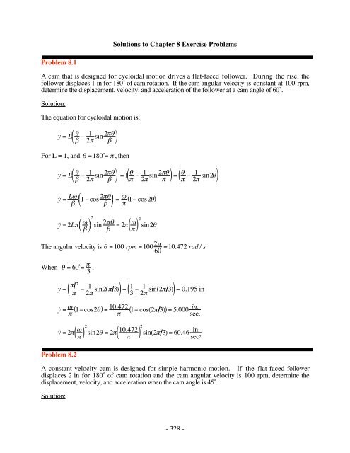
Problem 8.1<br />
Solutions to Chapter 8 Exercise Problems<br />
A cam that is designed for cycloidal motion drives a flat-faced follower. During the rise, the<br />
follower displaces 1 in for 180˚ of cam rotation. If the cam angular velocity is constant at 100 rpm,<br />
determine the displacement, velocity, and acceleration of the follower at a cam angle of 60˚.<br />
Solution:<br />
The equation for cycloidal motion is:<br />
y = L <br />
<br />
1<br />
sin<br />
2<br />
<br />
2 <br />
For L = 1, and =180˚= , then<br />
y = L <br />
<br />
1<br />
sin<br />
2<br />
=1<br />
2 <br />
1 sin<br />
2<br />
( 2 )= 1 2 sin2<br />
( )<br />
y ˙ = L <br />
˙ y ˙ = 2L <br />
<br />
<br />
<br />
<br />
<br />
1 cos<br />
2<br />
=<br />
<br />
( 1 cos2)<br />
<br />
2<br />
<br />
sin 2<br />
= 2 ( ) 2<br />
sin2<br />
The angular velocity is ˙ =100 rpm =100 2<br />
=10.472 rad / s<br />
60<br />
When = 60˚= 3 ,<br />
3<br />
y = <br />
1 ( sin2( 3)<br />
2 ) = 1 <br />
1 ( sin(2 3)<br />
3 2 )= 0.195 in<br />
y ˙ = 1cos2 ( )= 10.472 ( 1 cos(2 3) )= 5.000<br />
<br />
in.<br />
sec.<br />
˙ y ˙ = 2 ( ) 2<br />
Problem 8.2<br />
sin2 = 2 10.472 ( ) 2<br />
sin(2 3) = 60.46 in.<br />
sec2<br />
A constant-velocity cam is designed for simple harmonic motion. If the flat-faced follower<br />
displaces 2 in for 180˚ of cam rotation and the cam angular velocity is 100 rpm, determine the<br />
displacement, velocity, and acceleration when the cam angle is 45˚.<br />
Solution:<br />
- 328 -
The equation for simple harmonic motion is:<br />
y = L 2 1 cos <br />
<br />
<br />
<br />
<br />
For L = 2, and =180˚= , then<br />
y = L 2 1 cos <br />
<br />
<br />
=<br />
<br />
2 1 cos<br />
2( )= ( 1 cos)<br />
y ˙ = dy<br />
dt = d ( 1 cos)=<br />
dt ˙ sin<br />
˙ y ˙ = d2y<br />
dt2 = d dt ˙ ( sin)=<br />
˙ 2cos<br />
The angular velocity is ˙ =100 rpm =100 2<br />
=10.472 rad / s<br />
60<br />
When = 45˚,<br />
y = ( 1 cos)=<br />
( 1 cos45˚)=10.707<br />
= 0.292 in ,<br />
y ˙ = ˙ sin =10.472 sin45˚=10.472 (0.707) = 7.405 in s<br />
˙ y ˙ = ˙ 2 cos =10.4722 (0.707) = 77.531 in<br />
s2<br />
Problem 8.3<br />
A cam drives a radial, knife-edged follower through a 1.5-in rise in 180˚ of cycloidal motion. Give<br />
the displacement at 60˚ and 100˚. If this cam is rotating at 200 rpm, what are the velocity (ds/dt) and<br />
the acceleration (d 2 s/dt 2 ) at = 60˚?<br />
Solution:<br />
The equation for cycloidal motion is:<br />
y = L <br />
<br />
1<br />
sin<br />
2<br />
<br />
2 <br />
For L = 1.5, and =180˚= , then<br />
y = L <br />
<br />
1<br />
sin<br />
2<br />
=1.5<br />
2 <br />
<br />
1<br />
sin<br />
2<br />
( 2 )=1.5 1 2 sin2<br />
( )<br />
y ˙ = L <br />
<br />
1 cos<br />
2<br />
=<br />
<br />
1.5 ( 1cos2 )<br />
<br />
- 329 -
2<br />
<br />
˙ y ˙ = 2L <br />
<br />
<br />
<br />
<br />
sin 2<br />
= 2(1.5) ( ) 2<br />
sin2 = 3 ( ) 2<br />
sin2<br />
The angular velocity is ˙ = 200 rpm = 200 2<br />
= 20.944 rad / s<br />
60<br />
When = 60˚= 3 ,<br />
y =1.5 <br />
1<br />
2 sin2<br />
3<br />
( )=1.5<br />
1 2 sin 2 ( 3 ) = 0.293 in<br />
y ˙ = 1.5 ( 1 cos2)=<br />
1.5(20.944)<br />
1cos<br />
<br />
2 ( 3 )=15.00 in s<br />
˙ y ˙ = 3 ( ) 2<br />
=362.76<br />
in<br />
s2<br />
When =100˚= 100<br />
180 = 5 9 ,<br />
sin2 = 3 20.944 ( ) 2<br />
sin 2 3<br />
( )<br />
y =1.5 <br />
1<br />
2 sin2<br />
5 9<br />
( )=1.5<br />
1 2 sin10 = 0.915 in<br />
9<br />
Problem 8.4<br />
Draw the displacement schedule for a follower that rises through a total displacement of 1.5 inches<br />
with constant acceleration for 1/4th revolution, constant velocity for 1/8th revolution, and constant<br />
deceleration for 1/4th revolution of the cam. The cam then dwells for 1/8th revolution, and returns<br />
with simple harmonic motion in 1/4th revolution of the cam.<br />
Solution:<br />
The displacement profile can be easily computed using the equations in Chapter 8 using Matlab.<br />
The curves are matched at the endpoints of each segment. The profile equations are:<br />
For 0 <br />
2<br />
y1 = a0 + a1 + a2 2<br />
The boundary conditions at = 0 are y1 = 0 and y'1 = 0 . Therefore,<br />
a0 = a1 = 0<br />
So,<br />
and<br />
y1 = a2 2<br />
y'1 = 2a2<br />
where a2 is yet to be determined.<br />
- 330 -
For 3<br />
<br />
2 4<br />
y2 = b0 + b1<br />
( ) 2<br />
The boundary conditions at = <br />
2 are y1 = a2 <br />
2<br />
and<br />
Also<br />
or<br />
b0 + b1 <br />
2<br />
( ) 2<br />
= a2 <br />
2<br />
0 = a2 ( 2 ) 2<br />
+ b0 + b1 <br />
2<br />
y'2 = b1 = a2<br />
0 = a2 b1<br />
For 3 5<br />
<br />
4 4<br />
y3 = c0 + c1 + c2 2<br />
y'3 = c1 + 2c2<br />
y"3 = 2c2<br />
- 331 -<br />
and y'1 = 2a2 <br />
2 = a2 . Then<br />
The boundary conditions at = 3<br />
4 are y2 = a2 <br />
4 + ( ) = a2 3<br />
+<br />
4 4<br />
Also, at = 5<br />
4 , y3 =1.5 and y'3 = 0 . Then, matching the conditions,<br />
2<br />
y3 = a2<br />
2 = c0 +c1 3<br />
4<br />
y'3 = c1 + 2c2 3<br />
= a2<br />
4<br />
1.5 = c0 + c1 5 5<br />
+c2<br />
4 4<br />
( ) 2<br />
3<br />
+ c2( 4 ) 2<br />
y'3 = c1 + 2c2 5<br />
4 = 0<br />
The boundary condition equations can be written as:<br />
( )<br />
= a2 2<br />
2 and y'2 = a2 .
( ) 2<br />
0 = a2 <br />
2<br />
0 = a2 b1<br />
2<br />
0 a2<br />
+ b0 + b1 <br />
2<br />
2 + c0 +c1 3<br />
4<br />
0 = a2 + c1 + 2c2 3<br />
4<br />
1.5 = c0 + c1 5<br />
4<br />
+c2 5<br />
4<br />
( ) 2<br />
+ c2 3<br />
4<br />
( ) 2<br />
0 = c1 + 2c2 5<br />
4<br />
In matrix form,<br />
<br />
0 <br />
0 <br />
<br />
0 <br />
0 =<br />
<br />
0 <br />
<br />
1.5<br />
<br />
( 2)<br />
2<br />
1 <br />
<br />
2<br />
<br />
2<br />
0<br />
0<br />
0<br />
2<br />
1 0<br />
0 1<br />
0<br />
0<br />
0<br />
0<br />
3<br />
<br />
0<br />
0<br />
0<br />
0<br />
0<br />
0 0<br />
0 0<br />
0 1<br />
4<br />
1<br />
1<br />
3<br />
4<br />
3<br />
2<br />
5<br />
2<br />
5<br />
<br />
<br />
<br />
<br />
<br />
<br />
<br />
<br />
<br />
<br />
<br />
<br />
<br />
4<br />
5<br />
4<br />
( ) 2<br />
( ) 2<br />
Solving for the constraints using Matlab,<br />
<br />
<br />
<br />
<br />
<br />
<br />
<br />
<br />
<br />
a2<br />
b0<br />
b1<br />
c0<br />
c1<br />
c2<br />
0.2026 <br />
-0.5000<br />
<br />
0.6366 <br />
= -1.6250<br />
<br />
1.5915 <br />
<br />
<br />
<br />
-0.2026<br />
<br />
<br />
<br />
<br />
<br />
<br />
<br />
<br />
<br />
<br />
<br />
<br />
<br />
<br />
<br />
The equations are then given in the following:<br />
For 0 <br />
2<br />
y1 = a2 2 = 0.2026 2<br />
For 3<br />
<br />
2 4<br />
y2 = b0 + b1 = - 0.5000 + 0.6366<br />
a2<br />
b0<br />
b1<br />
c0<br />
c1<br />
c2<br />
<br />
<br />
<br />
<br />
<br />
<br />
<br />
<br />
<br />
- 332 -
For 3<br />
4<br />
For 5<br />
4<br />
5<br />
4<br />
y3 = c0 + c1 + c2 2 = -1.6250 +1.5915 0.2026 2<br />
3<br />
2<br />
y4 =1.5<br />
For the return, 3<br />
2 2 , and<br />
y5 = L<br />
2<br />
3<br />
1 +cos = ( 1+ cos2)<br />
4<br />
The displacement diagram is plotted in the following:<br />
Normalized Follower Displacement, Velocity, and Acceleration<br />
1<br />
0.8<br />
0.6<br />
0.4<br />
0.2<br />
0<br />
-0.2<br />
-0.4<br />
-0.6<br />
-0.8<br />
-1<br />
Position, max value is: 1.5<br />
Velocity, max value is: 1.5 ( )<br />
Acceleration, max value is: 3 ( 2 )<br />
Follower Displacement, Velocity, and Acceleration Diagrams<br />
TextEnd<br />
0 50 100 150 200 250 300 350<br />
Cam Angle<br />
- 333 -
Problem 8.5<br />
Draw the displacement schedule for a follower that rises through a total displacement of 20 mm<br />
with constant acceleration for 1/8th revolution, constant velocity for 1/4th revolution, and constant<br />
deceleration for 1/8th revolution of the cam. The cam then dwells for 1/4th revolution, and returns<br />
with simple harmonic motion in 1/4th revolution of the cam.<br />
Solution:<br />
The displacement profile can be easily computed using the equations in Chapter 8 using Matlab.<br />
The curves are matched at the endpoints of each segment. The profile equations are:<br />
For 0 <br />
4<br />
y1 = a0 + a1 + a2 2<br />
The boundary conditions at = 0 are y1 = 0 and y'1 = 0 . Therefore,<br />
a0 = a1 = 0<br />
So,<br />
and<br />
y1 = a2 2<br />
y'1 = 2a2<br />
where a2 is yet to be determined.<br />
For 3<br />
<br />
4 8<br />
y2 = b0 + b1<br />
( ) 2<br />
The bounary conditions at = <br />
4 are y1 = a2 <br />
4<br />
and<br />
Also<br />
or<br />
b0 + b1 <br />
4<br />
( ) 2<br />
= a2 <br />
4<br />
0 = a2 ( 4 ) 2<br />
+ b0 + b1 <br />
4<br />
y'2 = b1 = a2 <br />
2<br />
0 = a2 <br />
b1<br />
2<br />
For 3<br />
<br />
8<br />
- 334 -<br />
and y'1 = 2a2 <br />
4<br />
<br />
= a2 . Then,<br />
2
y3 = c0 + c1 + c2 2<br />
y'3 = c1 + 2c2<br />
y"3 = 2c2<br />
The boundary conditions at = 3<br />
8 are y2 = b0 + b1 3<br />
8 and y'2 = b1. Also, at = , y3 = 20, and<br />
y'3 = 0 . Then matching the conditions,<br />
( ) 2<br />
y3 = b0 +b1 3<br />
8 = c0 + c1 3 3<br />
+ c2<br />
8 8<br />
y'3 = c1 + 2c2 3<br />
8 = b1<br />
20 = c0 +c1 + c2 2<br />
y'3 = c1 + 2c2 = 0<br />
The boundary condition equations can be written as:<br />
( ) 2<br />
0 = a2 <br />
4<br />
0 = a2 <br />
b1<br />
2<br />
+ b0 + b1 <br />
4<br />
0 b0 b1 3<br />
8 +c0 + c1 3<br />
8<br />
0 = b1 +c1 +c2 3<br />
4<br />
20 = c0 +c1 + c2 2<br />
0 = c1 + 2c2<br />
In matrix form,<br />
( ) 2<br />
3<br />
+c2 ( 8 ) 2<br />
<br />
0 <br />
0 <br />
<br />
0 <br />
0 =<br />
<br />
0 <br />
<br />
20<br />
<br />
<br />
1 0 0 0<br />
4 4<br />
<br />
0 1 0 0 0<br />
2<br />
0 1 3<br />
1<br />
8<br />
3 3<br />
8 ( 8 ) 2<br />
3<br />
0 0 1 0 1<br />
4<br />
0 0 0 0 1 2<br />
0 0 0 1 2 <br />
<br />
<br />
<br />
<br />
<br />
<br />
<br />
<br />
<br />
<br />
<br />
<br />
<br />
<br />
<br />
<br />
<br />
<br />
<br />
<br />
<br />
<br />
<br />
<br />
Solving for the constraints using Matlab,<br />
a2<br />
b0<br />
b1<br />
c0<br />
c1<br />
c2<br />
<br />
<br />
<br />
<br />
<br />
<br />
<br />
<br />
<br />
- 335 -
a2<br />
b0<br />
b1<br />
c0<br />
c1<br />
c2<br />
7.2051 <br />
-4.4444<br />
<br />
11.3177<br />
= -8.4444<br />
<br />
18.1083<br />
<br />
<br />
<br />
-2.8820<br />
<br />
The equations are then given in the following:<br />
For 0 <br />
4<br />
y1 = a2 2 = 7.2051 2<br />
For 3<br />
<br />
4 8<br />
For 3<br />
8<br />
y2 = b0 + b1 = - 4.4444 +11.3177<br />
<br />
y3 = c0 + c1 + c2 2 = -8.4444 +18.1083 -2.8820 2<br />
For 3<br />
2<br />
y4 = 20 mm<br />
For the return, 3<br />
2 2 , and<br />
y5 = L<br />
2<br />
<br />
1 +cos<br />
<br />
=10( 1+cos 2 )<br />
The displacement diagram is plotted in the following:<br />
- 336 -
Normalized Follower Displacement, Velocity, and Acceleration<br />
1<br />
0.8<br />
0.6<br />
0.4<br />
0.2<br />
0<br />
-0.2<br />
-0.4<br />
-0.6<br />
-0.8<br />
-1<br />
Problem 8.6<br />
Position, max value is: 20<br />
Velocity, max value is: 20 ( )<br />
Acceleration, max value is: 40 ( 2 )<br />
Follower Displacement, Velocity, and Acceleration Diagrams<br />
TextEnd<br />
0 50 100 150 200 250 300 350<br />
Cam Angle<br />
Draw the displacement schedule for a follower that rises through a total displacement of 30 mm<br />
with constant acceleration for 90˚ of rotation and constant deceleration for 45˚ of cam rotation. The<br />
follower returns 15 mm with simple harmonic motion in 90˚ of cam rotation and dwells for 45˚ of<br />
cam rotation. It then returns the remaining 15 mm with simple harmonic motion during the<br />
remaining 90˚ of cam rotation.<br />
Solution:<br />
The displacement profile can be easily computed using the equations in Chapter 8 using Matlab.<br />
The curves are matched at the endpoints of each segment. The profile equations are:<br />
For 0 <br />
2<br />
y1 = a0 + a1 + a2 2<br />
The boundary conditions at = 0 are y1 = 0 and y'1 = 0 . Therefore,<br />
a0 = a1 = 0<br />
So,<br />
and<br />
y1 = a2 2<br />
y'1 = 2a2<br />
- 337 -
where a2 is yet to be determined.<br />
For 3<br />
<br />
2 4<br />
y2 = b0 + b1 + b2 2<br />
( ) 2<br />
The boundary conditions at = <br />
2 and y1 = a2 <br />
2<br />
b0 + b1 <br />
+b2<br />
2 ( 2)<br />
2<br />
= a2 ( 2 ) 2<br />
and<br />
Also<br />
0 = a2 ( 2 ) 2<br />
+ b0 + b1 <br />
2<br />
y'2 = b1 + b2 = a2<br />
( ) 2<br />
+ b2 <br />
2<br />
- 338 -<br />
and y'1 = 2a2 <br />
2 = a2 . Then,<br />
or<br />
0 = a2 + b1 +b2<br />
The boundary conditions at = 3<br />
4 are y2 = 30 and y'2 = 0 . Then,<br />
and<br />
b0 + b1 3<br />
4<br />
( ) 2<br />
+ b2 3<br />
4<br />
0 = b1 +2b2 3<br />
4<br />
= 30<br />
( )= b1 + b2 3<br />
( )<br />
The four boundary condition equations can be summarized as:<br />
( ) 2<br />
0 = a2 <br />
2<br />
0 = a2 + b1 +b2<br />
30 = b0 + b1 3<br />
4<br />
( )<br />
0 = b1 +b2 3<br />
2<br />
In matrix form,<br />
( ) 2<br />
+ b0 + b1 <br />
2<br />
( ) 2<br />
+b2 3<br />
4<br />
( ) 2<br />
2<br />
( ) 2<br />
+ b2 <br />
2<br />
0<br />
<br />
<br />
0 <br />
=<br />
30<br />
<br />
0 <br />
<br />
<br />
1<br />
<br />
2 2 2<br />
0 1 <br />
0 1 3 3<br />
4 ( 4 ) 2<br />
<br />
<br />
<br />
<br />
<br />
<br />
<br />
<br />
<br />
<br />
<br />
<br />
<br />
0 0 1<br />
3 <br />
<br />
<br />
2 <br />
a2<br />
b0<br />
b1<br />
b2<br />
<br />
<br />
<br />
<br />
<br />
<br />
7.5
Solving for the constraints using Matlab,<br />
<br />
<br />
<br />
<br />
<br />
<br />
a2<br />
b0<br />
b1<br />
b2<br />
8.1057 <br />
-60.0000<br />
= <br />
76.3944 <br />
<br />
<br />
<br />
-16.2114<br />
<br />
The equations are then given in the following:<br />
For 0 <br />
2<br />
y1 = a2 2 = 8.1057 2<br />
For 3<br />
<br />
2 4<br />
y2 = b0 + b1 + b2 2 = -60.0000 + 76.3944 +-16.2114 2<br />
For 3 5<br />
<br />
4 4<br />
= <br />
2<br />
and<br />
y3 = L<br />
<br />
1+ cos<br />
2 <br />
= 15<br />
2<br />
( 1+ cos2)<br />
This equation assumes that the curve is 15 mm high and that the curve falls to zero. However, the<br />
actual curve begins at a height of 30 mm and returns to only 15 mm. Because of this, we need to<br />
add 15 mm to the value for y3. Then,<br />
y3 =15+ 7.5( 1+ cos2 )<br />
For 5 6<br />
<br />
4 4<br />
y4 =15<br />
For 6<br />
2<br />
4<br />
= <br />
2<br />
and<br />
y5 = L<br />
2<br />
<br />
1 +cos<br />
<br />
= 15<br />
2<br />
( 1 +cos2)<br />
The displacement diagram is plotted in the following:<br />
- 339 -
Normalized Follower Displacement, Velocity, and Acceleration<br />
1<br />
0.8<br />
0.6<br />
0.4<br />
0.2<br />
0<br />
-0.2<br />
-0.4<br />
-0.6<br />
-0.8<br />
-1<br />
Problem 8.7<br />
Position, max value is: 30<br />
Velocity, max value is: 25.4648 ( )<br />
Acceleration, max value is: 32.4228 ( 2 )<br />
Follower Displacement, Velocity, and Acceleration Diagrams<br />
TextEnd<br />
0 50 100 150 200 250 300 350<br />
Cam Angle<br />
Draw the displacement schedule for a follower that rises through a total displacement of 3 inches<br />
with cycloidal motion in 120 degrees of cam rotation. The follower then dwells for 90˚ and returns<br />
to zero with simple harmonic motion in 90˚ of cam rotation. The follower then dwells for 60˚<br />
before repeating the cycle.<br />
Solution:<br />
The displacement profile can be easily computed using the equations in Chapter 8 using Matlab.<br />
The curves are matched at the endpoints of each segment. The profile equations are:<br />
For 0 2<br />
3<br />
and<br />
= 2<br />
3<br />
y1 = L <br />
( )<br />
1 2 3 1<br />
sin = 3 <br />
2 2 2 sin3<br />
- 340 -
( )<br />
y'1 = L 1 1 2 3 3<br />
cos = 3 cos 3<br />
2 2<br />
y"1 = L 2 <br />
2 sin2<br />
<br />
<br />
<br />
= 3 9<br />
2 sin3 ( )<br />
For 2 7<br />
<br />
3 6<br />
y2 = 3<br />
For the return, 7<br />
6<br />
and<br />
= <br />
2<br />
5<br />
3 _<br />
y3 = L<br />
<br />
1+ cos<br />
2 <br />
For the remainder of the cycle,<br />
and<br />
5<br />
3<br />
y4 = 0<br />
2<br />
=1.5( 1+ cos2)<br />
The displacement diagram is plotted in the following:<br />
- 341 -
Normalized Follower Displacement, Velocity, and Acceleration<br />
1<br />
0.8<br />
0.6<br />
0.4<br />
0.2<br />
0<br />
-0.2<br />
-0.4<br />
-0.6<br />
-0.8<br />
-1<br />
Problem 8.8<br />
Position, max value is: 3<br />
Velocity, max value is: 3 ( )<br />
Acceleration, max value is: 6 ( 2 )<br />
Follower Displacement, Velocity, and Acceleration Diagrams<br />
TextEnd<br />
0 50 100 150 200 250 300 350<br />
Cam Angle<br />
A cam returns from a full lift of 1.2 in during its initial 60˚ rotation. The first 0.4 in of the return is<br />
half-cycloidal. This is followed by a half-harmonic return. Determine 1 and 2 so that the motion<br />
has continuous first and second derivatives. Draw a freehand sketch of y', y'', and y''' indicating<br />
any possible mismatch in the third derivative.<br />
Solution:<br />
Follower Travel<br />
1.2 in<br />
0.4 in<br />
- 342 -<br />
Not to Scale<br />
0˚ 60˚<br />
β 1 β 2<br />
The first part of the return is made up of a cycloidal curve and the second part is made up of a<br />
harmonic curve. This is shown schematically in the figure below.
Follower Travel<br />
1.2"<br />
β1 β2<br />
0.4"<br />
The range for the cycloidal curve is given by<br />
0 1 21<br />
Cycloidal Curve<br />
and the range for the harmonic curve is given by<br />
Also,<br />
1 2 2 1 + 2<br />
2 =1 (1 2)<br />
0˚ 60˚<br />
β1<br />
β2<br />
- 343 -<br />
2β<br />
2<br />
2 β1<br />
Harmonic Curve<br />
The general form for the cycloidal equation for a return is given in Section 7.8 as<br />
y = L 1 <br />
+<br />
1<br />
sin<br />
2 <br />
2 <br />
Half of the cycloidal return is 0.4 so return is 0.8. The range for 1 is 21. As<br />
indicated in the figure above, the cycloidal curve is offset from the horizontal axis by 0.4".<br />
Therefore, this much must be added to y. The cycloidal equation for the return is<br />
<br />
y1 = L1 1 1 21 + 1<br />
= 0.8 1.5 1<br />
<br />
2 1<br />
<br />
2 sin 21 21 +0.4 = 0.8 1 1 21 + 1 2 sin 1<br />
1<br />
<br />
<br />
<br />
+ 1 2 sin 1<br />
1<br />
<br />
+0.4<br />
The harmonic curve is given by Eq. (812). Half of the harmonic return is (1.2"-0.4") = 0.8 so that<br />
the whole return is 1.6". The range for 2 is 22 . Therefore, the equation for the harmonic part<br />
of the return is:<br />
y2 = L 2<br />
2 1+ cos <br />
2<br />
= 0.8 1+ cos <br />
2 <br />
<br />
2 2<br />
2 2<br />
We also know that 2 =1 (1 2) and 2 = 3<br />
1<br />
0.4"<br />
(1)<br />
(2)
Eqs. (1) and (2) can be reduced so that the only unknown is 1. To solve for the unknown, we can<br />
equate the slopes at 1 = 1 . For the cycloidal equation,<br />
y'1= 0.8 <br />
<br />
and at 1 = 1<br />
2 1<br />
y'1= 0.8 <br />
<br />
2 1<br />
1 cos 1 1 1 cos 1 1 For the harmonic equation<br />
y'2 = 0.4<br />
sin 2 <br />
<br />
2<br />
2 2<br />
<br />
<br />
<br />
<br />
At 1 = 1, 2 = 2. Therefore,<br />
y'2 = 0.4 <br />
<br />
2<br />
sin 2 22 = 0.8<br />
1<br />
<br />
<br />
= <br />
0.4 <br />
<br />
2<br />
sin 2 22 <br />
<br />
= 0.4<br />
2<br />
Equation Eqs. (3) and (4) give the following equation<br />
or<br />
0.8<br />
1<br />
= 0.4<br />
2<br />
2<br />
=<br />
1 =<br />
<br />
2 /3 1 This equation can be easily solved for 1. The result is: 1 =<br />
- 344 -<br />
2<br />
= 0.4073436 radians.<br />
3( +2)<br />
We can now write y, y', and y" for each part of the curve. For 1 0.4073436<br />
y = 0.8 1.5 1 + 1<br />
<br />
<br />
y' = 0.8 <br />
<br />
2 1<br />
y"= 0.8 <br />
<br />
2 1<br />
1 cos 1 1 22 1 sin 1 1 2 sin 1<br />
1 <br />
<br />
<br />
<br />
and for 0.4073436 /3<br />
y = 0.8 1+cos <br />
2 <br />
<br />
2 2<br />
<br />
<br />
(3)<br />
(4)<br />
(4)
where<br />
y' = 0.4 <br />
<br />
2<br />
y"= 0.2 2<br />
2 2<br />
sin 2<br />
22 <br />
<br />
<br />
<br />
cos 2<br />
22 <br />
<br />
2 =1 (1 2) and 2 = 3<br />
1<br />
The results are plotted in the following<br />
- 345 -
Problem 8.9<br />
Assume that s is the cam-follower displacement and is the cam rotation. The rise is 1.0 cm after<br />
1.0 radian of rotation, and the rise begins and ends at a dwell. The displacement equation for the<br />
follower during the rise period is<br />
n<br />
i<br />
<br />
s = h Ci <br />
<br />
<br />
<br />
<br />
i =0<br />
If the position, velocity, and acceleration are continuous at = 0, and the position and velocity are<br />
continuous at = 1.0 rad, determine the value of n required in the equation, and find the coefficients<br />
Ci if ˙ = 2 rad/s. Note: Use the minimum possible number of terms.<br />
Solution:<br />
Dwell<br />
1.0<br />
S<br />
Β<br />
Α 1.0<br />
- 346 -<br />
Dwell<br />
First determine the number of terms required. There are a total of five conditions to match;<br />
therefore, the number of terms is 5 making n = 4.<br />
The conditions to match are:<br />
At = 0 , s = ds<br />
=<br />
d2s<br />
= 0<br />
d d2<br />
At = , s = h = 1.0<br />
ds<br />
= 0<br />
d<br />
Now,<br />
s = Ci <br />
<br />
<br />
<br />
n i<br />
= C0 +C1<br />
<br />
<br />
<br />
<br />
<br />
+ C2<br />
<br />
<br />
<br />
<br />
<br />
2<br />
+C3<br />
<br />
<br />
<br />
<br />
<br />
3<br />
+ C4<br />
<br />
<br />
<br />
<br />
<br />
4<br />
<br />
<br />
and<br />
i=0<br />
ds<br />
d = C1 + 2C2 <br />
<br />
<br />
<br />
+<br />
<br />
3C3 <br />
<br />
<br />
<br />
<br />
<br />
d2s<br />
d 2 = 2C 2<br />
2 + 6C3 2<br />
2<br />
<br />
<br />
<br />
<br />
+<br />
<br />
12C4 <br />
<br />
2 <br />
<br />
<br />
<br />
+ 4C 4<br />
<br />
2<br />
<br />
<br />
<br />
<br />
<br />
<br />
3<br />
θ, rad
Applying the conditions at = 0 ,<br />
s = C0 = 0<br />
ds<br />
d = C 1<br />
C1 = 0<br />
d2s<br />
d 2 = 2C 2<br />
2 = 0 C2 = 0<br />
Applying the conditions at = ,<br />
or<br />
s = C3 <br />
<br />
3<br />
<br />
<br />
ds<br />
d = 3C3 <br />
<br />
<br />
<br />
<br />
<br />
<br />
3C3 + 4C4 = 0<br />
4<br />
<br />
+C4 <br />
<br />
<br />
<br />
<br />
2<br />
+ 4C 4<br />
<br />
Solving for the constants,<br />
and<br />
C3 = 4<br />
C4 = 3<br />
Therefore,<br />
s = 4 <br />
<br />
<br />
<br />
<br />
Problem 8.10<br />
3<br />
<br />
4<br />
<br />
3 <br />
<br />
<br />
<br />
<br />
= C3 + C4 =1<br />
<br />
<br />
<br />
<br />
<br />
<br />
<br />
3<br />
= 3C3 + 4C4 = 0<br />
<br />
Resolve Problem 8.9 if = 0.8 rad and ˙<br />
= 200 rad/s.<br />
Solution:<br />
First determine the number of terms required. There are a total of five conditions to match;<br />
therefore, the number of terms is 5 making n = 4.<br />
The conditions to match are:<br />
At = 0 , s = ds<br />
=<br />
d2s<br />
= 0<br />
d d2<br />
At = , s = h = 1.0<br />
- 347 -
Now,<br />
and<br />
ds<br />
= 0<br />
d<br />
s = Ci <br />
n i<br />
<br />
= C0 +C1<br />
<br />
i= 0<br />
<br />
<br />
ds C1 2C2 <br />
= +<br />
d <br />
d2s 2C2 6C3<br />
d 2 =<br />
2 +<br />
2<br />
+ 3C3<br />
<br />
<br />
+C2<br />
<br />
<br />
<br />
2<br />
<br />
<br />
+12C4<br />
<br />
<br />
2<br />
Applying the conditions at = 0 ,<br />
s = C0 = 0<br />
ds C1<br />
=<br />
d C1 = 0<br />
d2s 2C2<br />
d 2 =<br />
2 = 0 C2 = 0<br />
Applying the conditions at = ,<br />
or<br />
s = C3 <br />
3<br />
<br />
+ C4 <br />
4<br />
<br />
<br />
ds 3C3<br />
=<br />
d <br />
<br />
<br />
3C3 + 4C4 = 0<br />
2<br />
<br />
+ 4C4<br />
<br />
Solving for the constants,<br />
and<br />
C3 = 4<br />
C4 = 3<br />
Therefore,<br />
s = 4 <br />
<br />
3<br />
3 <br />
<br />
4<br />
+ 4C4<br />
<br />
2<br />
= C3 +C4 =1<br />
<br />
<br />
3<br />
= 3C3<br />
<br />
2<br />
+C3 <br />
<br />
<br />
<br />
+ 4C4<br />
<br />
3<br />
= 0<br />
- 348 -<br />
3<br />
+C4 <br />
<br />
Notice that this solution is EXACTLY the same as that for 8.9. The results are independent of both<br />
and ˙ . This is one of the reasons for normalizing the problem with respect to .<br />
4
Problem 8.11<br />
For the cam displacement schedule given, h is the rise, is the angle through which the rise takes<br />
place, and s is the displacement at any given angle . The displacement equation for the follower<br />
during the rise period is<br />
5<br />
i<br />
<br />
s = h ai <br />
<br />
<br />
<br />
<br />
i =0<br />
Determine the required values for a 0 ... a 5 such that the displacement, velocity, and acceleration<br />
functions are continuous at the end points of the rise portion.<br />
Solution:<br />
Dwell<br />
h<br />
Α<br />
S<br />
Β<br />
β<br />
- 349 -<br />
Dwell<br />
θ, rad<br />
There are a total of six conditions to match; therefore, the number of terms is 6 making n = 5.<br />
The conditions to match are:<br />
At = 0 , s = ds<br />
=<br />
d2s<br />
= 0<br />
d d2<br />
At = , s = h<br />
and<br />
ds<br />
=<br />
d2s<br />
= 0<br />
d d 2<br />
Now,<br />
s = h Ci <br />
<br />
<br />
<br />
n i<br />
= hC0 +C1<br />
<br />
<br />
<br />
<br />
<br />
+ C2<br />
<br />
<br />
<br />
<br />
<br />
2<br />
+C3<br />
<br />
<br />
<br />
<br />
<br />
3<br />
+ C4<br />
<br />
<br />
<br />
<br />
<br />
4<br />
+ C5<br />
<br />
<br />
<br />
<br />
<br />
<br />
5<br />
<br />
<br />
<br />
<br />
<br />
<br />
and<br />
i=0<br />
ds<br />
d = h C1 + 2C2 <br />
<br />
<br />
<br />
+<br />
<br />
3C3 <br />
<br />
<br />
<br />
<br />
<br />
<br />
<br />
<br />
d2s<br />
d 2 = h 2C <br />
2<br />
<br />
<br />
2 + 6C3 2<br />
2<br />
<br />
<br />
<br />
<br />
+<br />
<br />
12C4 <br />
<br />
2 <br />
<br />
<br />
<br />
+ 4C 4<br />
<br />
2<br />
<br />
<br />
<br />
<br />
<br />
<br />
+ 20C 5<br />
2<br />
3<br />
+ 5C5 <br />
<br />
<br />
<br />
4<br />
<br />
<br />
<br />
<br />
<br />
<br />
<br />
<br />
3
Applying the conditions at = 0 ,<br />
s = C0 = 0<br />
ds<br />
d = h C 1<br />
C1 = 0<br />
d2s<br />
d 2 = h 2C 2<br />
2 = 0 C2 = 0<br />
Applying the conditions at = ,<br />
or<br />
or<br />
or<br />
s = hC3 <br />
<br />
<br />
<br />
<br />
<br />
3<br />
<br />
C3 + C4 +C5 =1<br />
ds<br />
d = h 3C3 <br />
<br />
<br />
<br />
<br />
<br />
<br />
+C4 <br />
<br />
<br />
<br />
<br />
3C3 + 4C4 +5C5 = 0<br />
2<br />
+ 4C 4<br />
<br />
4<br />
+ C5 <br />
d2s<br />
d 2 = h 6C3 <br />
<br />
<br />
2 <br />
<br />
+<br />
<br />
12C4 <br />
<br />
<br />
2 <br />
<br />
<br />
<br />
<br />
<br />
<br />
6C3 +12C4 + 20C5 = 0<br />
Solving for the constants,<br />
C3 =10; C4 = 15; C5 = 6<br />
Therefore,<br />
s = h 10 <br />
<br />
<br />
<br />
3<br />
15<br />
<br />
<br />
<br />
<br />
<br />
4<br />
+ 6<br />
<br />
<br />
<br />
<br />
<br />
<br />
5<br />
<br />
<br />
<br />
<br />
<br />
<br />
Problem 8.12<br />
<br />
<br />
<br />
5<br />
<br />
<br />
= hC3 [ + C4 + C5]=h<br />
<br />
<br />
<br />
<br />
<br />
<br />
3<br />
<br />
<br />
= h<br />
<br />
3C3 + 4C4 + 5C <br />
5<br />
<br />
<br />
= 0<br />
2<br />
+ 20C 5<br />
2<br />
<br />
<br />
<br />
<br />
<br />
3<br />
<br />
<br />
= h<br />
<br />
6C 3<br />
<br />
Resolve Problem 8.11 if h = 20 mm and = 120˚.<br />
Solution:<br />
- 350 -<br />
2 +12C4 2 + 20C5 2<br />
<br />
<br />
= 0<br />
There are a total of six conditions to match; therefore, the number of terms is 6 making n = 5.<br />
The conditions to match are:<br />
At = 0 , s = ds<br />
d = d2s d2 = 0
At = , s = h<br />
and<br />
ds<br />
d = d2s d 2 = 0<br />
Now,<br />
s = h Ci <br />
n<br />
<br />
<br />
and<br />
i<br />
= hC0 + C1<br />
i= 0<br />
<br />
2<br />
<br />
+ C2 + C3<br />
<br />
<br />
<br />
<br />
3<br />
<br />
<br />
<br />
<br />
ds C1<br />
= h<br />
d<br />
<br />
<br />
<br />
+ 2C2<br />
<br />
<br />
<br />
<br />
d2s 2C2 6C3<br />
d 2 = h<br />
2 +<br />
2<br />
<br />
<br />
<br />
+ 3C3<br />
<br />
<br />
<br />
Applying the conditions at = 0 ,<br />
s = C0 = 0<br />
ds C1<br />
= h<br />
d C1 = 0<br />
d2s 2C2<br />
d 2 = h<br />
2 = 0 C2 = 0<br />
Applying the conditions at = _<br />
or<br />
or<br />
or<br />
s = hC3 <br />
<br />
<br />
3<br />
C3 +C4 +C5 = 1<br />
ds 3C3<br />
= h<br />
d<br />
<br />
<br />
<br />
<br />
<br />
+C4 <br />
<br />
3C3 + 4C4 +5C5 = 0<br />
d2s 6C3<br />
d 2 = h<br />
2<br />
<br />
<br />
<br />
2<br />
+ 4C4<br />
<br />
<br />
<br />
+ 12C4<br />
2<br />
2<br />
+ 4C4<br />
<br />
<br />
<br />
4<br />
+ C5 <br />
5<br />
<br />
3<br />
<br />
<br />
+12C4<br />
<br />
<br />
6C3 +12C4 + 20C5 = 0<br />
Solving for the constants,<br />
2<br />
<br />
2<br />
<br />
3C3<br />
<br />
= h<br />
<br />
<br />
2<br />
+ 20C5<br />
2<br />
<br />
<br />
+ 20C5<br />
2<br />
3<br />
- 351 -<br />
+ 5C5<br />
<br />
3<br />
<br />
<br />
<br />
<br />
+C4 <br />
<br />
<br />
<br />
<br />
<br />
= hC3 [ +C4 + C5 ]= h<br />
+ 4C4<br />
<br />
<br />
<br />
3<br />
+ 5C5<br />
<br />
6C3<br />
= h<br />
<br />
<br />
4<br />
<br />
<br />
= 0<br />
<br />
<br />
<br />
2 +12C4<br />
4<br />
+ C5 <br />
5<br />
<br />
<br />
<br />
20C5<br />
2 +<br />
2<br />
<br />
<br />
= 0
C3 =10; C4 = 15; C5 = 6<br />
Therefore,<br />
s = h 10 <br />
<br />
<br />
3<br />
15 <br />
<br />
If h=20 mm and = 120˚, then,<br />
( ) 3<br />
s = 20 10 <br />
<br />
120<br />
4<br />
15 ( 120)<br />
4<br />
+6 <br />
<br />
5<br />
<br />
<br />
<br />
( ) 5<br />
+6 <br />
120<br />
<br />
<br />
<br />
Here, is assumed to be given in degrees. Note that the values for h and do not enter the<br />
problem until the last step.<br />
Problem 8.13<br />
Resolve Problem 8.11 if h = 2 in and = 90˚.<br />
Solution:<br />
There are a total of six conditions to match; therefore, the number of terms is 6 making n = 5.<br />
The conditions to match are:<br />
At = 0 , s = ds<br />
d = d2s d2 = 0<br />
At = , s = h<br />
and<br />
ds<br />
d = d2s d 2 = 0<br />
Now,<br />
s = h Ci <br />
n<br />
<br />
<br />
and<br />
i<br />
= hC0 + C1<br />
i= 0<br />
<br />
2<br />
<br />
+ C2 + C3<br />
<br />
<br />
<br />
<br />
3<br />
<br />
<br />
<br />
<br />
ds C1<br />
= h<br />
d<br />
<br />
<br />
<br />
+ 2C2<br />
<br />
<br />
<br />
<br />
d2s 2C2 6C3<br />
d 2 = h<br />
2 +<br />
2<br />
<br />
<br />
<br />
+ 3C3<br />
<br />
<br />
<br />
Applying the conditions at = 0 ,<br />
s = C0 = 0<br />
<br />
<br />
+ 12C4<br />
2<br />
2<br />
+ 4C4<br />
<br />
<br />
<br />
2<br />
<br />
<br />
+ 20C5<br />
2<br />
3<br />
- 352 -<br />
+ 5C5<br />
<br />
3<br />
<br />
<br />
<br />
<br />
+C4 <br />
<br />
<br />
<br />
4<br />
<br />
<br />
<br />
4<br />
+ C5 <br />
5
ds C1<br />
= h<br />
d C1 = 0<br />
d2s 2C2<br />
d 2 = h<br />
2 = 0 C2 = 0<br />
Applying the conditions at = _<br />
or<br />
or<br />
or<br />
s = hC3 <br />
<br />
<br />
3<br />
C3 +C4 +C5 = 1<br />
ds 3C3<br />
= h<br />
d<br />
<br />
<br />
<br />
<br />
<br />
+C4 <br />
<br />
3C3 + 4C4 +5C5 = 0<br />
d2s 6C3<br />
d 2 = h<br />
2<br />
<br />
<br />
<br />
2<br />
+ 4C4<br />
<br />
4<br />
+ C5 <br />
5<br />
<br />
3<br />
<br />
<br />
+12C4<br />
<br />
<br />
6C3 +12C4 + 20C5 = 0<br />
Solving for the constants,<br />
2<br />
C3 =10; C4 = 15; C5 = 6<br />
Therefore,<br />
s = h 10 <br />
<br />
<br />
3<br />
15 <br />
<br />
If h=2 in and = 90˚, then,<br />
( ) 3<br />
s = 210 <br />
<br />
90<br />
4<br />
15 ( 90)<br />
4<br />
<br />
<br />
3C3<br />
<br />
= h<br />
<br />
<br />
2<br />
+6 <br />
<br />
+ 20C5<br />
2<br />
5<br />
( ) 5<br />
+6 <br />
90<br />
<br />
<br />
<br />
<br />
<br />
<br />
<br />
<br />
= hC3 [ +C4 + C5 ]= h<br />
+ 4C4<br />
<br />
<br />
<br />
3<br />
- 353 -<br />
+ 5C5<br />
<br />
6C3<br />
= h<br />
<br />
<br />
<br />
<br />
= 0<br />
2 +12C4<br />
20C5<br />
2 +<br />
2<br />
<br />
<br />
= 0<br />
Here, is assumed to be given in degrees. Note that the values for h and do not enter the<br />
problem until the last step.
Problem 8.14<br />
Assume that s is the cam-follower displacement and is the cam rotation. The rise is h after <br />
degrees of rotation, and the rise begins at a dwell and ends with a constant velocity segment. The<br />
displacement equation for the follower during the rise period is<br />
n<br />
i<br />
<br />
s = h Ci <br />
<br />
<br />
<br />
<br />
i =0<br />
If the position, velocity, and acceleration are continuous at = 0 and the position and velocity are<br />
continuous at = , determine the n required in the equation, and find the coefficients C i that will<br />
satisfy the requirements if s = h = 1.0.<br />
Solution:<br />
Dwell<br />
S<br />
β<br />
First determine the number of terms required. There are a total of five conditions to match;<br />
therefore, the number of terms is 5 making n = 4.<br />
The conditions to match are:<br />
At = 0 , s = ds<br />
=<br />
d2s<br />
= 0<br />
d d2<br />
At = , s = h = 1.0<br />
ds<br />
= tan45˚=1.0<br />
d<br />
Now,<br />
s = Ci <br />
<br />
<br />
<br />
n i<br />
= C0 +C1<br />
<br />
<br />
<br />
<br />
<br />
+ C2<br />
<br />
<br />
<br />
<br />
<br />
2<br />
+C3<br />
<br />
<br />
<br />
<br />
<br />
3<br />
+ C4<br />
<br />
<br />
<br />
<br />
<br />
4<br />
<br />
<br />
i=0<br />
- 354 -<br />
h<br />
45˚<br />
θ
and<br />
ds<br />
d = C1 + 2C2 <br />
<br />
<br />
<br />
+<br />
<br />
3C3 <br />
<br />
<br />
<br />
<br />
<br />
d2s<br />
d 2 = 2C 2<br />
2 + 6C3 2<br />
2<br />
<br />
<br />
<br />
<br />
+<br />
<br />
12C4 <br />
<br />
2 <br />
<br />
<br />
<br />
Applying the conditions at = 0 ,<br />
s = C0 = 0<br />
ds<br />
d = C 1<br />
C1 = 0<br />
d2s<br />
d 2 = 2C 2<br />
2 = 0 C2 = 0<br />
Applying the conditions at = ,<br />
or<br />
s = C3 <br />
<br />
3<br />
<br />
<br />
ds<br />
d = 3C3 <br />
<br />
<br />
<br />
<br />
<br />
<br />
3C3 + 4C4 = <br />
4<br />
<br />
+C4 <br />
<br />
<br />
<br />
<br />
2<br />
+ 4C 4<br />
<br />
Solving for the constants,<br />
and<br />
C3 = 4 <br />
C4 = 3<br />
Therefore,<br />
s =(4 ) <br />
<br />
<br />
<br />
<br />
Problem 8.15<br />
3<br />
<br />
+ 4C 4<br />
<br />
2<br />
= C3 + C4 =1<br />
<br />
<br />
<br />
<br />
<br />
<br />
<br />
3<br />
+( 3) <br />
<br />
<br />
<br />
<br />
<br />
<br />
<br />
<br />
<br />
<br />
3<br />
= 3C 3<br />
+ 4C 4<br />
=1<br />
4<br />
<br />
A follower moves with simple harmonic motion a distance of 20 mm in 45˚ of cam rotation. The<br />
follower then moves 20 mm more with cycloidal motion to complete its rise. The follower then<br />
dwells and returns 25 mm with cycloidal motion and then moves the remaining 15 mm with<br />
harmonic motion in 45˚. Find the intervals of cam rotation for the cycloidal motions and dwell by<br />
matching velocities and accelerations, then determine the equations for the displacement (S) as a<br />
function of for the entire motion cycle.<br />
Solution:<br />
- 355 -
This is a curve matching problem. To begin the problem, consider the equations for harmonic and<br />
cycloidal motions:<br />
Harmonic:<br />
y = L<br />
2<br />
Cycloidal:<br />
<br />
1cos<br />
<br />
y'= L<br />
2 sin<br />
<br />
<br />
y"= 2L <br />
22 cos<br />
<br />
y = L 1 2 <br />
sin<br />
2 <br />
y'= L 1 1 2<br />
cos<br />
<br />
y"= L 2 2 <br />
2 sin<br />
<br />
<br />
<br />
<br />
For both the harmonic and cycloidal motions, we must determine L and . There are a total of four<br />
curves, so we need to determine four L’s and four ’s The geometry is shown in the following<br />
figure.<br />
Follower Travel<br />
Cycloidal Curve<br />
45˚<br />
2<br />
1<br />
Harmonic Curve<br />
20<br />
20<br />
25<br />
- 356 -<br />
15<br />
Harmonic Curve<br />
Cycloidal Curve<br />
We can treat the rise and return separately, and then determine the dwell to ensure that there is a full<br />
cycle of motion.<br />
3<br />
4<br />
45˚
For the rise section, assume that the harmonic curve is half-harmonic, and the cycloidal curve is half<br />
cycloidal. This will allow us to match the curves at their inflections points and will ensure curvature<br />
continuity. For the harmonic curve,<br />
and<br />
2 = <br />
2<br />
L2 = 40<br />
Therefore, the harmonic curve is<br />
y = L 40<br />
1cos = ( 1 cos2 )= 20( 1 cos2)<br />
2 2<br />
The slope equation is<br />
y'= L<br />
2 sin<br />
<br />
<br />
1<br />
= Lsin2 ( )<br />
Or the cycloidal curve,<br />
L1 = 40<br />
and<br />
y = L1 1 1 21 1 1 21 <br />
sin = 40 sin<br />
2 2 <br />
1<br />
The slope equation is<br />
y'= L1 1 1 21 <br />
cos<br />
1 1 1 <br />
To find 1, equate the slopes at the midpoint, then,<br />
y'= L2 sin2 2 1 1 2 1<br />
2 <br />
= L1 cos<br />
1 1 1 2 <br />
or<br />
or<br />
40( sin2 )= 40 1 1<br />
<br />
1 cos<br />
<br />
<br />
<br />
<br />
sin ( 2)<br />
1<br />
1<br />
1 1<br />
= <br />
1 cos<br />
<br />
<br />
<br />
<br />
Then,<br />
2<br />
1 =1<br />
or<br />
1 = 2<br />
The rise part of the curve is given by,<br />
For < <br />
4<br />
1<br />
1<br />
- 357 -
y = 20( 1 cos2 )<br />
The cycloidal curve starts at<br />
= (2 1)/2 = ( 2<br />
2 )/ 2 = 0.2146<br />
Therefore,<br />
1 = + 0.2146<br />
<br />
< <<br />
1<br />
+<br />
Then for <br />
<br />
4 4 2 <br />
y = 40 1 1 21<br />
[ + 0.2146]<br />
sin = 40 <br />
2 2<br />
1<br />
<br />
sin[ +0.2146]<br />
<br />
<br />
2 <br />
1<br />
1<br />
The angular distance to the dwell is<br />
= 1<br />
+<br />
2<br />
4 2 <br />
= ( +<br />
4 2)=1+<br />
<br />
4<br />
For the return, use the same procedure. The harmonic part of the return is given by<br />
y4 = L4 <br />
1+ cos4<br />
2 <br />
4<br />
Where<br />
L4 = 2(15) = 30<br />
and<br />
4 = <br />
2<br />
Therefore,<br />
y4 =15( 1+ cos24 )<br />
For the cycloidal curve,<br />
y3 = L3 L3 3 1 23<br />
sin<br />
2 <br />
Where<br />
3<br />
3<br />
L3 = 2(25) = 50<br />
To determine 3, equate the slopes for the two curves at their midpoints. Then,<br />
or<br />
y'4 = L4 <br />
sin<br />
24 4<br />
30 sin ( 2)<br />
Solving for 3,<br />
Or<br />
2<br />
3<br />
= 3<br />
5<br />
3<br />
4<br />
2<br />
<br />
= y'3 = L3 1 <br />
<br />
1 1<br />
= 50 <br />
3 cos<br />
<br />
<br />
<br />
<br />
3<br />
1<br />
3<br />
- 358 -<br />
cos 2<br />
3<br />
3<br />
2
3 = 10<br />
3<br />
The cycloidal part of the curve will start at<br />
= 2 ( 3 +4 )/ 2<br />
Therefore, the dwell period will be<br />
1<br />
+<br />
<br />
4 2 < < 2 3 ( +4 )/ 2<br />
And the dwell distance will b,<br />
y = 40<br />
The cycloidal part of the curve occurs when<br />
2 ( 3 +4 )/ 2 < < 2 3 / 2<br />
And<br />
<br />
y3 = L3 L3 3<br />
3<br />
1 23<br />
sin<br />
2 <br />
The curve will be shifted because L3 is 50. Therefore,<br />
3<br />
3<br />
y = y3 10 = L3 L3 3 1 23<br />
sin<br />
2 10<br />
The second harmonic part of the curve occurs when<br />
And<br />
2 3 / 2 < < 2<br />
y4 = L4<br />
2<br />
<br />
1+ cos<br />
<br />
4<br />
The displacement diagram is shown in the following:<br />
3<br />
- 359 -
Normalized Follower Displacement, Velocity, and Acceleration<br />
1<br />
0.8<br />
0.6<br />
0.4<br />
0.2<br />
0<br />
-0.2<br />
-0.4<br />
-0.6<br />
-0.8<br />
Problem 8.16<br />
Position, max value is: 40<br />
Velocity, max value is: 40 ( )<br />
Acceleration, max value is: 80 ( 2 )<br />
Follower Displacement, Velocity, and Acceleration Diagrams<br />
TextEnd<br />
0 50 100 150 200 250 300 350<br />
Cam Angle<br />
Construct the part of the profile of a disk cam that follows the displacement diagram shown below.<br />
The cam has a 5-cm-diameter pitch circle and is rotating counterclockwise. The follower is a knifeedged,<br />
radial, translating follower. Use 10-degree increments for the construction.<br />
Solution:<br />
Displacement, cm<br />
1.5<br />
1.0<br />
0.5<br />
0˚<br />
45˚ 90˚<br />
Cam Rotation Angle<br />
Start by subdividing the follower diagram into 10˚ increments of cam rotation. Next draw the cam<br />
pitch circle and lay off radial lines in the clockwise direction. The follower displacements can then<br />
be taken directly from the displacement diagram. Use a smooth curve to draw the cam profile.<br />
- 360 -
Problem 8.17<br />
Displacement, cm<br />
1.5<br />
1.0<br />
0.5<br />
0 1 2 3 4 5 6 7 8 9 10<br />
10<br />
Cam Rotation Angle<br />
Pitch<br />
Circle<br />
9<br />
Construct the profile of a disk cam that follows the displacement diagram shown below. The<br />
follower is a radial roller and has a diameter of 10 mm. The base circle diameter of the cam is to be<br />
40 mm and the cam rotates clockwise.<br />
Solution:<br />
Follower Travel, mm<br />
30<br />
15<br />
- 361 -<br />
8<br />
0 0˚ 60˚ 120˚ 180˚ 240˚ 300˚ 360˚<br />
Cam Rotation<br />
7<br />
6<br />
5<br />
4<br />
3<br />
1<br />
2<br />
0<br />
90˚
Use the follower diagram subdivisions of 20˚. Next draw the cam pitch circle and lay off radial<br />
lines in the counterclockwise direction. The follower displacements can then be taken directly from<br />
the displacement diagram. Draw the pitch curve. Draw the cam follower circles on the pitch curve.<br />
Use a smooth curve to draw the cam profile tangent to the follower circles.<br />
Problem 8.18<br />
Prime Curve<br />
9<br />
8<br />
10<br />
7<br />
6<br />
Prime Circle<br />
Base Circle<br />
11<br />
Cam<br />
12<br />
Accurately sketch one half of the cam profile (stations 0-6) for the cam follower, base circle, and<br />
displacement diagram given below. The base circle diameter is 1.2 in.<br />
<br />
<br />
Base Circle<br />
- 362 -<br />
Total Follow Travel<br />
5<br />
13<br />
1.0<br />
14<br />
4<br />
15<br />
3<br />
16<br />
2<br />
17<br />
0 1 2 3 4 5 6 7<br />
11 10 9 8<br />
Station Point<br />
Numbers<br />
1<br />
0
Solution:<br />
First draw the displacement schedule to scale, and divide the cam into 12 equal sections. The cam is<br />
rotating in the clockwise direction so that the cam is layed out in the counterclockwise direction.<br />
Then draw the locations of the follower. The cam profile is then drawn such that the cam is tangent<br />
to the follower in the different positions. The cam is drawn as follows:<br />
Problem 8.19<br />
5<br />
4<br />
6<br />
7<br />
8<br />
- 363 -<br />
3<br />
2<br />
1<br />
12<br />
11<br />
9 10<br />
Lay out a cam profile using a harmonic follower displacement (both rise and return). Assume that<br />
the cam is to dwell at zero lift for the first 100˚ of the motion cycle and to dwell at a 1 in lift for cam<br />
angles from 160˚ to 210˚. The cam is to have a translating, radial, roller follower with a 1-in roller<br />
diameter, and the base circle radius is to be 1.5 in. The cam will rotate clockwise. Lay out the cam<br />
profile using 20˚ plotting intervals.<br />
Solution:<br />
The displacement profile can be easily computed using the equations in Chapter 8 in a spreadsheet<br />
or MATLAB program. The profile equations are:<br />
For 0 100˚<br />
y=0<br />
For 100˚ 160˚<br />
y = L <br />
<br />
1 cos <br />
2 <br />
where L = 1, = 100˚, and =160˚100˚= 60˚.<br />
For 160˚ 210˚<br />
y=1
For 210˚ 360˚<br />
y = L 1+ cos <br />
<br />
2 <br />
where L = 1, = 210˚, and = 360˚210˚=150˚<br />
The displacement diagram is given below followed by a table of values for y at 20˚ increments of .<br />
Theta Displacement<br />
0.000 0.000<br />
20.000 0.000<br />
40.000 0.000<br />
60.000 0.000<br />
80.000 0.000<br />
100.000 0.000<br />
120.000 0.250<br />
140.000 0.750<br />
160.000 1.000<br />
180.000 1.000<br />
200.000 1.000<br />
220.000 0.989<br />
240.000 0.905<br />
260.000 0.750<br />
280.000 0.552<br />
300.000 0.345<br />
320.000 0.165<br />
340.000 0.043<br />
360.000 0.000<br />
To lay out the cam, first draw the prime circle which has a radius of 1.5" + 0.5" = 2.0". Then lay<br />
off radial lines at 20˚ increments and label the lines in the counterclockwise direction. Draw circle<br />
arcs corresponding to the two dwells and lay off the distances for the other displacements along the<br />
other radial lines. Draw 1" diameter circles through the endponts of the distances layed off along<br />
the radial lines, and fit a smooth curve which is tangent to the circles corresponding to the roller<br />
follower.<br />
- 364 -
Problem 8.20<br />
160˚<br />
200˚<br />
220˚<br />
140˚<br />
240˚<br />
120˚<br />
100˚<br />
260˚ 280˚<br />
- 365 -<br />
300˚<br />
320˚<br />
0˚<br />
340˚<br />
1 inch<br />
Prime circle<br />
Lay out a cam profile using a cycloidal follower displacement (both rise and return) if the cam is to<br />
dwell at zero lift for the first 80˚ of the motion cycle and to dwell at 2-in lift for cam angles from<br />
120˚ to 190˚. The cam is to have a translating, radial, roller follower with a roller diameter of 0.8 in.<br />
The cam will rotate counterclockwise, and the base circle diameter is 2 in. Lay out the cam profile<br />
using 20˚ plotting intervals.<br />
Solution:<br />
The displacement profile can be easily computed using the equations in Chapter 8 in a spreadsheet<br />
or MATLAB program. The profile equations are:<br />
For 0 80˚<br />
y=0<br />
For 80˚ 120˚<br />
y = L <br />
<br />
1<br />
sin<br />
2 <br />
<br />
2 <br />
where L = 2, = 80˚, and =120˚80˚= 40˚.<br />
For 120˚ 190˚<br />
y=2<br />
For 190˚ 360˚
y = L 1 <br />
+<br />
1<br />
sin<br />
2 <br />
<br />
2 <br />
where L = 2, = 190˚, and = 360˚190˚=170˚<br />
The displacement diagram is given below followed by a table of values for y at 20˚ increments of .<br />
Theta Displacement<br />
0.000 0.000<br />
20.000 0.000<br />
40.000 0.000<br />
60.000 0.000<br />
80.000 0.000<br />
100.000 1.000<br />
120.000 2.000<br />
140.000 2.000<br />
160.000 2.000<br />
180.000 2.000<br />
200.000 1.997<br />
220.000 1.932<br />
240.000 1.718<br />
260.000 1.344<br />
280.000 0.883<br />
300.000 0.452<br />
320.000 0.154<br />
340.000 0.021<br />
360.000 0.000<br />
To lay out the cam, first draw the prime circle which has a radius of 1.0" + 0.4" = 1.4". Then lay<br />
off radial lines at 20˚ increments and label the lines in the clockwise direction. Draw circle arcs<br />
corresponding to the two dwells and lay off the distances for the other displacements along the<br />
other radial lines. Draw 0.8" diameter circles through the endponts of the distances layed off along<br />
the radial lines, and fit a smooth curve which is tangent to the circles corresponding to the roller<br />
follower.<br />
Notice the poor pressure angles in the range 80˚120˚. This would probably make the cam<br />
unacceptable.<br />
- 366 -
Problem 8.21<br />
180˚<br />
200˚<br />
220˚<br />
Prime circle<br />
240˚<br />
120˚<br />
100˚<br />
Lay out a cam profile assuming that an oscillating, roller follower starts from a dwell for 0˚ to 140˚<br />
of cam rotation, and the cam rotates clockwise. The rise occurs with parabolic motion during the<br />
cam rotation from 140˚ to 220˚. The follower then dwells for 40˚ of cam rotation, and the return<br />
occurs with parabolic motion for the cam rotation from 260˚ to 360˚. The amplitude of the follower<br />
rotation is 35˚, and the follower radius is 1 in. The base circle radius is 2 in, and the distance<br />
between the cam axis and follower rotation axis is 4 in. Lay out the cam profile using 20˚ plotting<br />
intervals such that the pressure angle is 0 when the follower is in the bottom dwell position.<br />
Solution:<br />
The displacement profile can be easily computed using the equations in Chapter 8 using a<br />
spreadsheet or MATLAB program. Remember that the parabolic motion is represented by two<br />
curves in each rise and return region. The curves are matched at the midpoints of the rise and<br />
return. The profile equations are:<br />
For 0 140˚<br />
= 0<br />
For the first part of the rise, 140˚ 180˚ , and<br />
= 2L <br />
<br />
<br />
<br />
2<br />
<br />
<br />
where L = 35˚, = 140˚, and = 220˚140˚= 80˚.<br />
For the second part of the rise, 180˚ 220˚ , and<br />
260˚<br />
- 367 -<br />
80˚<br />
280˚<br />
300˚<br />
320˚<br />
340˚<br />
0˚<br />
1 inch
= L 12 1 <br />
2<br />
<br />
<br />
<br />
where L = 35˚, = 140˚, and = 220˚140˚= 80˚.<br />
For 220˚ 260˚<br />
= 35˚<br />
For the first part of the return, 260˚ 310˚, and<br />
= L 12 <br />
<br />
<br />
2<br />
<br />
<br />
<br />
<br />
where L = 35˚, = 260˚, and = 360˚260˚=100˚<br />
For the second part of the return, 310˚ 360˚, and<br />
= 2L 1 <br />
<br />
2<br />
where L = 35˚, = 260˚, and = 360˚260˚=100˚<br />
The displacement diagram is given below followed by a table of values for at 20˚ increments of<br />
.<br />
0.000 0.000<br />
20.000 0.000<br />
40.000 0.000<br />
60.000 0.000<br />
80.000 0.000<br />
100.000 0.000<br />
120.000 0.000<br />
140.000 0.000<br />
Theta Follower Angle<br />
- 368 -<br />
160.000 4.375<br />
180.000 17.500<br />
200.000 30.625<br />
220.000 35.000<br />
240.000 35.000<br />
260.000 35.000<br />
280.000 32.200<br />
300.000 23.800
320.000 11.200<br />
340.000 2.800<br />
- 369 -<br />
360.000 0.000<br />
To lay out the cam, first draw the prime circle which has a radius of 2.0" + 1.0" = 3.0". Next draw<br />
the pivot circle for the follower pivot. The radius of the pivot circle is 4". Draw the follower in the<br />
initial position ( = 0˚ ) to determine the follower length (r3) and the position on the pivot circle<br />
corresponding to = 0˚ . As indicated in Example 8.5, the length r3 is given by<br />
r3 = r1 2 (rb +r0) = 4 2 (2 +1) 2 = 2.646"<br />
Identify the point on the pivot circle corresponding to = 0˚ , lay off the radial lines at 20˚<br />
increments from this point, and label the lines in the counterclockwise direction. Draw lines from<br />
the intersections of the radal lines with the pivot circle tangent to the prime circle. Then lay off the<br />
angular displacements from these tangent lines. Locate the center of the follower by the distance r3<br />
from the pivot circle along these lines. Draw 1" radius circles through the endponts of the distances<br />
layed off along these lines, and fit a smooth curve which is tangent to the circles corresponding to<br />
the roller follower.<br />
The cam profile is shown in the following figure.
220˚<br />
240˚<br />
Problem 8.22<br />
200˚<br />
260˚<br />
180˚<br />
280˚<br />
160˚<br />
300˚<br />
140˚<br />
- 370 -<br />
320˚<br />
120˚<br />
340˚<br />
0˚<br />
100˚<br />
80˚<br />
20˚<br />
1 inch<br />
Lay out the rise portion of the cam profile if a flat-faced, translating, radial follower's motion is<br />
uniform. The total rise is 1.5 in, and the rise occurs over 100˚ of can rotation. The follower dwells<br />
for 90˚ of cam rotation prior to the beginning of the rise, and dwells for 80˚ of cam rotation at the<br />
end of the rise. The cam will rotate counterclockwise, and the base circle radius is 3 in.<br />
Solution:<br />
The displacement profile can be easily computed using the equations in Chapter 8 in a spreadsheet<br />
or MATLAB program. The profile equations are:<br />
For 0 90˚<br />
s = 0<br />
60˚<br />
40˚
For 90˚ 190˚ ,<br />
s = L<br />
<br />
where L = 1.5, = 90˚, and =190˚90˚=100˚.<br />
For 190˚ 270˚ ,<br />
s = 1.5<br />
For 270˚ 360˚<br />
s = L 1 <br />
<br />
<br />
<br />
where L = 1.5, = 270˚, and = 360˚270˚= 90˚<br />
The displacement diagram is given below followed by a table of values for at 20˚ increments of<br />
.<br />
0.000 0.000<br />
20.000 0.000<br />
40.000 0.000<br />
60.000 0.000<br />
80.000 0.000<br />
100.000 0.150<br />
120.000 0.450<br />
140.000 0.750<br />
160.000 1.050<br />
180.000 1.350<br />
200.000 1.500<br />
220.000 1.500<br />
240.000 1.500<br />
260.000 1.500<br />
280.000 1.333<br />
300.000 1.000<br />
320.000 0.667<br />
340.000 0.333<br />
360.000 0.000<br />
Theta Follower Angle<br />
- 371 -
We will lay out only the rise portion of the cam. To lay out the cam, first draw the base circle which<br />
has a radius of 3". Then lay off radial lines at 20˚ increments and label the lines in the clockwise<br />
direction. Draw circle arcs corresponding to the two dwells and lay off the distances for the other<br />
displacements along the other radial lines. Then lay off the distances from the base circle along the<br />
radial lines. Draw a line perpendicular to the offset lines at the indicated distance from the base<br />
circle. Finally fit a smooth curve tangent to the positions of the follower face indicated by the<br />
perpendicular lines. The dwells and rise part of the resulting cam are shown below.<br />
180˚<br />
160˚<br />
200˚<br />
140˚<br />
220˚<br />
120˚<br />
240˚<br />
100˚<br />
- 328 -<br />
260˚ 280˚<br />
80˚<br />
60˚<br />
1 inch<br />
40˚<br />
0˚<br />
20˚
Problem 8.23<br />
In the sketch shown, the disk cam is used to position the radial flat-faced follower in a computing<br />
mechanism. The cam profile is to be designed to give a follower displacement S for a<br />
counterclockwise cam rotation according to the function S = k 2 starting from dwell. For 60˚ of<br />
cam rotation from the starting position, the lift of the follower is 1.0 cm. By analytical methods,<br />
determine the distances R and L when the cam has been turned 45˚ from the starting position. Also<br />
calculate whether cusps in the cam profile would occur in the total rotation of 60˚.<br />
Solution:<br />
Starting Position<br />
Dwell<br />
<br />
ω<br />
2.5 cm radius<br />
Spring<br />
S<br />
- 329 -<br />
R<br />
<br />
<br />
θ<br />
L<br />
Point of<br />
Contact<br />
Find k first given the values of S and at the given point. Note that must be converted to radians<br />
to ensure consistent units.<br />
S = k 2<br />
Therefore,<br />
k = S 2 =<br />
1<br />
2 = 0.9119<br />
[ /3]<br />
Now,<br />
R = rb + S = rb + k 2 = 2.5+ 0.9119 2<br />
Where rb is the radius of the base circle. Also,<br />
At = 4 ,<br />
and<br />
L = dR<br />
= 2k = 2(0.9119) = 1.8238<br />
d<br />
R = 2.5+ 0.91192 = 2.5 +0.9119 ( 4 ) 2<br />
= 3.063 cm
L =1.8238 =1.8238 ( 4 ) =1.432 cm<br />
Cusps will not occur if<br />
or<br />
rb + S + d2S<br />
0<br />
d2<br />
rb + S +2k 0<br />
Because,<br />
(2.5+ S +1.18238 = 3.6824 + S) 0<br />
and S is positive for all , there are no cusps for any value of .<br />
Problem 8.24<br />
Determine the cam profile assuming that the translating cylindrical-faced follower starts from a<br />
dwell from 0˚ to 80˚, and the cam rotates clockwise. The rise occurs with cycloidal motion during<br />
the cam rotation from 80˚ to 180˚. The follower then dwells for 60˚ of cam rotation, and the return<br />
occurs with simple harmonic motion for the cam rotation from 240˚ to 360˚. The amplitude of the<br />
follower translation is 3 cm, and the follower radius is 0.75 cm. The base circle radius is 5 cm, and<br />
the offset is 0.5 cm.<br />
Solution:<br />
The displacement profile can be computed using the equations in Chapter 8 in a spreadsheet or<br />
MATLAB program. The profile equations (displacement and first and second derivatives) are:<br />
For 0 80˚<br />
y=0<br />
For 80˚ 180˚<br />
y = L <br />
<br />
1<br />
sin<br />
2 <br />
<br />
2 <br />
y' = L <br />
<br />
<br />
1 cos2 <br />
<br />
y"= 2L<br />
sin<br />
2<br />
2 <br />
where L = 3, = 80˚, and =180˚80˚=100˚.<br />
For 180˚ 240˚<br />
y=3<br />
For 240˚ 360˚<br />
- 330 -
y = L 1+ cos <br />
<br />
2 <br />
y' = L<br />
sin<br />
<br />
2 <br />
2<br />
<br />
y"= L 2 <br />
<br />
<br />
<br />
<br />
cos <br />
<br />
where L = 3, = 240˚, and = 360˚240˚=120˚<br />
The cam which will generate this follower displacement can be determined using the equations<br />
given in Table 8.8. These equations have been programmed in the MATLAB program rf_cam.m.<br />
The program calls an m-file called follower.m which contains the equations for the follower<br />
displacement. This file is given as follows:<br />
function [f]= follower(tt,rise)<br />
%<br />
% This function determines the follower displacement and derivatives<br />
% for a full rotation cam. The routine is set up for the displacement<br />
% schedule in Problem 8.24.<br />
% The input values are:<br />
%theta = cam angle (deg)<br />
%rise = maximum follower displacement<br />
% The results are returned in the variable f where f(1) is the<br />
% displacement, f(2) is the derivative of the displacement with<br />
% respect to theta, and f(3) is the second derivative with respect<br />
% to theta. The derivatives are not used in this problem, but they are<br />
% required by the program rf.cam.m.<br />
% find the correct interval.<br />
fact=pi/180;<br />
theta=tt*fact;<br />
if tt < 80<br />
f(1)=0;<br />
f(2)=0;<br />
f(3)=0;<br />
end<br />
if tt >= 80 & tt < 180<br />
beta=100*fact;<br />
theta=(tt-80)*fact;<br />
f(1)=rise*((theta/beta)-(1/(2*pi))*sin(2*pi*theta/beta));<br />
f(2)=(rise/beta)*(1-cos(2*pi*theta/beta));<br />
f(3)=(2*rise*pi/beta^2)*sin(2*pi*theta/beta);<br />
end<br />
if tt>=180 & tt< 240<br />
f(1)=rise;<br />
f(2)=0;<br />
f(3)=0;<br />
end<br />
if tt >= 240 & tt
end<br />
f(2)=-(pi*rise/(2*beta))*sin(pi*theta/beta);<br />
f(3)=-(rise/2)*(pi/beta)^2*cos(pi*theta/beta);<br />
The main program input is specified in the following:<br />
Cam Synthesis for Axial Roller Follower<br />
Enter 1 for file input and 2 for interactive input [1]: 2<br />
Enter input file name (rf_camio.dat): prob8.24.dat<br />
Enter base circle radius [2]: 5<br />
Enter radius of cylindrical or roller follower [0.5]: 0.75<br />
Enter follower offset [1]: 0.5<br />
Enter follower rise [2]: 3<br />
Enter cam rotation direction (CW(-), CCW(+)) [-]: -<br />
Enter cam angle increment for design (deg) [10]: 5<br />
The graphical results from the program are given in the following three plots. A file giving the cam<br />
coordinates is also produced.<br />
- 332 -
Problem 8.25<br />
Resolve Problem 8.24 if the amplitude of the follower translation is 4 cm, and the follower radius is<br />
1 cm. The base circle radius is 5 cm, and the offset is 1 cm.<br />
Solution:<br />
The displacement profile equations are the same as those in Problem 8.24. The cam profile can be<br />
determined using the program rf_cam.m using the same follower routine as was used in Problem<br />
8.24. The main program input is specified in the following:<br />
Cam Synthesis for Axial Roller Follower<br />
Enter 1 for file input and 2 for interactive input [1]: 2<br />
Enter input file name (rf_camio.dat): prob8.25.dat<br />
Enter base circle radius [2]: 5<br />
Enter radius of cylindrical or roller follower [0.5]: 1<br />
Enter follower offset [1]: 1<br />
Enter follower rise [2]: 5<br />
Enter cam rotation direction (CW(-), CCW(+)) [-]: -<br />
Enter cam angle increment for design (deg) [10]: 5<br />
The graphical results from the program are given in the following three plots. The displacement<br />
diagram is the same as that in Prob. 8.24. Note that the cam shape is visually similar to that shown<br />
with the solution in Prob. 8.24.<br />
- 333 -
- 334 -
Problem 8.26<br />
Solve Problem 8.24 if the cam rotates counterclockwise.<br />
Solution:<br />
Everything is the same except for the direction of motion of the cam. The main program input is<br />
specified in the following:<br />
Cam Synthesis for Axial Roller Follower<br />
Enter 1 for file input and 2 for interactive input [1]: 2<br />
Enter input file name (rf_camio.dat): prob8.26.dat<br />
Enter base circle radius [2]: 5<br />
Enter radius of cylindrical or roller follower [0.5]: 0.75<br />
Enter follower offset [1]: 0.5<br />
Enter follower rise [2]: 3<br />
Enter cam rotation direction (CW(-), CCW(+)) [-]: +<br />
Enter cam angle increment for design (deg) [10]: 5<br />
The graphical results from the program are given in the following three plots.<br />
- 335 -
Problem 8.27<br />
Determine the cam profile assuming that the translating flat-faced follower starts from a dwell from<br />
0˚ to 80˚ and rotates clockwise. The rise occurs with parabolic motion during the cam rotation from<br />
80˚ to 180˚. The follower then dwells for 60˚ of cam rotation, and the return occurs with simple<br />
harmonic motion for the cam rotation from 240˚ to 360˚. The amplitude of the follower translation<br />
is 3 cm. First find the minimum base circle radius based on avoiding cusps, and use that base circle<br />
to design the cam.<br />
Solution:<br />
The displacement profile (along with the first and second derivatives) can be computed using the<br />
equations in Chapter 8 using a spreadsheet or MATLAB program. The profile equations are:<br />
For 0 80˚<br />
y=0<br />
For the first part of the rise, 80˚ 130˚, and<br />
- 336 -
2<br />
<br />
y = 2L <br />
<br />
<br />
<br />
<br />
y' = 4L<br />
<br />
<br />
<br />
<br />
<br />
<br />
y"= 4L<br />
2<br />
where L = 3, = 80˚, and =180˚80˚=100˚.<br />
For the second part of the rise, 130˚ 180˚ , and<br />
y = L 1 21 <br />
<br />
2<br />
<br />
<br />
<br />
<br />
<br />
<br />
<br />
y' = 4L<br />
1<br />
<br />
<br />
<br />
<br />
y' = 4L<br />
2<br />
where L = 3, = 80˚, and =180˚80˚=100˚.<br />
For 180˚ 240˚<br />
y=3<br />
For 240˚ 360˚<br />
y = L 1+ cos <br />
<br />
2 <br />
y' = L<br />
sin<br />
<br />
2 <br />
2<br />
<br />
y"= L 2 <br />
<br />
<br />
<br />
<br />
cos <br />
<br />
where L = 3, = 240˚, and = 360˚240˚=120˚<br />
The minimum base circle to avoid cusps for a flat-faced follower is given by<br />
rb > y() y"()<br />
and we must check both the rise and return regions. For the first part of the rise region,<br />
- 337 -
2L <br />
<br />
<br />
<br />
<br />
2<br />
<br />
<br />
4L<br />
2<br />
For the second part of the rise region<br />
rb > L 1 21 <br />
<br />
2<br />
<br />
<br />
<br />
<br />
<br />
+<br />
<br />
4L<br />
2<br />
and for the return region,<br />
rb > L <br />
<br />
<br />
1+ cos +<br />
2 <br />
L 2 <br />
<br />
<br />
<br />
2<br />
cos<br />
<br />
<br />
<br />
- 338 -<br />
(7.24.1)<br />
(7.24.2)<br />
(7.24.3)<br />
To find the minimum value of the base circle for the rise and return, we must compute the value of<br />
rb for all in the rise and return ranges. This is most easily done with a program such as<br />
MATLAB.<br />
When this is done, the minimum value in the rise region is 5.3755 cm and the minimum value in the<br />
return region is 0.375 cm. Therefore, the minimum base radius to be used is 5.3755 cm.<br />
The cam which will generate this follower displacement can be determined using the equations<br />
given in Table 8.9, and these equations have also been programmed in the MATLAB program<br />
ff_cam.m. The program calls an m-file called follower.m which contains the equations for the<br />
follower displacement. This file is given as follows:<br />
function [f]= follower(tt,rise)<br />
% This function determines the follower displacement and derivatives<br />
% for a full rotation cam. The routine is set up for the displacement<br />
% schedule in Problem 8.27.<br />
% The input values are:<br />
%theta = cam angle (deg)<br />
%rise = maximum follower displacement<br />
% The results are returned in the variable f where f(1) is the<br />
% displacement, f(2) is the derivative of the displacement with<br />
% respect to theta, and f(3) is the second derivative with respect<br />
% to theta.<br />
% find the correct interval.<br />
fact=pi/180;<br />
theta=tt*fact;<br />
if tt < 80<br />
f(1)=0;<br />
f(2)=0;<br />
f(3)=0;<br />
end<br />
if tt >= 80 & tt < 130<br />
beta=100*fact;<br />
theta=(tt-80)*fact;<br />
f(1)=rise*2*(theta/beta)^2;<br />
f(2)=(4*rise/beta)*(theta/beta);<br />
f(3)=4*rise/beta;
end<br />
if tt >= 130 & tt < 180<br />
beta=100*fact;<br />
theta=(tt-80)*fact;<br />
f(1)=rise*(1-2*(1-theta/beta)^2);<br />
f(2)=(4*rise/beta)*(1-theta/beta);<br />
f(3)=-4*rise/beta;<br />
end<br />
if tt>=180 & tt< 240<br />
f(1)=rise;<br />
f(2)=0;<br />
f(3)=0;<br />
end<br />
if tt >=240 & tt
Problem 8.28<br />
Solve Problem 8.27 if the cam rotates counterclockwise.<br />
Solution:<br />
Everything is the same except for the direction of motion of the cam. The main program input is<br />
specified in the following:<br />
Cam Synthesis for Axial Flat-Faced Follower<br />
Enter 1 for file input and 2 for interactive input [1]: 2<br />
Enter input file name (ff_camio.dat): prob8.28.dat<br />
Enter base circle radius [3.2]: 5.3755<br />
Enter follower rise [2]: 3<br />
Enter distance from follower centerline to bottom of face [1.6]: 2.6<br />
Enter distance from follower centerline to top of face [2.6]: 3.6<br />
Enter cam rotation direction [CW(-), CCW(+)] [-]: +<br />
- 340 -
Enter cam angle increment for design (deg) [10]: .5<br />
The graphical results from the program are given in the following three plots.<br />
- 341 -
Problem 8.29<br />
Determine the cam profile assuming that an oscillating, cylindrical-faced follower dwells while the<br />
cam rotates counterclockwise from 0˚ to 100˚. The rise occurs with 3-4-5 polynomial motion<br />
during the cam rotation from 100˚ to 190˚. The follower then dwells for 80˚ of cam rotation, and the<br />
return occurs with simple harmonic motion for the cam rotation from 270˚ to 360˚. The amplitude<br />
of the follower oscillation is 25˚, and the follower radius is 0.75 in. The base circle radius is 2 in,<br />
and the distance between pivots is 6 in. The length of the follower is to be determined such that the<br />
pressure angle starts out at zero.<br />
Solution:<br />
The displacement profile (along with the first and second derivatives) can be computed using the<br />
equations in Chapter 8 in a spreadsheet or MATLAB program. The profile equations are:<br />
For 0 100˚<br />
y=0<br />
For 100˚ 190˚<br />
y = L 10 <br />
<br />
<br />
<br />
<br />
<br />
3<br />
<br />
4<br />
<br />
15 <br />
<br />
<br />
<br />
<br />
+ 6 <br />
<br />
<br />
<br />
5<br />
<br />
<br />
<br />
<br />
y' = 30L <br />
<br />
<br />
<br />
2<br />
2<br />
<br />
<br />
<br />
<br />
<br />
3<br />
+<br />
<br />
<br />
<br />
<br />
<br />
<br />
4<br />
<br />
<br />
<br />
<br />
<br />
<br />
y"= 60L<br />
2<br />
<br />
<br />
<br />
<br />
3<br />
<br />
<br />
<br />
<br />
<br />
2<br />
+ 2<br />
<br />
<br />
<br />
<br />
<br />
<br />
3<br />
<br />
<br />
<br />
<br />
<br />
<br />
where L = 25˚, = 100˚, and =190˚100˚= 90˚.<br />
- 342 -
For 190˚ 270˚<br />
y=25˚<br />
For 270˚ 360˚<br />
y = L 1+ cos <br />
<br />
2 <br />
y' = L<br />
sin<br />
<br />
2 <br />
2<br />
<br />
y"= L 2 <br />
<br />
<br />
<br />
<br />
cos <br />
<br />
where L = 25˚, = 270˚, and = 360˚270˚= 90˚<br />
The cam which will generate this follower displacement can be determined using the equations<br />
given in Table 8.11. These equations have been programmed in the MATLAB program orf_cam.m.<br />
The program calls an m-file called o_follower.m which contains the equations for the follower<br />
displacement. This file is given as follows:<br />
function [f]= o_follower(tt,rise)<br />
% This function determines the follower displacement and derivatives<br />
% for a full rotation cam. The routine is set up for the displacement<br />
% schedule in Problem 8p29. The input values are:<br />
%theta = cam angle (deg)<br />
%rise = maximum follower rotation<br />
% The results are returned in the variable f where f(1) is the<br />
% displacement, f(2) is the derivative of the displacement with<br />
% respect to theta, and f(3) is the second derivative with respect<br />
% to theta.<br />
% find the correct interval.<br />
fact=pi/180;<br />
theta=tt*fact;<br />
if tt < 100<br />
f(1)=0;<br />
f(2)=0;<br />
f(3)=0;<br />
end<br />
if tt >=100 & tt =190 & tt= 270<br />
beta=90*fact;<br />
- 343 -
end<br />
theta=(tt-270)*fact;<br />
ff=pi*theta/beta;<br />
f(1)=(rise/2)*(1+cos(ff));<br />
f(2)=-pi*rise/(2*beta)*sin(ff);<br />
f(3)=-(rise/2)*(pi*beta)^2*cos(ff);<br />
The main program input is specified in the following:<br />
Cam Synthesis for Oscillating Cylindrical-Faced Follower<br />
Enter 1 for file input and 2 for interactive input [1]: 2<br />
Enter input file name (orf_camio.dat): prob8p29.dat<br />
Enter base circle radius [2]: 2<br />
Enter radius of cylindrical or roller follower [1]: 0.75<br />
Enter distance between fixed pivots [3*rb]: 6<br />
Enter follower length [sqrt(r1^2-(rb+r0)^2)]:<br />
Enter follower rise (deg) [30]: 25<br />
Enter cam rotation direction (CW(-), CCW(+)) [+]: +<br />
Enter angle increment for design (deg) [10]: 1<br />
The graphical results from the program are given in the following three plots.<br />
- 344 -
Problem 8.30<br />
Solve Problem 8.29 if the cam rotates clockwise.<br />
Solution:<br />
Everything is the same except for the direction of motion of the cam. The main program input is<br />
specified in the following:<br />
Cam Synthesis for Oscillating Cylindrical-Faced Follower<br />
Enter 1 for file input and 2 for interactive input [1]: 2<br />
Enter input file name (orf_camio.dat): prob8p30.dat<br />
Enter base circle radius [2]: 2<br />
Enter radius of cylindrical or roller follower [1]: 0.75<br />
Enter distance between fixed pivots [3*rb]: 6<br />
Enter follower length [sqrt(r1^2-(rb+r0)^2)]:<br />
Enter follower rise (deg) [30]: 25<br />
Enter cam rotation direction (CW(-), CCW(+)) [+]: -<br />
Enter angle increment for design (deg) [10]: 1<br />
The graphical results from the program are given in the following three plots.<br />
- 345 -
- 346 -
Problem 8.31<br />
Design a cam and oscillating roller follower assuming that the follower starts from a dwell for 0˚ to<br />
80˚ of cam rotation and the cam rotates clockwise. The rise occurs with cycloidal motion during the<br />
cam rotation from 80˚ to 200˚. The follower then dwells for 40˚ of cam rotation, and the return<br />
occurs with cycloidal motion for the cam rotation from 240˚ to 360˚. The amplitude of the follower<br />
rotation is 45˚. Determine the cam base circle radius, distance between cam and follower pivots, the<br />
length of the follower, and the radius of the follower for acceptable performance.<br />
Solution:<br />
First establish the equations for the displacement profile. These can be determined (along with the<br />
first and second derivatives) from the equations in Chapter 8 using a spreadsheet or MATLAB<br />
program. The profile equations are:<br />
For 0 80˚<br />
y=0<br />
For 80˚ 200˚<br />
y = L <br />
<br />
1<br />
sin<br />
2 <br />
<br />
2 <br />
y' = L <br />
<br />
<br />
1 cos2 <br />
<br />
y"= 2L<br />
sin<br />
2<br />
2 <br />
where L = 45˚, = 80˚, and = 200˚80˚=120˚.<br />
For 200˚ 240˚<br />
y=45˚<br />
For 240˚ 360˚<br />
y = L 1 <br />
+<br />
1<br />
sin<br />
2 <br />
<br />
2 <br />
y' = L <br />
1+cos<br />
2 <br />
<br />
<br />
y"= 2L<br />
sin<br />
2<br />
2 <br />
where L = 45˚, = 240˚, and = 360˚240˚=120˚<br />
The cam which will generate this follower displacement can be determined using the equations<br />
given in Table 8.11 once the cam base radius, distance between cam and follower pivots, the length<br />
- 347 -
of the follower, and the radius of the follower are known. The equations have also been<br />
programmed in the MATLAB program orf_cam.m. The program calls the m-file o_follower.m<br />
which contains the equations for the follower displacement. This file is given as follows:<br />
function [f]= o_follower(tt,rise)<br />
% This function determines the follower displacement and derivatives<br />
% for a full rotation cam. The routine is set up for the displacement<br />
% schedule in Problem 8.31. The input values are:<br />
%theta = cam angle (deg)<br />
%rise = maximum follower rotation<br />
% The results are returned in the variable f where f(1) is the<br />
% displacement, f(2) is the derivative of the displacement with<br />
% respect to theta, and f(3) is the second derivative with respect<br />
% to theta.<br />
% find the correct interval.<br />
fact=pi/180;<br />
theta=tt*fact;<br />
if tt < 100<br />
f(1)=0;<br />
f(2)=0;<br />
f(3)=0;<br />
end<br />
if tt >=100 & tt =190 & tt= 270<br />
beta=90*fact;<br />
theta=(tt-270)*fact;<br />
ff=pi*theta/beta;<br />
f(1)=(rise/2)*(1+cos(ff));<br />
f(2)=-pi*rise/(2*beta)*sin(ff);<br />
f(3)=-(rise/2)*(pi*beta)^2*cos(ff);<br />
end<br />
Before running the program, we need to establish values for base radius, follower radius, and a<br />
distance<br />
is to experiment with the program orf_cam.m and<br />
determine the types of values which will work. It will be found that the base circle must be fairly<br />
small and the radius of the follower fairly large if a straight stemmed follower is to be used without<br />
interference with the cam. Similarly, the follower pivot must be fairly large to avoid interference<br />
with the cam and follower pivot. One set of values which will work is a base radius of 1 in, a<br />
follower radius of 1.5 in, and a distance between pivots of 7 in. These values and the others given<br />
in the problem can be input into the program to determine the cam geometry. The basic program<br />
input is as follows:<br />
Cam Synthesis for Oscillating Cylindrical-Faced Follower<br />
Enter 1 for file input and 2 for interactive input [1]: 2<br />
Enter input file name (orf_camio.dat): prob8p31.dat<br />
Enter base circle radius [2]: 1<br />
Enter radius of cylindrical or roller follower [1]: 1.5<br />
- 348 -
Enter distance between fixed pivots [3*rb]: 7<br />
Enter follower length [sqrt(r1^2-(rb+r0)^2)]:<br />
Enter follower rise (deg) [30]: 45<br />
Enter cam rotation direction (CW(-), CCW(+)) [+]: -<br />
Enter angle increment for design (deg) [10]: 2<br />
The graphical results from the program are given in the following three plots.<br />
- 349 -
Problem 8.32<br />
Determine the cam profile assuming that an oscillating, flat-faced follower starts from a dwell from<br />
0˚ to 45˚ and rotates counterclockwise. The rise occurs with simple harmonic motion during the<br />
cam rotation from 45˚ to 180˚. The follower then dwells for 90˚ of cam rotation, and the return<br />
occurs with simple harmonic motion for the cam rotation from 270˚ to 360˚. The amplitude of the<br />
follower oscillation is 20˚, and the follower offset is 0.5 in. The base circle radius is 5 in, and the<br />
distance between pivots is 8 in.<br />
Solution:<br />
The displacement profile can be computed using the equations in Chapter 8 using a spreadsheet or<br />
MATLAB program. The profile equations are:<br />
For 0 45˚<br />
y=0<br />
For 45˚ 180˚<br />
y = L <br />
<br />
1 cos <br />
2 <br />
y' = L<br />
sin<br />
<br />
2 <br />
2<br />
<br />
y"= L 2 <br />
<br />
<br />
<br />
<br />
cos <br />
<br />
where L = 20˚, = 45˚, and =180˚45˚=135˚.<br />
For 180˚ 270˚<br />
y=20˚<br />
- 350 -
For 270˚ 360˚<br />
y = L 1+ cos <br />
<br />
2 <br />
y' = L<br />
sin<br />
<br />
2 <br />
2<br />
<br />
y"= L 2 <br />
<br />
<br />
<br />
<br />
cos <br />
<br />
where L = 20˚, = 270˚, and = 360˚270˚= 90˚<br />
The cam which will generate this follower displacement can be determined using the equations<br />
given in Tables 8.12 and 8.13. These equations have also been programmed in the MATLAB<br />
program off_cam.m. The program calls the m-file o_follower.m which contains the equations for<br />
the follower displacement. This file is given as follows:<br />
function [f]= o_follower(tt,rise)<br />
% This function determines the follower displacement and derivatives<br />
% for a full rotation cam. The routine is set up for the displacement<br />
% schedule in Problem 8.32. The input values are:<br />
%theta = cam angle (deg)<br />
%rise = maximum follower rotation<br />
% The results are returned in the variable f where f(1) is the<br />
% displacement, f(2) is the derivative of the displacement with<br />
% respect to theta, and f(3) is the second derivative with respect<br />
% to theta.<br />
% find the correct interval.<br />
fact=pi/180;<br />
theta=tt*fact;<br />
if tt < 100<br />
f(1)=0;<br />
f(2)=0;<br />
f(3)=0;<br />
end<br />
if tt >=100 & tt =190 & tt= 270<br />
beta=90*fact;<br />
theta=(tt-270)*fact;<br />
ff=pi*theta/beta;<br />
f(1)=(rise/2)*(1+cos(ff));<br />
f(2)=-pi*rise/(2*beta)*sin(ff);<br />
f(3)=-(rise/2)*(pi*beta)^2*cos(ff);<br />
end<br />
- 351 -
The basic program input is specified in the following. Default values are used for noncritical<br />
values.<br />
Cam Synthesis for Oscillating Flat-Faced Follower<br />
Enter 1 for file input and 2 for interactive input [1]: 2<br />
Enter input file name (off_camio.dat): prob8p32.dat<br />
Enter base circle radius [2]: 5<br />
Enter distance between fixed pivots [6]: 8<br />
Length of follower face [1.5*r1]:<br />
Enter follower offset [0.5]: 0.5<br />
Enter follower rise (deg) [15]: 20<br />
Enter cam rotation direction (CW(-), CCW(+)) [-]: +<br />
Enter angle increment for design (deg) [10]: 1<br />
The graphical results from the program are given in the following three plots.<br />
- 352 -
Problem 8.33<br />
Solve Problem 8.32 if the cam rotates clockwise.<br />
Solution:<br />
Everything is the same except for the direction of motion of the cam. The basic program input is<br />
specified in the following. Default values are used for noncritical values.<br />
Cam Synthesis for Oscillating Flat-Faced Follower<br />
Enter 1 for file input and 2 for interactive input [1]: 2<br />
Enter input file name (off_camio.dat): prob8p33.dat<br />
Enter base circle radius [2]: 5<br />
Enter distance between fixed pivots [6]: 8<br />
Length of follower face [1.5*r1]:<br />
Enter follower offset [0.5]: 0.5<br />
Enter follower rise (deg) [15]: 20<br />
Enter cam rotation direction (CW(-), CCW(+)) [-]: -<br />
Enter angle increment for design (deg) [10]: 1<br />
The graphical results from the program are given in the following three plots.<br />
- 353 -
Problem 8.34<br />
Design the cam system assuming that an oscillating, flat-faced follower starts from a dwell for 0˚ to<br />
100˚ of cam rotation and the cam rotates counterclockwise. The rise occurs with uniform motion<br />
during the cam rotation from 100˚ to 200˚. The follower then dwells for 40˚ of cam rotation, and the<br />
return occurs with parabolic motion for the cam rotation from 240˚ to 360˚. The oscillation angle is<br />
20˚.<br />
Solution:<br />
First establish the equations for the displacement profile. The displacement profile can be<br />
computed using the equations in Chapter 8 in a spreadsheet or MATLAB program. The profile<br />
equations are:<br />
For 0 100˚<br />
y=0<br />
For 100˚ 200˚<br />
- 354 -
y = L <br />
y' = L<br />
<br />
y"= 0<br />
where L = 20˚, = 100˚, and = 200˚100˚=100˚.<br />
For 200˚ 240˚<br />
y=20˚<br />
For the first part of the return, 240˚ 300˚, and<br />
y = L 1 2 <br />
<br />
<br />
2<br />
<br />
<br />
<br />
<br />
y' = 4L<br />
<br />
<br />
<br />
<br />
<br />
<br />
y"= 4L<br />
2<br />
where L = 20˚, = 240˚, and = 360˚240˚=120˚<br />
For the second part of the return, 300˚ 360˚, and<br />
y = 2L 1 <br />
<br />
<br />
<br />
<br />
2<br />
y' = 4L <br />
1<br />
<br />
<br />
<br />
y"= 4L<br />
2<br />
where L = 20˚, = 240˚, and = 360˚240˚=120˚<br />
The cam which will generate this follower displacement can be determined using the equations<br />
given in Tables 8.12 and 8.13 once the cam base radius, distance between cam and follower pivots,<br />
the offset distance, and the length of the follower are known.. The program calls the m-file called<br />
o_follower3.m which contains the equations for the follower displacement. This file is given as<br />
follows:<br />
function [f]= o_follower3(tt,rise)<br />
% This function determines the follower displacement and derivatives<br />
% for a full rotation cam. The routine is set up for the displacement<br />
% schedule in Problem 8.34. The input values are:<br />
- 355 -
%theta = cam angle (deg)<br />
%rise = maximum follower rotation<br />
% The results are returned in the variable f where f(1) is the<br />
% displacement, f(2) is the derivative of the displacement with<br />
% respect to theta, and f(3) is the second derivative with respect<br />
% to theta.<br />
% find the correct interval.<br />
fact=pi/180;<br />
theta=tt*fact;<br />
if tt =100 & tt =200 & tt=240 & tt=300<br />
beta=120*fact;<br />
theta=(tt-240)*fact;<br />
ff=theta/beta;<br />
f(1)=2*rise*(1-ff)^2;<br />
f(2)=-(4*rise/beta)*(1-ff);<br />
f(3)=(4*rise/beta);<br />
end<br />
Before running the program, we need to establish values for the base radius and the distance<br />
between pivots. The offset distance is arbitrarily taken as 0. One option is to experiment with the<br />
program orf_cam and determine the types of values which will work. It will be found that the base<br />
circle must be fairly large to avoid cusps. Similarly, the distance between pivots must be fairly large<br />
to avoid interference with the cam and follower pivot. One set of values which will work is a base<br />
radius of 3 inches and a distance between pivots of 5 inches. These values and the others given in<br />
the problem can be input into the program to determine the cam geometry. The basic program input<br />
is as follows. Default values are used for noncritical values.<br />
Cam Synthesis for Oscillating Flat-Faced Follower<br />
Enter 1 for file input and 2 for interactive input [1]: 2<br />
Enter input file name (off_camio.dat): prob8p34.dat<br />
Enter base circle radius [2]: 3<br />
Enter distance between fixed pivots [6]: 5<br />
Length of follower face [1.5*r1]:<br />
- 356 -
Enter follower offset [0.5]: 0<br />
Enter follower rise (deg) [15]: 20<br />
Enter cam rotation direction (CW(-), CCW(+)) [-]: +<br />
Enter angle increment for design (deg) [10]: 0.5<br />
The graphical results from the program are given in the following three plots. The displacement<br />
diagram does not show the acceleration "spikes" at the beginning and end of the dwell; however, the<br />
discontinuities in the radius of curvature are indicated. This cam would perform poorly in a high<br />
speed application.<br />
- 357 -
Problem 8.35<br />
Design the cam system assuming that an oscillating, flat-faced follower starts from a dwell for 0˚ to<br />
50˚ of cam rotation and the cam rotates clockwise. The rise occurs with cycloidal motion during the<br />
cam rotation from 50˚ to 200˚. The follower then dwells for 90˚ of cam rotation, and the return<br />
occurs with harmonic motion for the cam rotation from 290˚ to 360˚. The oscillation angle is 25˚.<br />
Solution:<br />
First establish the equations for the displacement profile. The displacement profile (along with the<br />
first and second derivatives) can be computed using the equations in Chapter 8 in a spreadsheet or<br />
MATLAB program. The profile equations are:<br />
For 0 50˚<br />
y=0<br />
For 50˚ 200˚<br />
y = L <br />
<br />
1<br />
sin<br />
2 <br />
<br />
2 <br />
y' = L <br />
<br />
<br />
1 cos2 <br />
<br />
y"= 2L<br />
sin<br />
2<br />
2 <br />
where L = 25, = 50˚, and = 200˚50˚=150˚.<br />
For 200˚ 290˚<br />
y=25<br />
For 290˚ 360˚<br />
- 358 -
y = L 1+ cos <br />
<br />
2 <br />
y' = L<br />
sin<br />
<br />
2 <br />
2<br />
<br />
y"= L 2 <br />
<br />
<br />
<br />
<br />
cos <br />
<br />
where L = 25, = 290˚, and = 360˚290˚= 70˚<br />
The cam which will generate this follower displacement can be determined using the equations<br />
given in Tables 8.12 and 8.13 once the cam base radius, distance between cam and follower pivots,<br />
and the offset distance. The length of the follower must be specified, but its value is not critical as<br />
long as it is long enough for the follower to remain tangent to the cam. The default value in the<br />
program can be used. The program calls an m-file called o_follower4.m which contains the<br />
equations for the follower displacement. This file is given as follows:<br />
function [f]= o_follower(tt,rise)<br />
% This function determines the follower displacement and derivatives<br />
% for a full rotation cam. The routine is set up for the displacement<br />
% schedule in Problem 8.35. The input values are:<br />
%theta = cam angle (deg)<br />
%rise = maximum follower rotation<br />
% The results are returned in the variable f where f(1) is the<br />
% displacement, f(2) is the derivative of the displacement with<br />
% respect to theta, and f(3) is the second derivative with respect<br />
% to theta.<br />
% find the correct interval.<br />
fact=pi/180;<br />
theta=tt*fact;<br />
if tt < 50<br />
f(1)=0;<br />
f(2)=0;<br />
f(3)=0;<br />
end<br />
if tt >= 50 & tt =200 & tt< 290<br />
f(1)=rise;<br />
f(2)=0;<br />
f(3)=0;<br />
end<br />
if tt >= 290<br />
beta=70*fact;<br />
theta=(tt-290)*fact;<br />
f(1)=(rise/2)*(1+cos(pi*theta/beta));<br />
f(2)=-(pi*rise/(2*beta))*sin(pi*theta/beta);<br />
f(3)=-(rise/2)*(pi/beta)^2*cos(pi*theta/beta);<br />
end<br />
- 359 -
Before running the program, we need to establish values for the base radius, the distance between<br />
pivots, and the offset distance. One option is to experiment with the program off_cam and<br />
determine the types of values which will work. It will be found that the base circle must be fairly<br />
large to avoid cusps. Similarly, the distance between pivots must be fairly large to avoid<br />
interference with the cam and follower pivot. One set of values which will work is a base radius of<br />
2 inches and a distance between pivots of 4 inches. The offset distance is arbitrarily taken as 0.<br />
These values and the others given in the problem can be input into the program to determine the<br />
cam geometry. The program input is as follows. Default values are used for noncritical values.<br />
Cam Synthesis for Oscillating Flat-Faced Follower<br />
Enter 1 for file input and 2 for interactive input [1]: 2<br />
Enter input file name (off_camio.dat): prob8p35.dat<br />
Enter base circle radius [2]: 2<br />
Enter distance between fixed pivots [6]: 4<br />
Length of follower face [1.5*r1]:<br />
Enter follower offset [0.5]: 0<br />
Enter follower rise (deg) [15]: 25<br />
Enter cam rotation direction (CW(-), CCW(+)) [-]: -<br />
Enter angle increment for design (deg) [10]: 1<br />
The graphical results from the program are given in the following three plots.<br />
- 360 -
Problem 8.36<br />
Determine the cam profile assuming that the translating knife-edged follower starts from a dwell<br />
from 0˚ to 80˚ and rotates clockwise. The rise occurs with cycloidal motion during the cam rotation<br />
from 80˚ to 180˚. The follower then dwells for 60˚ of cam rotation, and the return occurs with<br />
simple harmonic motion for the cam rotation from 240˚ to 360˚. The amplitude of the follower<br />
translation is 4 cm. The base circle radius is 5 cm, and the offset is 0.5 cm.<br />
Solution:<br />
We can treat a knife-edged radial follower as a roller follower with a roller radius of zero. However,<br />
we must first establish the equations for the displacement profile. The displacement profile (along<br />
with the first and second derivatives) can be computed using the equations in Chapter 8 in a<br />
spreadsheet or MATLAB program. The profile equations are:<br />
For 0 80˚<br />
- 361 -
y=0<br />
For 80˚180˚<br />
y = L 1 2 <br />
sin <br />
2 <br />
y' = L<br />
<br />
2 <br />
1 cos <br />
<br />
y"= 2L 2<br />
2 sin<br />
<br />
where L = 4, = 80˚, and = 180˚80˚=100˚.<br />
For 180˚240˚<br />
y=5<br />
For 240˚360˚<br />
y = L<br />
2<br />
<br />
1 + cos <br />
<br />
y' = L <br />
sin<br />
2 <br />
y"= L<br />
2<br />
2<br />
<br />
<br />
<br />
<br />
<br />
<br />
<br />
cos <br />
<br />
where L = 5, = 240˚, and = 360˚240˚=120˚<br />
The cam which will generate this follower displacement can be determined using the equations<br />
given in Table 8.8 if we set r0 = 0. The equations are coded in the program called rf_cam. The<br />
program calls an m-file called follower.m which contains the equations for the follower<br />
displacement. This file is given as follows:<br />
function [f]= follower(tt,rise)<br />
% This function determines the follower displacement and derivatives<br />
% for a full rotation cam. The routine is set up for the displacement<br />
% schedule in Problem 8.36. The input values are:<br />
%theta = cam angle (deg)<br />
%rise = maximum follower rotation<br />
% The results are returned in the variable f where f(1) is the<br />
% displacement, f(2) is the derivative of the displacement with<br />
% respect to theta, and f(3) is the second derivative with respect<br />
% to theta.<br />
% find the correct interval.<br />
fact=pi/180;<br />
- 362 -
theta=tt*fact;<br />
if tt < 80<br />
f(1)=0;<br />
f(2)=0;<br />
f(3)=0;<br />
end<br />
if tt >= 80 & tt =180 & tt< 240<br />
f(1)=rise;<br />
f(2)=0;<br />
f(3)=0;<br />
end<br />
if tt >= 240<br />
beta=120*fact;<br />
theta=(tt-240)*fact;<br />
f(1)=(rise/2)*(1+cos(pi*theta/beta));<br />
f(2)=-(pi*rise/(2*beta))*sin(pi*theta/beta);<br />
f(3)=-(rise/2)*(pi/beta)^2*cos(pi*theta/beta);<br />
end<br />
Before running the program, we need to establish values for the base radius, the distance between<br />
pivots, and the offset distance. One option is to experiment with the program orf_follower and<br />
determine the types of values which will work. It will be found that the base circle must be fairly<br />
large to avoid cusps. Similarly, the follower pivot must be fairly large to avoid interference with the<br />
cam and follower pivot. One set of values which will work is a base radius of 2 inches and a<br />
distance between pivots of 4 inches. The offset distance is arbitrarily taken as 0. These values and<br />
the others given in the problem can be input into the program to determine the cam geometry. The<br />
program input is as follows:<br />
Cam Synthesis for Axial Roller Follower<br />
Enter 1 for file input and 2 for interactive input [1]: 2<br />
Enter input file name (rf_camio.dat): prob8p36.dat<br />
Enter base circle radius [2]: 5<br />
Enter radius of cylindrical or roller follower [0.5]: 0<br />
Enter follower offset [1]: 0<br />
Enter follower rise [2]: 5<br />
Enter cam rotation direction (CW(-), CCW(+)) [-]: -<br />
Enter cam angle increment for design (deg) [10]: 1<br />
The graphical results from the program are given in the following three plots.<br />
- 363 -
- 364 -
Problem 8.37<br />
A radial flat-faced follower is to move through a total displacement of 20 mm with harmonic motion<br />
with the cam rotates through 30˚. Find the minimum radius of the base circle that is necessary to<br />
avoid cusps.<br />
Solution:<br />
The displacement profile can be computed using the equations in Chapter 8. The profile equation<br />
for the rise is_<br />
For 0 30˚<br />
y = L<br />
2<br />
<br />
1cos<br />
<br />
y'= L<br />
2 sin<br />
<br />
y"= L<br />
2<br />
<br />
cos<br />
2 <br />
<br />
<br />
where L = 20 mm and = 30˚ . Cusps do not occur when<br />
rb > f() f"( )<br />
The minimum base circle radius is<br />
rb = L<br />
2<br />
<br />
1cos<br />
<br />
<br />
L<br />
<br />
cos<br />
2 2 <br />
<br />
<br />
= L<br />
2<br />
= L<br />
2<br />
+ L<br />
2<br />
+ L<br />
2<br />
<br />
1<br />
<br />
2<br />
( ) 2<br />
<br />
1<br />
<br />
<br />
/ 6<br />
<br />
<br />
<br />
cos<br />
<br />
<br />
cos<br />
<br />
<br />
/ 6<br />
= L<br />
2<br />
+<br />
L<br />
2 35 ( )cos6 = 18Lcos6<br />
The value on the right is a maximum when = 30˚ . Then, the minimum base circle radius is<br />
rb =18L =18(20) =360 mm<br />
Problem 8.38<br />
A radial flat-faced follower is to move through a total displacement of 3 in with cycloidal motion<br />
with the cam rotates through 90˚. Find the minimum radius of the base circle that is necessary to<br />
Solution:<br />
- 365 -
The displacement profile can be computed using the equations in Chapter 8. The profile equation<br />
for the rise is:<br />
For 0 90˚<br />
y = L 1 2 <br />
sin<br />
2 <br />
y'= L<br />
2 <br />
1 cos<br />
<br />
y"= 2L 2<br />
2 sin<br />
<br />
where L = 3 in and = 90˚ = / 2 . Cusps do not occur when<br />
rb > f() f"( )<br />
The minimum base circle radius is<br />
rb = L <br />
1 2 2L 2<br />
sin <br />
2 2 sin<br />
<br />
= L L<br />
+<br />
2 sin2<br />
2L 2<br />
<br />
2 sin<br />
<br />
= 2L L 8L 2 15<br />
+ sin4 sin4 = L <br />
2 2 sin4<br />
[ ]<br />
The value on the right is a maximum when drb<br />
= 0 . Then,<br />
d<br />
or<br />
or<br />
[ ]<br />
drb 2 60<br />
= L <br />
d 2 cos4<br />
cos 4 = 2 / 30 =1/15.<br />
L<br />
= [ 2 30cos 4 ]= 0<br />
<br />
= 1<br />
acos(1/15) = 21.54˚, 66.54˚ = 0.376 rad, 1.161 rad<br />
4<br />
Substituting in the two values:<br />
rb1 = L 2 15 2(0.376)<br />
[ sin 4<br />
2 ] = 3 <br />
<br />
15<br />
2 sin86.16<br />
<br />
<br />
<br />
<br />
= 6.42<br />
<br />
rb2 = L 2 15<br />
<br />
2 sin4<br />
2(1.161)<br />
[ ] = 3 <br />
<br />
15<br />
<br />
sin 266.16<br />
<br />
2 <br />
= 9.363 in<br />
- 366 -
Therefore, the minimum base circle radius required is<br />
rb = 9.363 in<br />
Problem 8.39<br />
A radial roller follower is to move through a total displacement of L=19 mm with harmonic motion<br />
while the cam rotates 60˚. The roller radius is 5 mm. Use the program supplied with the book and<br />
find the minimum radius necessary to avoid cusps during the interval indicated.<br />
Solution:<br />
The displacement profile can be computed using the equations in Chapter 8.<br />
When 0 60˚<br />
Now,<br />
and<br />
y = L<br />
2<br />
<br />
1cos<br />
<br />
y'= L<br />
2 sin<br />
<br />
y"= L<br />
2<br />
<br />
cos<br />
2 <br />
<br />
<br />
L =19 mm<br />
= <br />
3<br />
To determine if there are cusps, run the program CAM2 under MAINMENU. Substitute in a base<br />
circle radius of 0, the minimum base circle radius and run the analysis. From this it will be apparent<br />
that there are no cusps for any base circle radius.<br />
Problem 8.40<br />
A radial roller follower is to move through a total displacement of L=45 mm with cycloidal motion.<br />
The roller radius is 5 mm, and the cam rotates 90 degrees during the rise. Use the program<br />
supplied with the book and find the minimum radius necessary to avoid cusps during the interval.<br />
Solution:<br />
- 367 -
The displacement profile can be computed using the equations in Chapter 8.<br />
When 0 90˚<br />
y = L 1 2 <br />
sin<br />
2 <br />
y'= L<br />
2 <br />
1 cos<br />
<br />
y"= 2L 2<br />
2 sin<br />
<br />
where L = 45 mm and = 90˚ = / 2 _<br />
To determine if there are cusps, run the program CAM2 under MAINMENU. Substitute in a base<br />
circle radius of 0, the minimum base circle radius and run the analysis. From this it will be apparent<br />
that there are no cusps for any base circle radius.<br />
Problem 8.41<br />
Assume that a flat-faced translating follower is used with the displacement schedule in Problem<br />
8.10. Determine if a cusp is present at = 60˚.<br />
Solution:<br />
When = 60˚ = <br />
3 _<br />
3<br />
y =<br />
<br />
<br />
1<br />
2<br />
( )<br />
sin 2( 3)<br />
1 1<br />
<br />
= sin(2 3) = 0.195 in<br />
3 2<br />
y ˙ = <br />
10.472<br />
( 1 cos2 )= ( 1cos(2 3) )= 5.000<br />
<br />
in.<br />
sec .<br />
˙ y ˙ = 2 ( ) 2<br />
sin2 = 2 10.472 ( ) 2<br />
sin(2 3) = 60.46 in.<br />
sec2 To avoid a cusp,<br />
Now<br />
and<br />
rb > f() f"( )<br />
f( ) = 0.195<br />
- 368 -
Therefore,<br />
or<br />
f"( ) = 2 1 ( )<br />
2<br />
rb > 0.195 0.551<br />
rb > 0.746<br />
sin2 = 2 ( ) sin(2 3) = 0.551<br />
Therefore, any base radius will work and there will be no cusp.<br />
Problem 8.42<br />
Assume that a flat-faced translating follower is used with the displacement schedule in Problem<br />
8.12. Determine if a cusp is present at = 90˚.<br />
Solution:<br />
When, = 90˚ = <br />
2 _<br />
f( ) = L 1 2<br />
sin =1<br />
2 1<br />
sin 2( 2)<br />
1 1<br />
2 2 <br />
= <br />
2 2 sin<br />
y'= L<br />
2 L<br />
1 cos = ( 1 cos2)<br />
<br />
f"() = 2L 2<br />
sin2 = sin = 0<br />
<br />
To avoid a cusp,<br />
Now<br />
and<br />
Therefore,<br />
or<br />
rb > f() f"( )<br />
f( ) = 0.5<br />
f"( ) = 0<br />
rb > 0.5 0<br />
- 369 -<br />
( )<br />
= 0.5 in
0.5<br />
Therefore, any base radius will work and there will be no cusp.<br />
- 370 -