download
download
download

You also want an ePaper? Increase the reach of your titles
YUMPU automatically turns print PDFs into web optimized ePapers that Google loves.
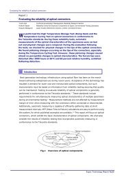
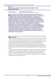
Measuring Conductivity of Proton Conductive Membrane in the direction of thickness, partⅡ:<br />
using the 4-probe method in the direction of thickness<br />
Report<br />
Measuring Conductivity of Proton Conductive Membrane in the direction of<br />
thickness, part Ⅱ: using the 4-probe method in the direction of thickness<br />
Shuhua Ma, Hirokazu Tanaka Technical Development Headquarters<br />
P<br />
roton conductive membrane has been reported to exhibit anisotropic<br />
properties in its in-plane and thickness directions in such areas as crystalline<br />
structure, dimensional stability, and proton conductivity. 1),2) Generally, the<br />
conductivity of proton conductive membrane is measured only in the in-plane<br />
direction due to the availability of well-developed methods. However, these<br />
measurements do not provide a complete and accurate grasp of the conduction<br />
properties of a membrane. As a result, methods of measuring ion conductivity in the<br />
direction of thickness are urgently required, especially with the successful use during<br />
recent decades of proton exchange membranes in polymer electrolyte membrane fuel<br />
cells (PEFCs). Unfortunately, an accurate and reliable method has yet to be<br />
established for measuring ion conductivity in the direction of thickness of the<br />
membrane.<br />
Usually, higher accuracy is attained using the 2-probe and 4-probe methods to<br />
measure conductivity in the in-plane direction. At Espec, we have investigated the<br />
possibility of applying these methods for measuring conductivity in the direction of<br />
membrane thickness. Preceding reports 2),3),4) have discussed the effects of interface<br />
complexity and contact quality between test membrane and electrodes, and have<br />
verified the feasibility of employing the 2-probe method for measuring ion<br />
conductivity in the direction of thickness. On the other hand, the 4-probe method can<br />
yield much more accurate measurements than the 2-probe method because it uses<br />
reference electrodes to sample electrical potentials on both sides of test membranes.<br />
This report will present results obtained using the 4-probe method in the direction of<br />
thickness for measuring the conductivity of ion exchange membranes.<br />
- 1 -<br />
Espec Technology Report No.23
Measuring Conductivity of Proton Conductive Membrane in the direction of thickness, partⅡ:<br />
using the 4-probe method in the direction of thickness<br />
1<br />
Introduction<br />
Compared to measuring in the in-plane direction, the 4-probe method of measuring in the<br />
direction of thickness features a much smaller cell constant (L/A in σ=L/(RA))because the<br />
membrane is thinner and possesses a larger area. Consequently, the measured resistance,<br />
typically within the range of 0.1 to 50Ω, is significantly lower than that in the in-plane direction<br />
when using the 4-probe method, in which resistance can be as high as 10 to 10 4 Ω according to<br />
the temperature and humidity environments used. When measuring in the direction of thickness<br />
with the 4-probe method, some new problems may hinder widespread practical application.<br />
(1) Dispersion in measurement values may be incurred by unevenness of interlayers in<br />
membrane laminates and/or contact between the reference electrode and its adjacent<br />
membranes. Such dispersion may also be induced by the MEA (membrane/electrode<br />
assembly) from the much thicker wire diameter of the reference electrodes.<br />
(2) A much larger contact area between the reference electrode (which samples electric potential<br />
on one face of the test membrane) and the test membrane, which may come from the<br />
exfoliation and/or the crumbling of the coating layer on the reference electrode, will<br />
(a) produce rather larger interface resistance than bulk test membrane and smaller interface<br />
capacitance between the test membrane and the reference electrodes. With these<br />
influences, some labile arc-like loops and/or semi-circles may arise in the Cole-Cole plot,<br />
which will make it impossible for the 4-probe method to avoid being influenced by effects<br />
related to interfaces.<br />
(b) cause the hemi-circles on the Cole-Cole plot to be unsteady due to changes in the contact<br />
area between the reference electrodes and membrane, and to be susceptible to the<br />
fluctuations of the temperature and the humidity in the operating environment.<br />
Furthermore, this mutability makes it impossible to measure bulk resistance of the<br />
membrane by intercepting on a real axis such as is done in 2-probe method.<br />
(3) When MEA specimens are produced at higher temperatures and pressures using<br />
hot-pressing, reference electrodes frequently break off from the wires sandwiched between<br />
test membranes and current lead-in membranes, causing functional failure. This is caused by<br />
the creep property of the polymeric membranes that are liable to stretch and deform.<br />
- 2 -<br />
Espec Technology Report No.23
Measuring Conductivity of Proton Conductive Membrane in the direction of thickness, partⅡ:<br />
using the 4-probe method in the direction of thickness<br />
Because of these problems, input/output O/L (overload) error messages of current and voltage<br />
in the electrochemical measurement device (Potentiostat/Galvanostat) are much more likely to<br />
occur when using the 4-probe method in the direction of thickness than in the in-plane direction.<br />
The difficulties in manufacturing and measuring MEA specimens have greatly hindered the<br />
application of the 4-probe method in the direction of thickness in real ion conductivity<br />
measurements. Furthermore, a defective MEA specimen produced by improper temperature and<br />
pressure conditions will also lead to some failures and debase the accuracy of the measurements.<br />
For example, diffuse and scattered points with a poor convergence domain are brought about on<br />
the Cole-Cole plot, and/or completely singular resistance measurements may be obtained.<br />
With the aim of overcoming the above failures and identifying the optimal specimen<br />
manufacturing conditions as well as conditions for accurately measuring proton conductivity in<br />
the direction of thickness of Nafion ® -like membranes, we at Espec have developed the 4-probe<br />
technique in the direction of thickness. This report will discuss some important factors affecting<br />
the measuring performance of the MEA specimen, including the arrangement between the<br />
electric potential sampling electrodes and the electric current lead-in membranes, materials of<br />
the wire and its coating used as electric potential sampling electrodes, and the forming condition<br />
of MEA specimens. In addition, this report will also present measurement results from this<br />
4-probe technique in the direction of thickness for Nafion117 ® membranes that underwent<br />
different temperature and pressure pretreatments.<br />
2<br />
Experimental method<br />
2-1 Equipment and materials<br />
Table 1 lists equipment and materials used in this research.<br />
Table 1 Equipment and materials<br />
Equipment/materials Manufacturer<br />
Ion exchange membrane<br />
Cu/polyester coated wire,<br />
wire diameter: φ0.1mm<br />
Pt/Teflon coated wire,<br />
wire diameter: φ0.076mm<br />
E. I. du Pont de Nemours and<br />
Company<br />
- 3 -<br />
Model/registered<br />
product name<br />
Nafion117 ®<br />
The Nilaco Corporation CU-116167<br />
The Nilaco Corporation PT-967353<br />
Pt wire, wire diameter:φ0.10mm The Nilaco Corporation PT-351165<br />
Insulating varnish The Nilaco Corporation Varnish, No. 7031<br />
Impedance gain/phase analyzer Solartron Instruments SI 1260<br />
Electrochemical interface Solartron Instruments SI 1287<br />
Temperature & humidity chamber Espec Corporation PL-1KPH<br />
Espec Technology Report No.23
Measuring Conductivity of Proton Conductive Membrane in the direction of thickness, partⅡ:<br />
using the 4-probe method in the direction of thickness<br />
2-2 Specimen preparation<br />
2-2-1 Preparation of reference electrodes<br />
Three types of coated wire with insulating layer were used as reference electrodes (also known<br />
as electric potential sampling electrodes) to examine effects of the coating and the conducting<br />
materials on the measuring performance of the MEA specimen.<br />
(a) Cu/polyester coated wire: ready-made product used as listed in Table 1.<br />
(b) Pt/Teflon coated wire: ready-made product used as listed in Table 1.<br />
(c) Pt/insulating varnish coated wire: coating film formed on Pt wire by soaking bare Pt wire in<br />
Varnish No. 7031 solution diluted with solvent mixture of ethyl alcohol and toluene 50:50 by<br />
volume, and followed by drying in vacuum at 100℃ for 5 hours.<br />
2-2-2 Manufacturing MEA specimens for the 4-probe method in the direction of thickness<br />
Using the above three types of coated wires, reference electrodes were prepared by cutting one<br />
end obliquely to be used as the electric potential sampling electrode terminal and peeling the<br />
other end of the wire about 1 cm to be used as the connecting terminal into other external<br />
devices.<br />
Two steps were involved in the manufacturing process of premium MEA specimens in this<br />
context.<br />
First, the reference electrode was imbedded into the current lead-in membrane by placing one<br />
reference electrode on a 50μm-thick Teflon sheet with its bevel section exactly toward the film<br />
surface, covering that with a current lead-in membrane and another Teflon sheet in sequence,<br />
and then following with a hot-pressing treatment at 150℃ and 400 kgf cm -2 . Second, after<br />
removing the Teflon sheets, the MEA specimen was fabricated by sandwiching two current<br />
lead-in membrane units made above and one test membrane pretreated under the appointed<br />
temperature, pressure and chemical conditions, with the bevel sections situated opposite each<br />
other and located at equipotential positions, e.g., the center of the test membrane, and then<br />
hot-pressing them at 150℃ and 20 kgf cm -2 . The schematic construction of the MEA specimen as<br />
obtained above for the 4-probe method in the direction of thickness is shown in Fig.1.<br />
- 4 -<br />
Espec Technology Report No.23
Measuring Conductivity of Proton Conductive Membrane in the direction of thickness, partⅡ:<br />
using the 4-probe method in the direction of thickness<br />
Fig.1 Construction of MEA specimen for the 4-probe method in the direction of<br />
thickness<br />
2-3 Conductivity measurement of MEA specimens<br />
A specimen fixed to the measuring cell was placed inside a temperature and humidity chamber<br />
under constant temperature and humidity (30℃, 30-90%rh). AC impedance measurements<br />
were taken using a computer-controlled impedance gain/phase analyzer and electrochemical<br />
interface measuring system, and Cole-Cole (Z’-Z’’) and Bode (log|Z|-log Frequency and<br />
theta-log Frequency) plots were obtained. The frequency limits of the sinusoidal signals were<br />
typically set between 5MHz and 0.01Hz, with an oscillation of 10 mV.<br />
With test membrane bulk resistance R read out according to the center of gravity of the<br />
concentrated points on Cole-Cole plot, conductivity was calculated using the following formula.<br />
L<br />
=<br />
R ⋅ A<br />
σ … (1)<br />
Where σ is conductivity (S cm -1 ), R is resistance (Ω), L is test membrane thickness or interval<br />
between two electric potential sampling electrodes (cm), and A is electrode area (cm 2 ).<br />
Equipment connection for the impedance gain/phase analyzer (IGPA), the electrochemical<br />
interface (EI) and the membrane/electrode assembly (MEA) was shown in Fig.2 for 4-probe<br />
conductivity measurements in the thickness direction used in this report.<br />
- 5 -<br />
Espec Technology Report No.23
Measuring Conductivity of Proton Conductive Membrane in the direction of thickness, partⅡ:<br />
using the 4-probe method in the direction of thickness<br />
Fig.2 Block configuration for ion conductivity measurement using the 4-probe<br />
method in the direction of thickness<br />
3<br />
Considerations and discussion of measuring<br />
3-1 Configuration of the 4-probe method in the direction of thickness<br />
Using the 4-probe method in the direction of thickness, the simplest configuration is that which<br />
measures only a single test membrane, although theoretically multiple membranes can be<br />
measured unless the MEA stack is too thick to afford stable and sound internal contacts as well a<br />
dimensional evenness of the test membranes. As Fig.2 shows, a typical MEA specimen<br />
configuration consists of 4 electrodes, known as electric current lead-in electrodes and electric<br />
potential sampling electrodes, and 3 membranes as electric current lead-in membranes and test<br />
membrane. Considering the specimen as an active electrochemical system, the equivalent<br />
circuit 5) and the connections into the external electrochemical device can be expressed in Fig.3.<br />
- 6 -<br />
Espec Technology Report No.23
Measuring Conductivity of Proton Conductive Membrane in the direction of thickness, partⅡ:<br />
using the 4-probe method in the direction of thickness<br />
- 7 -<br />
RmCE, RctCE, CdlCE: denote resistance and<br />
capacitance related to the electric current<br />
lead-in membrane and the interface between<br />
that and the electric current lead-in electrode<br />
on the CE side.<br />
Rm, RctRE1, CdlRE1, RctRE2, CdlRE2: denote<br />
resistance and capacitance related to the test<br />
membrane, and the interfaces between that<br />
and reference electrodes.<br />
RmWE, RctWE, CdlWE: denote resistance and<br />
capacitance related to the electric current<br />
lead-in membrane and the interface between<br />
that and the electric current lead-in electrode<br />
on the WE side.<br />
Where subscript CE stands for the electric current lead-in electrode or membrane on the CE side,<br />
RE1 for the electric potential sampling electrode on the CE side, m for the test membrane, RE2<br />
for the electric potential sampling electrode on the WE side, WE for the electric current lead-in<br />
electrode or membrane on the WE side, respectively. Furthermore, ct and dl refer to charge<br />
transfer and double layer as conventionally for an electrochemical interface.<br />
Fig.3 Connections and equivalent circuit for MEA specimen using the 4-probe method<br />
in the direction of thickness<br />
Espec Technology Report No.23
Measuring Conductivity of Proton Conductive Membrane in the direction of thickness, partⅡ:<br />
using the 4-probe method in the direction of thickness<br />
Fig.3 demonstrates that the impedance pertaining to the electric current lead-in membrane and<br />
its interfaces with electric current lead-in electrodes, RmCE, RmWE, and RctCE, RctWE, CdlCE, CdlWE, are<br />
situated outside the electric potential sampling measurement system, and thus have little<br />
influence on measurement results. As a result, bulk membrane resistance Rm can be measured<br />
accurately using this method, provided the impedance related with RctRE1, RctRE2, and CdlRE1, CdlRE2 are small enough. This impedance can be reduced by adjusting hot-pressing conditions and<br />
manufacturing processes of MEA specimens. Hence, we may infer that the electric current lead-in<br />
electrodes, CE and WE, may be omitted by substituting two electrode terminals of the measuring<br />
cell. Also, the electric current lead-in membranes of CE and WE do not affect the results even if<br />
different kinds and/or thickness of membranes are used, although they should possess the same<br />
current-conducting carriers as the test membrane, viz., either electron, proton, or other ions. In<br />
addition, test membranes can be pretreated by hot-pressing at various pressures and<br />
temperatures, or any chemical treatments may be applied before preparing MEA specimens.<br />
Thus, this method allows a wide range of membrane conditions.<br />
However, it is necessary to prevent the thickness and the evenness of test membranes from<br />
being affected when the test membrane is combined into an MEA specimen. This means that<br />
temperature and pressure conditions must be neither too high nor too low when hot-pressing for<br />
successfully preparing MEA specimens. In this report, we have reported a two-step method by<br />
which reference electrodes were completely imbedded into electric current lead-in membranes in<br />
the first step. Because of this, we were able to use fairly reduced temperature and pressure<br />
conditions without markedly disturbing test membranes in the following second step.<br />
Consequently, the accuracy, reliability and reproducibility of the ion conductivity measurements<br />
using the 4-probe method in the direction of thickness have been significantly enhanced.<br />
3-2 Identifying cause of failure of MEA specimens from O/L error messages in<br />
electrochemical measurement<br />
When using the impedance gain/phase analyzer and electrochemical interface measuring<br />
system of Solartron Instruments to measure the proton conductivity in the direction of thickness<br />
of polymeric electrolyte membrane using the 4-probe method, RE1 O/L, RE1-RE2 O/L, and<br />
Current O/L and Current DVM O/L errors frequently occurred on the Potentiostat/Galvanostat<br />
electrochemical device (Model 1287, electrochemical interface). 6) These messages, combined<br />
with the measuring principle of the electrochemical device used, may work as an informative<br />
guide for determining the failure cause of the MEA specimen, i.e., what defects have been<br />
observed and/or what failures have developed when measuring MEA specimens. For example,<br />
the appropriate conditions for the manufacture and measurement of MEA specimens can be<br />
found more effectively and rapidly based on analyses of these errors.<br />
- 8 -<br />
Espec Technology Report No.23
Measuring Conductivity of Proton Conductive Membrane in the direction of thickness, partⅡ:<br />
using the 4-probe method in the direction of thickness<br />
As mentioned in the connections and equivalent circuit of MEA specimen while measuring by the<br />
membrane thickness 4-probe method in Fig.3, the Potentiostat/Galvanostat was used to apply<br />
AC potential perturbation to the terminals of CE and WE while simultaneously sampling the<br />
electric potential signals between the terminals of RE1 and RE2. When error messages of RE1 O/L<br />
and/or RE1-RE2 O/L occur, they indicate that a higher voltage drop than the 14.5 V limit of the<br />
device has developed between the terminals of RE1 and the ground and/or the terminals of RE1<br />
and RE2. An important phenomenon found while measuring is that the error messages RE1 O/L<br />
and RE1-RE2 O/L occurred simultaneously during the measuring period with a frequency range<br />
lower than 10 kHz. With the WE terminal as the ground for the instrument as shown in Fig.3, it<br />
can only be concluded that the impedance between the terminals of RE1 and RE2 rather than that<br />
between RE2 and WE was overloaded. This may have come from excessive interface resistance<br />
or insufficient interface capacitance (or both) for reference electrodes RE1 and RE2, as shown in<br />
Fig.3. Excessive interface resistance RctRE1 or RctRE2 is thought to have come from poor contact<br />
between the test membrane and reference electrode RE1 or RE2, or disconnected electrode<br />
wires. The following causes of failure can be expected: the snapping-off of electrode wires, the<br />
shielding of electrode terminals by the insulated coating tube or its fragments that may come<br />
from the stretching forward and/or the breaking up of the coating layer of the electrode wire, and<br />
unstable contact between the reference electrode and the test membrane.<br />
4<br />
Observations and discussion for measuring<br />
4-1 Effect of manufacturing conditions of MEA specimens<br />
Effects of hot-pressing conditions and reference electrode materials on MEA measuring<br />
performance are listed in Table 2 for measurements of proton conductivity of Nafion117 ®<br />
membrane using the 4-probe method in the direction of thickness using the AC impedance<br />
technique.<br />
- 9 -<br />
Espec Technology Report No.23
Measuring Conductivity of Proton Conductive Membrane in the direction of thickness, partⅡ:<br />
using the 4-probe method in the direction of thickness<br />
Table 2 Effects of hot-pressing conditions and electrode material<br />
on MEA measuring performance<br />
Hot-pressing temperature<br />
/ pressure<br />
Forming method<br />
/ electrode material<br />
One-step<br />
Two-step*<br />
Teflon-Pt<br />
Varnish-Pt<br />
Polyester-Cu<br />
150℃ 80℃<br />
40 kgf cm -2 200 kgf cm -2 400 kgf cm -2 40 kgf cm -2 200 kgf cm -2 400 kgf cm -2<br />
Stretched<br />
coating<br />
Unstable<br />
performance<br />
Poor<br />
performance<br />
Wire break,<br />
Stretched<br />
coating<br />
- 10 -<br />
Wire break,<br />
Stretched<br />
coating<br />
Wire break Wire break<br />
Poor<br />
performance<br />
Wire break<br />
Teflon-Pt - - -<br />
Varnish-Pt - - -<br />
Polyester-Cu - - -<br />
Stretched<br />
coating<br />
Unstable<br />
performance<br />
Good<br />
performance<br />
Stretched<br />
coating<br />
Good<br />
performance<br />
Excellent<br />
performance<br />
Wire break,<br />
Stretched<br />
coating<br />
Wire break,<br />
Stretched<br />
coating<br />
Wire break Wire break<br />
Poor<br />
performance<br />
Stretched<br />
coating<br />
Unstable<br />
performance<br />
Good<br />
performance<br />
Poor<br />
performance<br />
Wire break,<br />
Stretched<br />
coating<br />
Poor<br />
performance<br />
Unstable<br />
performance<br />
*:Reference electrode wires were previously imbedded into electric current lead-in membranes<br />
by hot-pressing at 150℃ and 400 kgf cm -2 for 1 min in the first step<br />
The one-step method in MEA manufacturing refers to a technique in which the MEA specimen is<br />
completed using a single hot-pressing process with the laminate stack sandwiched by two electric<br />
current lead-in membranes, two reference electrode wires, and one test membrane. Using the<br />
one-step method, shown in Table 2, MEA specimens prepared at relatively lower temperature or<br />
pressure afforded a comparatively higher measuring performance for all three reference<br />
electrode materials used, more obviously in the case of Cu/polyester coated wire. On the other<br />
hand, measuring performance of the MEA specimens was enhanced dramatically with the<br />
two-step method, which features a preceding hot-pressing process by which the reference<br />
electrode was imbedded into the electric current lead-in membranes. The results exhibited the<br />
marked effectiveness of the two-step method over the one-step method. Moreover, Table 2 also<br />
reveals an increase in the measuring performance of the MEA specimens with the use of<br />
electrode material in the following order: Pt/Teflon, Pt/varnish, and Cu/polyester.<br />
Microscope analysis was used to clarify the mechanism of failure of the MEA specimens,<br />
observing and analyzing reference electrodes that underwent hot-pressing treatments. Typical<br />
failure examples of reference electrodes are shown in Photo 1. These failures occurred after first<br />
undergoing a hot-pressing process in the first step when using the two-step method.<br />
Espec Technology Report No.23
Measuring Conductivity of Proton Conductive Membrane in the direction of thickness, partⅡ:<br />
using the 4-probe method in the direction of thickness<br />
Polyester-Cu<br />
Hot-pressing: 150℃, 400kgf cm -2<br />
10 min<br />
Snapping-off of Cu wire and breaking-up of the<br />
coating layer can be observed due to the higher<br />
temperature and pressure, and the longer<br />
hot-pressing time.<br />
Polyester-Cu<br />
Hot-pressing: 150℃, 40kgf cm-2 1 min<br />
With lower pressure and shorter hot-pressing time,<br />
the integrity of the reference electrode was<br />
significantly improved. As less pressure than 40kgf<br />
cm-2 was applied, the adherence of the electrode into<br />
the electric current lead-in membrane degraded.<br />
However, shortened pressing time was viable.<br />
Varnish-Pt<br />
Hot-pressing: 150℃, 400kgf cm -2<br />
1 min<br />
Identical conditions to (A) except time of<br />
hot-pressing. However, marked cutting was induced.<br />
The result is considered as due to poor malleability of<br />
Pt wire compared to Cu.<br />
Photo 1 Typical failure examples of reference electrodes occurring after the first<br />
hot-pressing process in the two-step method<br />
- 11 -<br />
Espec Technology Report No.23
Measuring Conductivity of Proton Conductive Membrane in the direction of thickness, partⅡ:<br />
using the 4-probe method in the direction of thickness<br />
Photo 1 (C) exhibits an important conclusion to be drawn: a conductor with excellent<br />
malleability should be selected as the reference electrode, e.g., Au wire other than Pt should be<br />
used instead of Cu wire when a strongly corrosive environment is involved.<br />
On the other hand, we also tried using Teflon-Pt-coated wire as the reference electrode and<br />
observed the MEA specimen. We found that besides causing the wire to snap off and breaking up<br />
the coating layer, the Teflon coating layer became badly elongated and covered the entire<br />
conducting tip of the electrode. This result is considered to stem from weaker adherence between<br />
the surface of the Pt wire and the Teflon coating layer when hot-pressed at the specified<br />
treatment temperature.<br />
From the above observations, it has been confirmed that the stretching, breaking up and<br />
covering of the coating layer on the reference electrode as well as the cutting of the conducting<br />
wire have independently and/or jointly resulted in occurrences of O/L error messages in the<br />
electrochemical device.<br />
In summary, the following measures are very important to a better measuring performance of<br />
the MEA specimen: adapting the two-step method, selecting the proper hot-pressing<br />
temperature, pressure, and time while taking into account both the firmness and the integrity of<br />
the reference electrode, and choosing the suitable conducting and coating materials for the<br />
reference electrode based on the applied membrane environment.<br />
4-2 Influencing of the measuring cell<br />
As described above, it is important to manufacture an MEA specimen free of any inherent<br />
defects. Furthermore, it is also necessary for a custom-designed measuring cell to be used to<br />
connect the ultra-fine reference electrode terminal of approximately 100 μm in diameter with<br />
external electrochemical devices, because connection reliability exerts a major influence on<br />
measurability and accuracy. A special measuring cell has been designed intended for exclusive<br />
use with the 4-probe method in the direction of thickness. This cell provides easy connecting<br />
operation, stable and unaffected internal contact in the MEA specimen while connecting, and the<br />
necessary external connection reliability.<br />
- 12 -<br />
Espec Technology Report No.23
Measuring Conductivity of Proton Conductive Membrane in the direction of thickness, partⅡ:<br />
using the 4-probe method in the direction of thickness<br />
4-3 Proton conductivity measurement in the direction of thickness with the Nafion117 ®<br />
membrane<br />
The 2- and 4-probe methods in the direction of thickness and the 4-probe method in the<br />
in-plane direction were used to study the proton-conducting properties of the Nafion117 ®<br />
membrane pretreated by hot-pressing at 150℃ at various pressures. Fig.4 shows typical<br />
impedance spectra for membranes pretreated at 150℃ and 1200 kgf cm -2 . These were obtained<br />
using the membrane thickness 4-probe method in an environment of 30℃ at 60%rh.<br />
Near constant resistance and almost 0o of phase angle were obtained in Bode plots (A) and (B)<br />
within the frequency range of between 0.01 Hz and 9000 Hz. Meanwhile, concentrated points with<br />
a narrow convergence domain were displayed in the Cole-Cole plot of Fig.4(C). These results<br />
indicate that the 4-probe method in the direction of thickness is viable in practice, exhibiting good<br />
measurement accuracy.<br />
Measurement environment: 30℃, 60%rh<br />
Membrane treatment: 150℃, 1200 kgf cm -2<br />
A and B: Bode plots, C: Cole-Cole plot<br />
Inset shows detail of concentrated point.<br />
Fig.4 Typical impedance spectra obtained using the 4-probe method in the direction<br />
of thickness for Nafion117 ® membrane<br />
- 13 -<br />
Espec Technology Report No.23
Measuring Conductivity of Proton Conductive Membrane in the direction of thickness, partⅡ:<br />
using the 4-probe method in the direction of thickness<br />
Fig.5 showed the measurement values for Nafion117 ® pretreated at 150℃ at various pressures<br />
using the membrane plane 4-probe method and membrane thickness 2- and 4-probe methods.<br />
Here, it should be noted that as a comparison standard, the measurements for these membranes<br />
were also carried out using the conventional 4-probe method in the in-plane direction and the<br />
2-probe method in the direction of thickness. For membranes pretreated at 150℃ and 1200 kgf<br />
cm -2 , the proton conductivity values measured using the 2- and 4-probe methods in the direction<br />
of thickness fit very well, verifying the effectiveness of the 4-probe method in the direction of<br />
thickness. However, when compared to measuring in the in-plane direction using the 4-probe<br />
method, proton conductivity values in the direction of thickness were found to have significantly<br />
decreased. In order to make clear the actual causes, i.e., either from the immaturity of the<br />
measurement technology developed or from the degenerated property of the membrane,<br />
measurements were also carried out using the 4-probe methods in the in-plane and thickness<br />
directions to measure a membrane heat-treated at 150℃ but not pressurized.<br />
As Fig.5 shows, good conformity exists for the measurements not only between the values in the<br />
in-plane and thickness directions for the membrane pressurized at 0 kgf cm -2 but also with those<br />
in the in-plane direction for the membrane treated at 1200 kgf cm -2 . These results indicate that<br />
after hot-pressing at higher temperature and pressure, proton conductivity in the direction of<br />
thickness of the Nafion117 ® membrane was significantly degraded. Merely a simple heat<br />
treatment with no pressurizing process did not induce the marked anisotropy in the proton<br />
conductance of the membrane.<br />
Measurement environment: 30℃, 30, 60, and 90%rh<br />
Membrane treatment: 150℃, 0 and 1200 kgf cm -2<br />
Fig.5 Proton conductivity measurements using the 4-probe method in the in-plane<br />
direction, and the 2- and 4-probe methods in the direction of thickness for<br />
Nafion117 ® membrane<br />
From the above we may conclude that the 4-probe method may be employed in the direction of<br />
thickness and this method is conducive to the complete evaluation of the ion conductance of the<br />
electrolyte membrane with higher stability, accuracy and reproducibility.<br />
- 14 -<br />
Espec Technology Report No.23
Measuring Conductivity of Proton Conductive Membrane in the direction of thickness, partⅡ:<br />
using the 4-probe method in the direction of thickness<br />
5<br />
(1) More attention should be paid to the following items as influencing factors in the 4-probe<br />
method in the direction of thickness: the species and characteristics of the conductor and the<br />
coating layer materials constituting reference electrodes, the method of fabricating MEA<br />
specimens, the temperature and pressure conditions in hot-pressing, and connections with<br />
external devices.<br />
(2) Anisotropic ion conductance can be induced over the directions of thickness and in-plane for<br />
Nafion117 ® -like electrolyte membranes when pretreated at higher temperature and<br />
pressure.<br />
(3) The 4-probe technique may be employed in the direction of thickness in real measurements<br />
of the ion-conducting electrolyte membrane.<br />
6<br />
Conclusions<br />
Acknowledgement<br />
The authors would like to express their gratitude to Mr. Zyun Siroma of the National Institute of<br />
Advanced Industrial Science and Technology (AIST) for helpful instruction and useful discussions.<br />
[Bibliography]<br />
1) K. M. Cable et al., Chem. Mater., 7, p.1601, 1995.<br />
2) Shuhua Ma and Zyun Siroma, Proceedings of the 46th Battery Symposium in Japan, 2G-18,<br />
2005.<br />
3) Shuhua Ma, Akiko Kuse, Zyun Siroma and Kazuaki Yasuda, Espec Technology Report, No. 20,<br />
P.12-20, 2005.<br />
4) Shuhua Ma, Zyun Siroma and Hirokazu Tanaka, J. Electrochem. Soc., Vol. 153, No. 12,<br />
A2274-A2281, 2006.<br />
5) C. H. Lee et al., Ind. Eng. Chem. Res., Vol. 44, p. 7617-7626, 2005.<br />
6) Solartron Instruments, Model 1287 Electrochemical Interface, Instruction manual, issued by<br />
TOYO corporation.<br />
- 15 -<br />
Espec Technology Report No.23
Introducing ESPEC EUROPE GmbH<br />
Topic<br />
Introducing ESPEC EUROPE GmbH<br />
Masago Iwashima, Espec Europe GmbH<br />
1<br />
Introduction - A letter from Yoshinobu Matsumura, Managing Director -<br />
Photo 1 Yoshinobu Matsumura, Managing Director, Espec Europe GmbH<br />
Greetings,<br />
I am Yoshinobu Matsumura, Managing Director, Espec Europe GmbH. I would like to express<br />
my sincere appreciation for your continued patronage of Espec and our products.<br />
First, I would like to give a brief overview of how Espec has approached our dealings in the<br />
European market to this point. In 1988, Espec established a local corporation in Europe and<br />
began pursuing business development in Europe and in the old Soviet Union. Despite our efforts<br />
to expand into the Soviet market, shortly thereafter, as I’m sure you are well aware, the Soviet<br />
Union collapsed. Being considerably affected by that collapse, our temporary withdrawal<br />
became unavoidable. However, within the scope of our global development, the European<br />
market holds substantial promise, and we foresee tremendous improvement in the Russian<br />
market as well, leading to our renewed efforts to take up this challenge once more after a<br />
15-year hiatus.<br />
In August 2004, we stationed representatives at an office we established in Frankfurt. In 2005,<br />
we moved our location to Munich, where our organizational framework evolved to a branch<br />
office. While a number of significant challenges remain, we are indebted to your patronage that<br />
has contributed to our favorable business results. In addition, from October 1, 2006, our new<br />
line-up is available. We have also established the new Espec Europe GmbH, which is operating<br />
in Munich. Based on the management philosophy of the Espec Group, we are striving to achieve<br />
a “corporation of global excellence” to develop a global business that is based on a management<br />
framework of transparency and respect for the laws and that meets the expectations of our<br />
global customers.<br />
As a European marketing company, our primary theme is to improve the satisfaction rate of our<br />
valued customers. Based on the structure of our local operational framework and our global<br />
network in each country, we are striving to make our support framework even better for each<br />
valued customer in the EU and Russia.<br />
We are indebted to you all for your continued patronage of Espec and our products.<br />
Yoshinobu Matsumura, Managing Director, Espec Europe GmbH<br />
- 16 -<br />
Espec Technology Report No.23
Introducing ESPEC EUROPE GmbH<br />
2<br />
The mission of Espec Europe GmbH<br />
2-1 With the establishment of Espec Europe GmbH comes our commitment: improving<br />
service to our valued customers<br />
“To promote viewing, using, and knowing the value of Espec products”<br />
1. Closer operation : We are supplying services from a location that is closer to the<br />
customer geographically and in time. We are actively participating in<br />
activities such as exhibitions within the various European countries.<br />
2. Better inventory : We will provide European inventory for products with strong demand:<br />
Except for special order items, Espec will secure inventory for standard<br />
products in an effort to provide much quicker delivery than has been<br />
available.<br />
3. More complete service : Our well-trained staff, proficient in English, German, and Japanese,<br />
and including technical experts, are well prepared to respond promptly<br />
and in detail to your inquiries. (We shall introduce the staff below.)<br />
2-2 Examples of products handled by Espec Europe GmbH -Latest information-<br />
For details, visit our web site:http://www.espec.co.jp/english/products/products.html<br />
Thermal Shock Chamber TSD-100<br />
Two-zone thermal shock chamber ideally suited for<br />
MIL/IEC/JASO test standards.<br />
This new Thermal Shock Chamber is capable of subjecting<br />
specimens to uniform thermal stress with a 100 L test area<br />
and outstanding thermal distribution characteristics, making<br />
them ideally suited for use in a wide range of applications<br />
from research and development to inspection and<br />
production.<br />
- Compatible with MIL-STD-883 and other test standards<br />
- Improved temperature distribution performance<br />
- Reduced test time by moving between two test areas<br />
- Incorporate new Specimen Temperature Trigger (STT)<br />
function<br />
- Reduced power consumption<br />
- 17 -<br />
Espec Technology Report No.23
Introducing ESPEC EUROPE GmbH<br />
Rapid-Rate Thermal Cycle Chamber TCC-150<br />
Electromigration Evaluation System (AEM-2000)<br />
Advent of the Rapid-Rate Thermal Cycle Chamber just<br />
suited for quick changes in specimen temperature, covering<br />
various applications from JEDEC standard tests to<br />
screening.<br />
The Rapid-Rate Thermal Cycle Chamber incorporates new<br />
technologies, such as a specimen temperature control that<br />
maintains linear specimen temperature change rates,<br />
during rapid thermal cycling, and temperature ramp control.<br />
Espec offers a new chamber that sets the industrial standard<br />
for the new era of thermal cycling.<br />
- Conformity to JEDEC (JESD22-A104-B) standard test<br />
- New temperature ramp control functions<br />
- Specimen temperature control and air temperature control<br />
- Uniform temperature load and highly repeatable<br />
temperature change rate.<br />
Increasing use is being made of microfabrication and new<br />
materials in order to increase the levels of performance and<br />
integration achieved with semiconductor devices. And as the<br />
operating life of devices depends on microfabrication and<br />
such new materials, it has become increasingly important to<br />
evaluate electromigration under high-precision<br />
life-acceleration conditions. High-precision control is used<br />
for the temperature (max. 400℃) and current stress that<br />
form the main factors in this life acceleration. A Black's<br />
model equation and analytical software have been provided<br />
to determine product life.<br />
- Electromigration testing is available at 1μA, 400℃<br />
- Capable of testing up to 240 channels per cabinet<br />
- Newly developed highly reliable board and socket<br />
- 18 -<br />
Espec Technology Report No.23
Introducing ESPEC EUROPE GmbH<br />
3<br />
Introducing the Espec GmbH staff<br />
These are the members of the Espec GmbH staff. They will be pleased to assist you with any<br />
inquiries.<br />
Mitsuru Yui<br />
Manager<br />
Service Department<br />
Language proficiency: Japanese, English<br />
Christian Witte<br />
Finance & Administration Manager<br />
Language proficiency: German, English<br />
(Studying Japanese)<br />
Photo 2 Espec GmbH staff (1)<br />
- 19 -<br />
Frank Feiler<br />
Area Manager<br />
Language proficiency: German, English,<br />
Japanese<br />
Masago Iwashima<br />
Marketing Assistant<br />
Sales Department<br />
Language proficiency: Japanese, English<br />
(Studying German)<br />
Espec Technology Report No.23
Introducing ESPEC EUROPE GmbH<br />
4<br />
Christine Spath<br />
Sales & Marketing<br />
Language proficiency: German, English<br />
Introducing our new office<br />
- 20 -<br />
Gabriele Opl<br />
Accounting<br />
Language proficiency: German, English<br />
Photo 3 Espec GmbH staff (2) -Consultants-<br />
Coinciding with the establishment of Espec GmbH, we began operations at our new location<br />
from October 1, 2006. We are situated in the main district of Munich quite near the central station,<br />
with very convenient public access. We would be honored to have you come by our office any time<br />
you are in Munich. All of our staff is sincerely looking forward to your visit.<br />
Photo 4 Location of our new office<br />
Espec Technology Report No.23
Introducing ESPEC EUROPE GmbH<br />
Access<br />
(1) By public transportation:<br />
Get off the train at Hauptbahnhof (Central<br />
Station) and take the Nord Seite exit (exit<br />
escalator next to the Blumen Knauer flower<br />
shop). Go straight ahead on Dachauer Strasse<br />
(between Schlecker and Pension). We are<br />
about 5 minutes from the station on foot. (Our<br />
entrance is on the Dachauer Strasse side,<br />
between the Plus supermarket and the King’s<br />
Hotel.)<br />
(2) By car:<br />
Please use the public parking near our office.<br />
- 21 -<br />
Fig.1 Office map<br />
Below is our address and contact information. We shall be pleased to provide our full guidance and<br />
support to our valued friends.<br />
ESPEC EUROPE GmbH<br />
Address : Dachauer Strasse 11, D-80335 München<br />
Tel. : +49(0)89 1893 963-0 (main)<br />
Fax. : +49(0)89-1893 963-79<br />
URL : http://www.espec.de/<br />
E-mail : info@espec.de<br />
<br />
EU Sales Department, International Business Headquarters,<br />
Espec Corporation<br />
Tel. : +81-6-6358-4785<br />
Fax. : +81-6-6358-4786<br />
Espec Technology Report No.23