Evaluating the reliability of optical connectors
Evaluating the reliability of optical connectors
Evaluating the reliability of optical connectors

You also want an ePaper? Increase the reach of your titles
YUMPU automatically turns print PDFs into web optimized ePapers that Google loves.
<strong>Evaluating</strong> <strong>the</strong> <strong>reliability</strong> <strong>of</strong> <strong>optical</strong> <strong>connectors</strong><br />
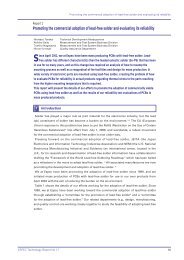
Report 1<br />
<strong>Evaluating</strong> <strong>the</strong> <strong>reliability</strong> <strong>of</strong> <strong>optical</strong> <strong>connectors</strong><br />
Yuichi Aoki Technical Development Headquarters, Reliability Research Section<br />
Kishichi Sasaki Reliability Center for Electronic Components <strong>of</strong> Japan, Environmental Testing Laboratory<br />
Kiyoyuki Mutaguchi Japan Aviation Electronics Industry, Limited, Connector Division<br />
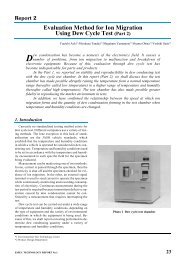
W<br />
e performed <strong>the</strong> High Temperature Storage Test (Damp Heat) and <strong>the</strong><br />
Temperature Cycling Test on <strong>optical</strong> <strong>connectors</strong> in conformance to<br />
<strong>the</strong> Telcordia standards. During <strong>the</strong>se <strong>reliability</strong> tests, automatic<br />
measurements <strong>of</strong> <strong>the</strong> <strong>optical</strong> characteristics <strong>of</strong> <strong>the</strong> specimens were carried<br />
out and physical changes were compared. During <strong>the</strong> evaluation following<br />
<strong>the</strong> tests, we checked for physical changes in <strong>the</strong> tips <strong>of</strong> <strong>the</strong> <strong>optical</strong> <strong>connectors</strong>.<br />
We found pistoning changes occurring on <strong>the</strong> tips <strong>of</strong> <strong>the</strong> <strong>connectors</strong>, especially<br />
during <strong>the</strong> Temperature Cycling Test. However, <strong>the</strong>se pistoning changes caused<br />
almost no perceptible changes in <strong>optical</strong> characteristics. The ferrule tips were<br />
distorted after 2000 hours at 85°C and 85 percent relative humidity, exhibited<br />
flattening distortion.<br />
1<br />
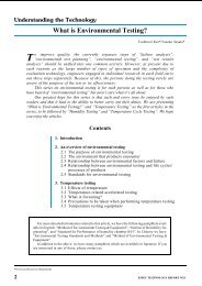
Introduction<br />
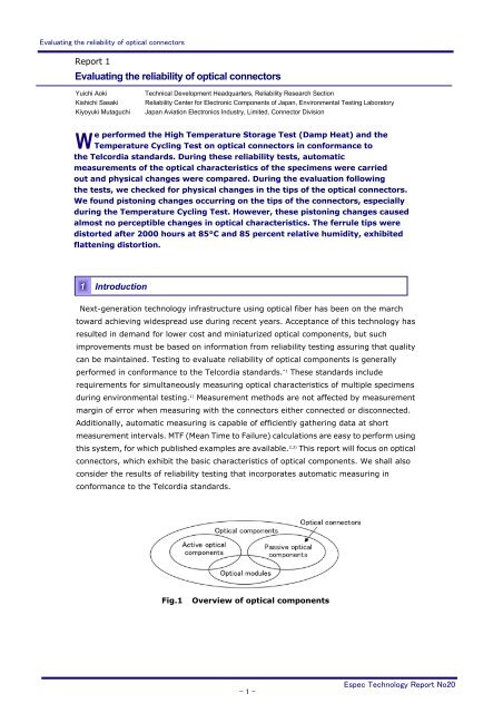
Next-generation technology infrastructure using <strong>optical</strong> fiber has been on <strong>the</strong> march<br />
toward achieving widespread use during recent years. Acceptance <strong>of</strong> this technology has<br />
resulted in demand for lower cost and miniaturized <strong>optical</strong> components, but such<br />
improvements must be based on information from <strong>reliability</strong> testing assuring that quality<br />
can be maintained. Testing to evaluate <strong>reliability</strong> <strong>of</strong> <strong>optical</strong> components is generally<br />
performed in conformance to <strong>the</strong> Telcordia standards. *1 These standards include<br />
requirements for simultaneously measuring <strong>optical</strong> characteristics <strong>of</strong> multiple specimens<br />
during environmental testing. 1) Measurement methods are not affected by measurement<br />
margin <strong>of</strong> error when measuring with <strong>the</strong> <strong>connectors</strong> ei<strong>the</strong>r connected or disconnected.<br />
Additionally, automatic measuring is capable <strong>of</strong> efficiently ga<strong>the</strong>ring data at short<br />
measurement intervals. MTF (Mean Time to Failure) calculations are easy to perform using<br />
this system, for which published examples are available. 2,3) This report will focus on <strong>optical</strong><br />
<strong>connectors</strong>, which exhibit <strong>the</strong> basic characteristics <strong>of</strong> <strong>optical</strong> components. We shall also<br />
consider <strong>the</strong> results <strong>of</strong> <strong>reliability</strong> testing that incorporates automatic measuring in<br />
conformance to <strong>the</strong> Telcordia standards.<br />
Fig.1 Overview <strong>of</strong> <strong>optical</strong> components<br />
- 1 -<br />
Espec Technology Report No20
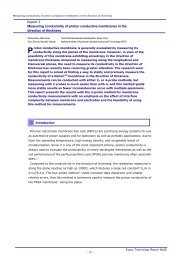
<strong>Evaluating</strong> <strong>the</strong> <strong>reliability</strong> <strong>of</strong> <strong>optical</strong> <strong>connectors</strong><br />
2<br />
The Telcordia standards that require simultaneously measuring <strong>optical</strong> characteristics <strong>of</strong><br />
multiple specimens are mainly concerned with passive <strong>optical</strong> components. In this report<br />
<strong>the</strong> term "passive <strong>optical</strong> components" refers to such items as fiber, <strong>connectors</strong>,<br />
switches, couplers, attenuators, and all types <strong>of</strong> filters. Table 1 shows <strong>reliability</strong> tests for<br />
typical <strong>optical</strong> components.<br />
3<br />
Test standards for passive <strong>optical</strong> components<br />
Table 1 Telcordia test standards<br />
Standard Title<br />
GR-326-CORE<br />
Generic Requirements for Single-Mode Optical Connectors and<br />
Jumper Assemblies<br />
GR-1209-CORE Generic Requirements for Passive Optical Components<br />
GR-1221-CORE<br />
Generic Reliability Assurance Requirements for Passive Optical<br />
Components<br />
Structure <strong>of</strong> <strong>optical</strong> <strong>connectors</strong> and factors affecting <strong>the</strong>ir <strong>reliability</strong><br />
Optical <strong>connectors</strong> are<br />
used to connect <strong>optical</strong><br />
fiber. Photo 1 shows<br />
some typical<br />
<strong>connectors</strong>. Fig.2<br />
shows <strong>the</strong> composition<br />
<strong>of</strong> <strong>the</strong> <strong>optical</strong><br />
<strong>connectors</strong> used in <strong>the</strong>se tests.<br />
The fiber is inserted into <strong>the</strong> housing, which is called a zirconia ferrule, and <strong>the</strong> fiber is<br />
held in place with a hardening epoxy adhesive. The adhesive used for <strong>the</strong> <strong>connectors</strong> is<br />
Epo-Tek353ND (Epoxy Technology, Inc.). The degradation <strong>of</strong> this adhesive is a crucial<br />
element leading to <strong>the</strong> loss <strong>of</strong> <strong>the</strong> <strong>reliability</strong> <strong>of</strong> <strong>the</strong> <strong>optical</strong> <strong>connectors</strong>. A major factor<br />
producing degradation is <strong>the</strong> absorption <strong>of</strong> humidity, which causes degradation to occur<br />
over time. 1~5) Photo 1 Optical <strong>connectors</strong><br />
The High Temperature Storage Test (Damp Heat) is used to evaluate<br />
humidity-induced degradation. As Fig.2 shows, adhesive degradation resulted in<br />
pistoning changes to <strong>the</strong> ferrule tip on <strong>the</strong> end <strong>of</strong> <strong>the</strong> <strong>optical</strong> <strong>connectors</strong>. A significant<br />
amount <strong>of</strong> pistoning causes such problems as an increase in air layers and an increase in<br />
leakage <strong>of</strong> insertion light. These problems result in an increase in <strong>optical</strong> loss.<br />
The Temperature Cycling Test was also run to evaluate <strong>the</strong> progression <strong>of</strong> cracking<br />
caused by micro-cracks in <strong>the</strong> fiber.<br />
- 2 -<br />
Espec Technology Report No20
<strong>Evaluating</strong> <strong>the</strong> <strong>reliability</strong> <strong>of</strong> <strong>optical</strong> <strong>connectors</strong><br />
Fig.2 Structure <strong>of</strong> <strong>optical</strong> <strong>connectors</strong> and factors affecting <strong>the</strong>ir <strong>reliability</strong><br />
4<br />
Environmental test system for <strong>optical</strong> components<br />
An environmental test system for <strong>optical</strong> components was developed to be used in this<br />
research for testing <strong>the</strong> <strong>reliability</strong> <strong>of</strong> passive <strong>optical</strong> components. Photo 2 shows <strong>the</strong><br />
system, and Fig.3 shows a block diagram <strong>of</strong> <strong>the</strong> system.<br />
This measurement system selects <strong>the</strong> light source wavelength using an <strong>optical</strong> switch<br />
selector, and is capable <strong>of</strong> measuring a maximum <strong>of</strong> 170 channels simultaneously for<br />
multiple specimens during environmental testing. This capability puts <strong>the</strong> system in<br />
conformance to <strong>the</strong> requirements <strong>of</strong> <strong>the</strong> Telcordia standards. The system is capable <strong>of</strong><br />
measuring insertion loss, *4 return loss, *5 and PDL (Polarization Dependent Loss). *6<br />
Photo 2 Environmental Test System<br />
- 3 -<br />
Espec Technology Report No20
<strong>Evaluating</strong> <strong>the</strong> <strong>reliability</strong> <strong>of</strong> <strong>optical</strong> <strong>connectors</strong><br />
5<br />
Test method<br />
Fig.3 System block diagram<br />
The High Temperature Storage Test (Damp Heat) and <strong>the</strong> Temperature Cycling Test<br />
were run using <strong>optical</strong> <strong>connectors</strong> as specimens. Table 2 shows <strong>the</strong> test conditions, and<br />
Table 3 shows <strong>the</strong> specimens. The test conditions complied with <strong>the</strong><br />
Telcordia-GR-1221-CORE standards. The specimens consisted <strong>of</strong> single mode *7 SC and FC<br />
<strong>connectors</strong>. As seen in Fig.4, <strong>the</strong> specimens were connected in groups <strong>of</strong> three <strong>optical</strong><br />
<strong>connectors</strong> with fiber and with <strong>the</strong> measurement points n = 5 (groups). The<br />
measurement system was used to measure insertion loss and return loss. Table 4 shows<br />
<strong>the</strong> measurement conditions.<br />
The test specimens were measured after each 1000 hours <strong>of</strong> <strong>the</strong> High Temperature<br />
Storage Test (Damp Heat) and after <strong>the</strong> completion <strong>of</strong> <strong>the</strong> Temperature Cycling Test. A<br />
Ferrule Tip Condition Surveyor (Direct Optical Research Company) was used to measure<br />
ferrule tip curvature radius, *8 eccentricity, *9 and pistoning. Failure was determined using<br />
<strong>the</strong> Telcordia-GR-1221-CORE evaluation standards shown in Table 5.<br />
The Temperature Cycling Test was not effective for determining degradation, since<br />
changes occurred in both insertion loss and return loss in <strong>the</strong> <strong>optical</strong> fiber temperature<br />
characteristics in this test. The PVC sheath *10 coating in particular exhibited major<br />
changes at low temperatures, and so <strong>the</strong> test was run using Hytrel ® core *11 , which<br />
exhibited minimal loss at low temperatures as seen in Fig.5.<br />
- 4 -<br />
Espec Technology Report No20
<strong>Evaluating</strong> <strong>the</strong> <strong>reliability</strong> <strong>of</strong> <strong>optical</strong> <strong>connectors</strong><br />
Table 2 Reliability test conditions<br />
Test items Test Conditions<br />
High<br />
Temperature<br />
Storage Test<br />
(Damp Heat)<br />
Temperature<br />
Cycling Test<br />
85°C, 85%rh,<br />
2000 h<br />
-40°C ←→ 85°C,<br />
1 hour each, 500<br />
cycles<br />
Fig.4 Test method<br />
Table 4 Measurement conditions<br />
Items Details<br />
Measurement items<br />
Insertion loss and<br />
return loss<br />
Light source<br />
wavelength<br />
1310 nm, 1550 nm<br />
Light source power 1 mW<br />
6<br />
Measurement<br />
intervals<br />
Test results<br />
Every 10 to 15 min.<br />
Specimens<br />
No. <strong>of</strong><br />
specimens<br />
Evaluation<br />
method<br />
- 5 -<br />
Table 3 Specimens<br />
FC <strong>connectors</strong>, SC <strong>connectors</strong><br />
(single mode)<br />
n = 5<br />
Insertion loss and return loss<br />
(<strong>optical</strong> component<br />
environmental test system)<br />
Tip condition measurement<br />
(pistoning, eccentricity, and<br />
curvature radius)<br />
Fig.5 Fiber temperature<br />
characteristics<br />
Table 5 Evaluation standards<br />
(from Telcordia GR-1221-CORE)<br />
Requirement Objective<br />
Insertion<br />
loss<br />
change<br />
0.3dB 0.2dB<br />
Return<br />
loss<br />
change<br />
6-1 Test results from <strong>the</strong> High Temperature Storage Test (Damp Heat)<br />
5dB 2dB<br />
Fig.6 shows <strong>the</strong> measurement results for <strong>the</strong> light source wavelength <strong>of</strong> 1310 nm for <strong>the</strong><br />
first 1000 hours <strong>of</strong> <strong>the</strong> 2000-hour High Temperature Storage Test (Damp Heat). After<br />
1000 hours and again after 2000 hours, we verified that fluctuation did not exceed any<br />
evaluation standards. In addition, identical trends were exhibited for both light source<br />
wavelengths, 1310 nm and 1550 nm. No major difference was seen between <strong>the</strong> FC<br />
<strong>connectors</strong> and <strong>the</strong> SC <strong>connectors</strong>.<br />
Espec Technology Report No20
<strong>Evaluating</strong> <strong>the</strong> <strong>reliability</strong> <strong>of</strong> <strong>optical</strong> <strong>connectors</strong><br />
Test time (h)<br />
(a) SC connector insertion loss<br />
Test time (h)<br />
(c) FC connector insertion loss<br />
- 6 -<br />
Test time (h)<br />
(b) SC connector return loss<br />
Test time (h)<br />
(d) FC connector return loss<br />
Fig.6 Results <strong>of</strong> <strong>the</strong> High Temperature Storage Test (Damp Heat)<br />
(light source wavelength: 1310 nm)<br />
6-2 Results <strong>of</strong> <strong>the</strong> Temperature Cycling Test<br />
Almost no differences were seen between <strong>the</strong> FC <strong>connectors</strong> and <strong>the</strong> SC <strong>connectors</strong> in<br />
<strong>the</strong> Temperature Cycling Test. Fig.7 shows partial measurement results for <strong>the</strong> SC<br />
<strong>connectors</strong>. Some insertion loss change and return loss change was seen following<br />
temperature changes in <strong>the</strong> temperature chamber during <strong>the</strong> Temperature Cycling Test,<br />
but <strong>the</strong>se changes did not exceed <strong>the</strong> evaluation standard limits. The changes included<br />
insertion loss occurring at low temperatures, but no major fluctuation was seen at high<br />
temperatures. Return loss, however, tended to increase at high temperatures. Looking at<br />
<strong>the</strong> return loss changes over <strong>the</strong> long term confirms that as soon as return loss increases,<br />
<strong>the</strong> fluctuation stabilizes. This is thought to indicate that return loss quality stabilizes due<br />
to <strong>the</strong> adhesion <strong>of</strong> <strong>the</strong> <strong>connectors</strong> over time.<br />
Espec Technology Report No20
<strong>Evaluating</strong> <strong>the</strong> <strong>reliability</strong> <strong>of</strong> <strong>optical</strong> <strong>connectors</strong><br />
(a) Insertion loss<br />
(b) Return loss<br />
Fig.7 Results <strong>of</strong> <strong>the</strong> Temperature Cycling Test<br />
(SC <strong>connectors</strong>; light source wavelength, 1310 nm)<br />
6-3 Pistoning measurement results<br />
Measurement results for <strong>the</strong> ferrule tip surfaces did not indicate major changes in<br />
eccentricity and curvature radius, but <strong>the</strong> measurements confirmed that changes<br />
occurred in pistoning compared to <strong>the</strong> initial values.<br />
Fig.8 shows pistoning measurements after 1000 and 2000 hours <strong>of</strong> <strong>the</strong> High<br />
Temperature Storage Test (Damp Heat), and after 500 cycles <strong>of</strong> <strong>the</strong> Temperature Cycling<br />
Test. This report represents <strong>the</strong> direction <strong>of</strong> pistoning as a negative value. In <strong>the</strong> IEC, <strong>the</strong><br />
standard for tolerance is recommended as -50 to 100 nm, and this level is exceeded, but<br />
<strong>the</strong> insertion loss and return loss measurements did not exhibit conspicuous fluctuation.<br />
On <strong>the</strong> o<strong>the</strong>r hand, <strong>optical</strong> <strong>connectors</strong> with powerful insertion light may be subject to<br />
influence by pistoning. Because <strong>of</strong> this, we face <strong>the</strong> challenge <strong>of</strong> investigating <strong>the</strong><br />
relationship between pistoning and <strong>optical</strong> characteristics in such areas as manufacturing<br />
conditions.<br />
In this research, more pistoning occurred in <strong>the</strong> Temperature Cycling Test than in <strong>the</strong><br />
High Temperature Storage Test (Damp Heat), regardless <strong>of</strong> whe<strong>the</strong>r <strong>the</strong> type <strong>of</strong> fiber<br />
coating included Hytrel ® core or <strong>the</strong> PVC sheath. The cause for <strong>the</strong> increased pistoning is<br />
thought to include stress in <strong>the</strong> direction <strong>of</strong> <strong>the</strong> pistoning from contraction and peeling <strong>of</strong><br />
<strong>the</strong> adhesive. This, in turn, is thought to be possibly caused by <strong>the</strong> effects <strong>of</strong> humidity and<br />
<strong>the</strong> re-hardening <strong>of</strong> <strong>the</strong> adhesive at <strong>the</strong> test temperature (85°C) for <strong>reliability</strong> testing.<br />
- 7 -<br />
Espec Technology Report No20
<strong>Evaluating</strong> <strong>the</strong> <strong>reliability</strong> <strong>of</strong> <strong>optical</strong> <strong>connectors</strong><br />
Test time (h)<br />
(85°C, 85%rh, PVC sheath coating)<br />
Test cycles<br />
(-40/85°C, 1 hour each, PVC sheath coating)<br />
Test cycles<br />
(-40/85°C, 1 hour each, Hytrel ® core)<br />
Fig.8 Changes in pistoning<br />
- 8 -<br />
Espec Technology Report No20
<strong>Evaluating</strong> <strong>the</strong> <strong>reliability</strong> <strong>of</strong> <strong>optical</strong> <strong>connectors</strong><br />
6-4 Observation <strong>of</strong> <strong>the</strong> tip shape<br />
Fig.9 shows <strong>the</strong> results <strong>of</strong> observations made on <strong>the</strong> shape <strong>of</strong> <strong>the</strong> ferrule tip before and<br />
after <strong>the</strong> High Temperature Storage Test (Damp Heat). After 2000 hours at 85°C and 85<br />
percent relative humidity, <strong>the</strong> surface <strong>of</strong> <strong>the</strong> ferrule tip showed signs <strong>of</strong> pitting and was<br />
rougher than before testing. This roughness did not appear on <strong>the</strong> surface <strong>of</strong> <strong>the</strong> tip after<br />
<strong>the</strong> Temperature Cycling Test, leading to <strong>the</strong> conclusion that <strong>the</strong> roughness was caused<br />
by humidity. Fig.10 shows a three-dimensional computer graphics rendition <strong>of</strong> <strong>the</strong> shape<br />
<strong>of</strong> <strong>the</strong> tip. After 2000 hours at 85°C and 85 percent relative humidity, <strong>the</strong> ferrule tip<br />
exhibited flattening distortion. However, pistoning measurements with <strong>the</strong> Ferrule Tip<br />
Condition Surveyor measured <strong>the</strong> position <strong>of</strong> <strong>the</strong> apex <strong>of</strong> <strong>the</strong> tip from <strong>the</strong> sphericity <strong>of</strong> <strong>the</strong><br />
ferrule tip, and, using that position as a standard, calculated <strong>the</strong> amount <strong>of</strong> pistoning.<br />
Accordingly, if <strong>the</strong> position <strong>of</strong> <strong>the</strong> tip section differs from <strong>the</strong>se measurements, <strong>the</strong><br />
amount <strong>of</strong> pistoning could be greater than that calculated.<br />
(a) Initial period<br />
(b) After testing<br />
Fig.9 Ferrule tip observation (85°C, 85%rh, 2000 h)<br />
(Initial period) (-40 /85°C, 500 cycles) (85°C, 85%rh, 2000 h)<br />
Fig.10 Three-dimensional shape <strong>of</strong> <strong>the</strong> ferrule tip<br />
- 9 -<br />
Espec Technology Report No20
<strong>Evaluating</strong> <strong>the</strong> <strong>reliability</strong> <strong>of</strong> <strong>optical</strong> <strong>connectors</strong><br />
7<br />
The <strong>optical</strong> characteristics <strong>of</strong> <strong>the</strong> <strong>optical</strong> <strong>connectors</strong> reviewed for this study were<br />
automatically measured during <strong>the</strong> High Temperature Storage Test (Damp Heat) (at<br />
85°C and 85 percent relative humidity for 1000 hours) and <strong>the</strong> Temperature Cycling Test<br />
(at 85°C / -40°C for 500 cycles <strong>of</strong> one hour each). We obtained <strong>the</strong> following results.<br />
(1)No changes occurred in <strong>optical</strong> characteristics, but pistoning increased in <strong>the</strong><br />
<strong>connectors</strong>.<br />
(2)Increased pistoning <strong>of</strong> <strong>the</strong> ferrule tips was observed in both <strong>the</strong> Temperature Cycling<br />
Test and <strong>the</strong> High Temperature Storage Test (Damp Heat), but <strong>the</strong> major changes<br />
occurred in <strong>the</strong> Temperature Cycling Test.<br />
(3)The post-test condition <strong>of</strong> <strong>the</strong> ferrule tips after testing at 85°C and 85 percent relative<br />
humidity for 2000 hours exhibited flattening distortion. This result could indicate that<br />
<strong>the</strong> actual pistoning was greater than <strong>the</strong> calculated amount.<br />
8<br />
Conclusion<br />
Topics for future discussion<br />
Many aspects <strong>of</strong> <strong>the</strong> relationship between pistoning and <strong>optical</strong> characteristics have yet<br />
to be confirmed, and topics such as manufacturing conditions also require research.<br />
[Terminology]<br />
*1.Telcordia<br />
The breakup <strong>of</strong> <strong>the</strong> American communications giant AT&T (Bell Telephone) created<br />
seven regional telephone providers (<strong>the</strong> so-called "Baby Bells") and established a<br />
research and development company initially called Bellcore. Later, when this<br />
subsidiary was sold to a company unrelated to <strong>the</strong> original Bell, <strong>the</strong> company became<br />
known as Telcordia Technologies. In <strong>the</strong> field <strong>of</strong> communications in <strong>the</strong> U.S., <strong>the</strong><br />
Telcordia standards are widely referenced as <strong>the</strong> baseline standards for this field.<br />
*2.SC <strong>connectors</strong>, and *3. FC <strong>connectors</strong><br />
Both <strong>of</strong> <strong>the</strong>se <strong>optical</strong> <strong>connectors</strong> are zirconia ferrule (refer to Fig.2 above) <strong>connectors</strong><br />
developed in Japan that are widely used throughout <strong>the</strong> world. The stationary part <strong>of</strong><br />
<strong>the</strong> SC connector is made <strong>of</strong> plastic, and can be connected by merely being pressed<br />
on. The stationary part <strong>of</strong> <strong>the</strong> FC connector, though, is made <strong>of</strong> metal and must be<br />
attached with screws.<br />
*4.Insertion loss<br />
The transmission loss occurring when light passes through <strong>the</strong> part. This value<br />
compares <strong>the</strong> insertion light with <strong>the</strong> outgoing light, and is expressed in decibels.<br />
*5.Return loss<br />
This value compares <strong>the</strong> insertion light power and <strong>the</strong> reflected light power <strong>of</strong> <strong>the</strong><br />
reflected light returning inside <strong>the</strong> part. This value is expressed in decibels.<br />
- 10 -<br />
Espec Technology Report No20
<strong>Evaluating</strong> <strong>the</strong> <strong>reliability</strong> <strong>of</strong> <strong>optical</strong> <strong>connectors</strong><br />
*6. PDL (Polarization Dependent Loss)<br />
The PDL value measures <strong>the</strong> change occurring in insertion loss caused by<br />
polarization. Polarization is a condition <strong>of</strong> deviation in <strong>the</strong> vibrational direction <strong>of</strong><br />
light.<br />
*7. Single mode<br />
Single mode is a condition which provides light with a single pathway <strong>of</strong> propagation.<br />
This mode contrasts with multi-mode, which consists <strong>of</strong> multiple pathways <strong>of</strong> light<br />
propagation. Due to <strong>the</strong> mode-dispersed loss occurring in multi-mode, single mode<br />
is used for long-distance transmission.<br />
*8. Curvature radius<br />
The length (in mm) <strong>of</strong> <strong>the</strong> radius <strong>of</strong> a circle from a circumference projected from a<br />
curved surface.<br />
*9. Eccentricity<br />
The length (in µm) <strong>of</strong> <strong>the</strong> deviation between <strong>the</strong> center <strong>of</strong> <strong>the</strong> ferrule and <strong>the</strong> center<br />
<strong>of</strong> <strong>the</strong> core <strong>of</strong> <strong>the</strong> <strong>optical</strong> fiber.<br />
*10.PVC sheath<br />
This polyvinyl chloride (PVC) sheath, referred to as <strong>optical</strong> fiber cable, has a<br />
protective fiber coating. This type <strong>of</strong> sheath is mainly used indoors.<br />
*11.Hytrel ® core<br />
Hytrel ® is a polyester elastomer made <strong>of</strong> <strong>the</strong>rmoplastic resin that was developed by<br />
<strong>the</strong> Dupont Corporation. This substance is an engineering plastic with superb<br />
features such as strength and heat characteristics. Hytrel ® core is a fiber optic<br />
stranded conductor coated with this elastomer.<br />
[Bibliography]<br />
1) "Generic Reliability Assurance Requirements for Passive Optical Components",<br />
Telcordia GR-1221-CORE Issue 2, 1999<br />
2) T. Tomasi, I. De Munari, V. Lista, L. Gherardi, A. Righetti, M. Villa: "Passive <strong>optical</strong><br />
components: from degradation data to <strong>reliability</strong> assessment-preliminary results",<br />
Microelectronics Reliability 42, p.1333-1338, 2002<br />
3) A. Piccirillo, G. Zaffiro, T. Tambosso, G. Gallo: "Reliability <strong>of</strong> Optical Branching<br />
Devices", IEEE (Institute <strong>of</strong> Electrical and Electronics Engineers), Journal <strong>of</strong> Selected<br />
Topics in Quantum Electronics, Vol.5 No.5, 1999<br />
4) F. Caloz, D. Ernst, P. Rossini, L. Gherardi, L. Grassi, J. Arnaud: "Reliability <strong>of</strong> <strong>optical</strong><br />
<strong>connectors</strong> - Humidity behavior <strong>of</strong> <strong>the</strong> adhesive", Microelectronics Reliability 42,<br />
p.1323-1328, 2002<br />
5) Tetso Kumazawa, Makoto Shimaoka, Kazuyuki Fukuda: "Moisture Absorbency <strong>of</strong><br />
Optical Components Resin Adhesive" Journal <strong>of</strong> Japan Institute <strong>of</strong> Electronics<br />
Packaging, Vol.4, No.7, p.621- 624, 2001<br />
- 11 -<br />
Espec Technology Report No20