download
download
download

Create successful ePaper yourself
Turn your PDF publications into a flip-book with our unique Google optimized e-Paper software.
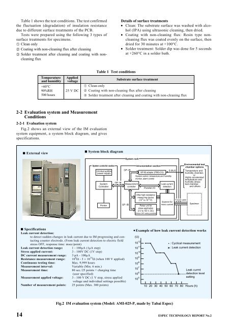
Table 1 shows the test conditions. The test confirmed<br />
the fluctuation (degradation) of insulation resistance<br />
due to different surface treatments of the PCB.<br />
Tests were prepared using the following 3 types of<br />
surface treatments for specimens.<br />
➀ Clean only<br />
➁ Coating with non-cleaning flux after cleaning<br />
➂ Solder treatment after cleaning and coating with noncleaning<br />
flux<br />
Temperature<br />
and humidity<br />
+60°C<br />
90%RH<br />
500 hours<br />
Applied<br />
voltage<br />
25 V DC<br />
2-2 Evaluation system and Measurement<br />
Conditions<br />
2-2-1 Evaluation system<br />
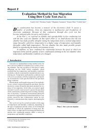
Fig.2 shows an external view of the IM evaluation<br />
system equipment, a system block diagram, and gives<br />
specifications.<br />
External view<br />
Table 1 Test conditions<br />
Details of surface treatments<br />
· Clean: The substrate surface was washed with alcohol<br />
(IPA) using ultrasonic cleaning, then dried.<br />
· Coating with non-cleaning flux: Resin type noncleaning<br />
flux was coated evenly on the surface, then<br />
dried for 30 minutes at +100°C.<br />
· Solder treatment: Solder dip was done for 5 seconds<br />
at +260°C in a solder bath.<br />
Substrate surface treatment<br />
➀ Clean-only<br />
➁ Coating with non-cleaning flux after cleaning<br />
➂ Solder treatment after cleaning and coating with non-cleaning flux<br />
System block diagram<br />
System controller section<br />
Uninterruptible<br />
power supply<br />
System<br />
Controller<br />
Printer<br />
GP-IB<br />
Specifications<br />
Leak current detection:<br />
to detect sudden changes in leak current due to IM progressing and contacting<br />
counter electrode. (From leak current detection to electric field<br />
stress OFF, response time: msec/point)<br />
Leak current detection range: 1 - 100mA (1mA step)<br />
Stress applied current: 3 - 100V DC (1V step)<br />
DC current measurement range: 3 pA - 100mA<br />
Resistance measurement range: 10 6 W - 3 ´ 10 13 W (when 100 V applied)<br />
Continuous testing time: Max. 9,999 hours<br />
Measurement interval: Variable (Min. 6 min.)<br />
Measurement time: 80 sec./25 points + charging time<br />
(user specified)<br />
Measurement applied voltage: 3 - 100 V DC (1 V step, stress applied<br />
voltage and individual settings possible)<br />
Number of measurement points: 25 points (Max. 300 points)<br />
System rack<br />
GP-IB<br />
Measurement<br />
controller<br />
GP-IB<br />
Intrumentation section<br />
E-BUS<br />
GP-IB adapter (PMS-CG)<br />
System control, temperature and humidity<br />
monitor, alarm control<br />
Parallel I/O<br />
Ultra high resistance<br />
measuring device<br />
6 13<br />
(10 to 10 )<br />
Power unit for<br />
stress application<br />
(3 V to 100 V, DC)<br />
(Stress OFF setting possible)<br />
Leak current<br />
detection<br />
Scanner for<br />
micro current<br />
Fig.2 IM evaluation system (Model: AMI-025-P, made by Tabai Espec)<br />
10 12<br />
10 11<br />
10 10<br />
10 9<br />
10 8<br />
10 7<br />
10 6<br />
10 5<br />
Triaxial cable<br />
Environmental test<br />
chamber options<br />
Temperature and<br />
humidity chamber,<br />
or<br />
Highly accelerated<br />
temperature and<br />
humidity stress<br />
test chamber,<br />
and others<br />
Specimen<br />
· Example of how leak current detection works<br />
: Cyclical measurement<br />
: Leak current detection<br />
Leak currnt<br />
detection level<br />
setting<br />
10 20 30 40 50 60 70 80 Hours (h)<br />
14 ESPEC TECHNOLOGY REPORT No.2