Hotsy 558-559_0111 - ETS Company Pressure Washers and More
Hotsy 558-559_0111 - ETS Company Pressure Washers and More
Hotsy 558-559_0111 - ETS Company Pressure Washers and More

You also want an ePaper? Increase the reach of your titles
YUMPU automatically turns print PDFs into web optimized ePapers that Google loves.
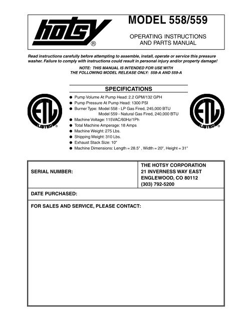
THE HOTSY CORPORATION<br />
SERIAL NUMBER: 21 INVERNESS WAY EAST<br />
ENGLEWOOD, CO 80112<br />
(303) 792-5200<br />
DATE PURCHASED:<br />
FOR SALES AND SERVICE, PLEASE CONTACT:<br />
OPERATING INSTRUCTIONS<br />
AND PARTS MANUAL<br />
Read instructions carefully before attempting to assemble, install, operate or service this pressure<br />
washer. Failure to comply with instructions could result in personal injury <strong>and</strong>/or property damage!<br />
®<br />
MODEL <strong>558</strong>/<strong>559</strong><br />
NOTE: THIS MANUAL IS INTENDED FOR USE WITH<br />
THE FOLLOWING MODEL RELEASE ONLY: <strong>558</strong>-A AND <strong>559</strong>-A<br />
SPECIFICATIONS<br />
● Pump Volume At Pump Head: 2.2 GPM/132 GPH<br />
● Pump <strong>Pressure</strong> At Pump Head: 1300 PSI<br />
● Burner Type: Model <strong>558</strong> - LP Gas Fired, 245,000 BTU<br />
Model <strong>559</strong> - Natural Gas Fired, 240,000 BTU<br />
● Machine Voltage: 115VAC/60Hz/1Ph<br />
● Total Machine Amperage: 18 Amps<br />
● Machine Weight: 275 Lbs.<br />
● Shipping Weight: 310 Lbs.<br />
● Exhaust Stack Size: 10"<br />
● Machine Dimensions: Length = 28.5" , Width = 20", Height = 31"<br />
®
IMPORTANT SAFETY INSTRUCTIONS<br />
Read <strong>and</strong> observe to prevent severe personal injury or property damage.<br />
WARNING - When using this product basic precautions<br />
should always be followed, including the following:<br />
● Read all instructions before using this product.<br />
● Know how to stop the product <strong>and</strong> bleed all pressures quickly.<br />
Be thoroughly familiar with the controls.<br />
● To reduce the risk of injury, close supervision is necessary<br />
when this product is used near children.<br />
● Do not operate this product when fatigued or under the<br />
influence of alcohol or drugs.<br />
● STAY ALERT - watch what you are doing.<br />
● Keep operating area clear of all persons.<br />
● If equipped with a GFCI, test the GFCI using the reset <strong>and</strong><br />
test procedures provided on the GFCI device. The GFCI must<br />
be tested with every use.<br />
● Follow the maintenance instructions specified in the manual.<br />
WARNING - RISK OF EXPLOSION<br />
● Do not spray flammable liquids or operate machine in areas<br />
where flammable vapors are present. Operate only where open<br />
flame or torch is permitted.<br />
WARNING - RISK OF ELECTROCUTION OR INJURY<br />
● Disconnect power supply before performing any maintenance.<br />
Failure to do so could result in severe shock or unexpected<br />
machine operation causing bodily injury.<br />
● Make sure all switches <strong>and</strong> controls are in the OFF position<br />
prior to connecting electrical supply.<br />
● Do not st<strong>and</strong> in water while connecting <strong>and</strong> disconnecting electrical<br />
supply.<br />
● Keep all electrical components <strong>and</strong> connections dry <strong>and</strong> off<br />
ground.<br />
WARNING - RISK OF INJECTION OR SEVERE INJURY<br />
● Keep clear of nozzle. Do not direct discharge stream at<br />
persons. This machine is to be used only by qualified<br />
operators.<br />
AVERTISSEMENT:RISQUE D’INJECTION ET DE BLESSURES<br />
GRAVES. SE TENIR À L’ÉCART DU JET. NE PAS DIRIGER LE JET DE<br />
SORTIE VERS D’AUTRES PERSONNES. CONFIER L’UTILISATION DE<br />
CE MATÉRIEL À UN OPÉRATEUR QUALIFIÉ.<br />
● Use with eye, ear, h<strong>and</strong>, foot <strong>and</strong> skin protection at all times.<br />
● Before changing or adjusting nozzle, engage manual<br />
trigger gun lock.<br />
CAUTION - RISK OF INJURY<br />
● To reduce the RISK OF INJURY, read Operating Instructions<br />
carefully before using.<br />
● Trigger gun kicks back, hold with both h<strong>and</strong>s.<br />
● Do not overreach or st<strong>and</strong> on unstable support. Keep good<br />
footing <strong>and</strong> balance at all times.<br />
● To prevent personal injuries due to falls, the use of auxiliary<br />
safety equipment may be required.<br />
● Hot discharge fluid. DO NOT touch or direct spray at persons.<br />
● Hot surfaces - Use only designed gripping areas of lance (w<strong>and</strong><br />
or trigger gun) <strong>and</strong> avoid contact with non-insulated areas of<br />
machine to prevent the possibility of severe burns.<br />
● Check hoses, fittings, w<strong>and</strong>, trigger gun <strong>and</strong> fuel connections<br />
daily for signs of wear, cracks <strong>and</strong> looseness, <strong>and</strong> replace as<br />
required.<br />
● Do not block or tie trigger gun in the open position.<br />
● Cleaning area should be provided with adequate drainage.<br />
● Do not allow machine to run unattended.<br />
SAVE THESE INSTRUCTIONS<br />
CAUTION - RISK OF ASPHYXIATION<br />
● Do not run machine indoors or in an enclosed area without<br />
the required venting, as exhaust fumes may be hazardous to<br />
your health.<br />
CAUTION<br />
● The pilot on this machine lights automatically. Never attempt<br />
to light the pilot or burner manually.<br />
● Before operating this machine, smell around the area for gas.<br />
Be sure to smell next to the floor because some gases are<br />
heavier than air <strong>and</strong> will settle to the floor. If you smell gas,<br />
follow the procedure below:<br />
1. Do not try to operate this machine or any other appliance.<br />
2. Do not operate any electrical switches, <strong>and</strong> do not use the<br />
phone in your building.<br />
3. Immediately call your gas supplier from a phone off the premises.<br />
Follow the gas supplier’s instructions.<br />
4. If you cannot reach your gas supplier, call the fire department.<br />
AVANT DE METTRE EN MARCHE CETTE MACHINE, VÉRIFIEZ QU’IL<br />
N’Y A PAS DE FUITE DE GAZ À PROXIMITÉ. SENTEZ AU NIVEAU<br />
DU SOL PARCE QUE CERTAINS GAZ SONT PLUS LOURDS ET<br />
STAGNENT AU SOL. SI VOUS SENTEZ LE GAZ, SUIVEZ LES IN-<br />
STRUCTIONS SUIVANTES:<br />
1. NE PAS METTRE EN MARCHE CETTE MACHINE OU AUCUNE AU-<br />
TRE MACHINE.<br />
2. NE PAS ALLUMER LA LUMIÈRE OU UTILISER LE TÉLÉPHONE<br />
DANS VOTRE BÂTIMENT.<br />
3. APPELER IMMÉDIATEMENT LE SERVICE DE GAZ DEPUIS UN<br />
TÉLÉPHONE HORS DE VOTRE BÂTIMENT. SUIVRE LES INSTRUC-<br />
TIONS DONNÉES PAR VOTRE SERVICE DE GAZ.<br />
4. SI VOUS NE POUVEZ PAS JOINDRE VOTRE SERVICE DE GAZ,<br />
APPELEZ LES POMPIERS.<br />
● When applying detergents follow the safety rules on the detergent<br />
label.<br />
● Use only approved detergent from a covered, D.O.T. approved,<br />
container.<br />
● Troubleshoot machine before pressing any reset buttons. See<br />
Troubleshooting Guide.<br />
● Failure to operate in accordance with operating manual may<br />
be dangerous <strong>and</strong> will void warranty.<br />
IMPORTANT<br />
● This machine is not to be connected to type B gas vent.<br />
NE PAS RACCORDER CET APPAREIL À UN TUYAU D’ÉVACUATION<br />
DE GAZ DU TYPE B.<br />
● A draft diverter shall be installed.<br />
INSTALLER UNE HOTTE DE TIRAGE.<br />
● This machine must be electrically grounded.<br />
LA MACHINE DOIT ÊTRE MISE À LA TERRE.<br />
● Connect this machine to an individual branch circuit only.<br />
● If this machine is connected to a circuit protected by fuses,<br />
use time delay fuses.<br />
● Consult manual <strong>and</strong> local building codes for installation requirements.<br />
Licensed contractor may be required.<br />
● Contact an authorized service technician for repairs. Unauthorized<br />
machine modification or use of non-approved replacement<br />
parts may cause personal injury <strong>and</strong>/or property<br />
damage <strong>and</strong> will void the manufacturer warranty.<br />
● This machine has been provided with Warning <strong>and</strong> Instruction<br />
decals for the safety of the operator. If these decals are<br />
removed or become damaged they should be replaced.<br />
Page 2 <strong>Hotsy</strong> <strong>558</strong>-<strong>559</strong>
CONTROL BOX<br />
PRESSURE<br />
HOSE<br />
ATTACHMENT<br />
DETERGENTS<br />
PILOT INDICATOR LIGHT<br />
Figure 1 - Machine Component Layout<br />
<strong>Hotsy</strong> <strong>558</strong>-<strong>559</strong><br />
BURNER SWITCH<br />
MOTOR RESET SWITCH<br />
PUMP SWITCH<br />
UNLOADER VALVE<br />
MOTOR<br />
COIL DRAIN PLUG<br />
GAS BURNER<br />
ADJUSTABLE<br />
PRESSURE NOZZLE<br />
CAUTION<br />
CAUTION<br />
WARNING<br />
WARNING<br />
HOSE HANGER<br />
OPERATING INSTRUCTIONS<br />
OPERATING<br />
INSTRUCTIONS<br />
GAS ON/OFF KNOB<br />
PILOT<br />
ON<br />
RESET<br />
PUMP OFF<br />
TEMPERATURE<br />
BURNER<br />
WAND TRIGGER GUN<br />
WAND<br />
HOLDER<br />
PILOT IGNITOR<br />
BUTTON<br />
BURNER EXHAUST VENT<br />
THERMOSTAT<br />
RELIEF VALVE<br />
PUMP<br />
DETERGENT INJECTOR VALVE<br />
GARDEN HOSE CONNECTOR<br />
DETERGENT LINE<br />
GAS INLET<br />
GAS VALVE<br />
PRESSURE<br />
HOSE<br />
GFCI POWER<br />
CORD<br />
(GROUND<br />
FAULT CIRCUIT<br />
INTERRUPTER)<br />
Page 3
Unpacking<br />
ASSEMBLY<br />
Unpack carefully. Wear safety glasses or goggles while<br />
unpacking, assembling or operating pressure washer. If<br />
there are missing components or hidden damage<br />
immediately contact distributor or carrier concerning<br />
discrepancies.<br />
1. Cut strapping b<strong>and</strong> from pressure washer <strong>and</strong> pallet.<br />
2. Remove pressure washer from pallet.<br />
Parts Included<br />
• <strong>Pressure</strong> Washer<br />
<strong>Pressure</strong> Hose<br />
Hose Hanger<br />
W<strong>and</strong><br />
Parts Bag Containing:<br />
■ Adjustable <strong>Pressure</strong> Nozzle<br />
■ Garden Hose Connector<br />
■ Quick Disconnect<br />
■ Trigger Gun<br />
■ Garden Hose Connector Spring<br />
■ Quick Disconnect Plug<br />
Operating Instructions <strong>and</strong> Parts Manual<br />
Tools Required<br />
10" Adjustable Crescent Wrench (2 ea.)<br />
1/2" Allen Wrench<br />
Small Flat Head Screwdriver<br />
Hose Hanger<br />
1. Install the hose hanger as shown in Figure 2.<br />
HOSE HANGER<br />
POCKET ON<br />
COIL TANK<br />
Figure 2 - Hose Hanger Installation<br />
<strong>Pressure</strong> Hose, Trigger Gun <strong>and</strong> W<strong>and</strong><br />
1. When assembling, use teflon tape on all plumbing<br />
connections to prevent leakage.<br />
2. Install the pressure hose on the pressure washer as<br />
shown in Figure 3.<br />
Figure 3 - Installing <strong>Pressure</strong> Hose<br />
3. Assemble w<strong>and</strong> components as shown in Figure 4.<br />
Connect pressure hose to trigger gun.<br />
PRESSURE HOSE<br />
RELIEF VALVE<br />
QUICK DISCONNECT<br />
PLUG<br />
QUICK<br />
DISCONNECT<br />
TRIGGER GUN<br />
Figure 4 - Trigger Gun/W<strong>and</strong> Assembly<br />
NOTE: The pressure nozzle is not to be installed at<br />
this time.<br />
4. Make sure that all plumbing connections are tight.<br />
Garden Hose Connector<br />
PRESSURE HOSE<br />
1. When assembling, use teflon tape on all plumbing<br />
connections to prevent leakage.<br />
2. Locate the garden hose connector <strong>and</strong> garden hose<br />
connector spring from the parts bag.<br />
3. Assemble the spring <strong>and</strong> connector to the detergent<br />
injector as shown in Figure 11.<br />
4. Make sure that all plumbing connections are tight.<br />
Page 4 <strong>Hotsy</strong> <strong>558</strong>-<strong>559</strong><br />
WAND
Getting Started<br />
<strong>Hotsy</strong> <strong>558</strong>-<strong>559</strong><br />
INSTALLATION<br />
IMPORTANT: Proper initial installation of equipment<br />
will assure more satisfactory performance, longer<br />
service life <strong>and</strong> lower maintenance cost.<br />
IMPORTANT: The use of a backflow preventer on the<br />
water supply hose is recommended <strong>and</strong> may be<br />
required by local codes.<br />
The pressure washer should be run on a level surface<br />
where it is not readily influenced by outside sources<br />
such as strong winds, freezing temperatures, rain, etc.<br />
The pressure washer should be located to assure easy<br />
access for filling of fluids, adjustments <strong>and</strong> maintenance.<br />
Normal precautions should be taken by the operator to<br />
prevent moisture from reaching the pressure washer. It<br />
is recommended that a partition be made between the<br />
wash area <strong>and</strong> the pressure washer to prevent direct spray<br />
from the w<strong>and</strong> coming in contact with the pressure washer.<br />
Moisture reaching the equipment will reduce the pressure<br />
washer’s service life. All installations should comply with<br />
the local codes covering such installations.<br />
Venting<br />
WARNING - RISK OF EXPLOSION: Do not spray flammable<br />
liquids or operate machine in areas where flammable<br />
vapors are present. Operate only where open<br />
flame or torch is permitted.<br />
CAUTION - RISK OF ASPHYXIATION: Do not run<br />
machine indoors or in an enclosed area without the<br />
required venting, as exhaust fumes may be hazardous<br />
to your health.<br />
CAUTION: Some gases are heavier than air <strong>and</strong> will<br />
spill out on the floor in the 2 to 3 minutes required for<br />
the safety pilot valve to close off gas supply. Therefore,<br />
always provide adequate space <strong>and</strong> ventilation<br />
around these units.<br />
CAUTION: All venting must be in accordance with<br />
applicable federal <strong>and</strong> state laws, <strong>and</strong> local ordinances.<br />
Consult local heating contractors.<br />
IMPORTANT: This machine is not to be connected to<br />
a type B gas vent. NE PAS RACCORDER CET<br />
APPAREIL À UN TUYAU D’ÉVACUATION DE GAZ DU<br />
TYPE B.<br />
IMPORTANT: A draft diverter shall be installed.<br />
INSTALLER UNE HOTTE DE TIRAGE.<br />
If the pressure washer is to be used in an enclosed area,<br />
a flue must be installed to vent burner exhaust to the<br />
outside atmosphere. Exhaust gases should not be vented<br />
into a wall, a ceiling, or a concealed space of a building.<br />
Be sure the flue is the same size as the burner exhaust<br />
vent on the pressure washer. Poor draft will cause the<br />
pressure washer to soot <strong>and</strong> not operate properly. When<br />
selecting the location for installation, beware of poorly<br />
ventilated locations or areas where exhaust fans may<br />
cause an insufficient supply of oxygen. Proper combustion<br />
can only be obtained when there is a sufficient supply of<br />
oxygen available for the amount of fuel being burned. If it<br />
is necessary to install the machine in a poorly ventilated<br />
area, outside fresh air may have to be piped to the burner<br />
<strong>and</strong> a fan installed to bring sufficient air into the machine.<br />
Locate the pressure washer so that the flue will be as<br />
straight as possible <strong>and</strong> protrude through the roof at a<br />
proper height <strong>and</strong> location to provide adequate draft. This<br />
gas fired pressure washer must have a draft diverter<br />
installed in the flue (available from most heating<br />
contractors). A draft diverter will permit proper upward<br />
flow of exhaust flue gases.<br />
Water Supply<br />
Connect water supply hose to the garden hose connector.<br />
See Figure 1 for location. The water faucet <strong>and</strong> supply<br />
hose must be capable of providing a minimum of 2.2<br />
gallons per minute (GPM).<br />
Fuel Supply<br />
CAUTION: Have a qualified gas serviceman install <strong>and</strong><br />
service your equipment.<br />
WARNING: Gas line supply pressure must not exceed<br />
14" water column (.50 PSI).<br />
IMPORTANT: Gas line must be provided with a shut<br />
off valve.<br />
IMPORTANT: The gas supply must be able to supply<br />
a minimum of 245,000 BTU/HR at the machines rated<br />
manifold pressure.<br />
Consult building codes for installation requirements.<br />
For proper <strong>and</strong> safe machine operation, we recommend<br />
that a licensed contractor be consulted for machine<br />
installation.<br />
Page 5
LP Vapor Fuel<br />
The model <strong>558</strong> has been factory built to use LP vapor<br />
fuel. DO NOT USE LIQUID FUEL.<br />
Have a qualified gas serviceman install the LP vapor fuel<br />
supply line to the machine. See Figure 5 for location of<br />
gas inlet.<br />
Natural Gas Fuel<br />
The model <strong>559</strong> has been factory built to use natural gas<br />
fuel.<br />
Have a qualified gas serviceman install the natural gas<br />
fuel supply line to the machine. See Figure 5 for location<br />
of gas inlet.<br />
Gas Regulator<br />
It is very important that the incoming gas pressure be<br />
between 12.0-14.0 Water Column Inches (.43-.50 PSI).<br />
If your fuel supply does not produce the correct pressure<br />
range contact your local <strong>Hotsy</strong> Service Representative.<br />
The gas pressure coming out of the regulator <strong>and</strong> going<br />
to the burner ring has been factory set. You should not<br />
readjust the burner ring gas pressure. If you replace your<br />
gas valve, you will need to adjust the new valve. Refer<br />
to your machine’s specification plate for the correct<br />
pressure setting. Follow the installation <strong>and</strong> adjustment<br />
instructions provided with your replacement valve.<br />
Electrical<br />
WARNING: Make sure all switches <strong>and</strong> controls<br />
are in the OFF position prior to connecting electrical<br />
supply.<br />
GAS INLET<br />
GAUGE<br />
ON/OFF KNOB<br />
Figure 5 - Gas Valve Components<br />
GAS TEE<br />
MAIN ADJUSTMENT<br />
WARNING: DO NOT st<strong>and</strong> in water while connecting<br />
<strong>and</strong> disconnecting electrical supply.<br />
WARNING: Always disconnect power before servicing<br />
your pressure washer.<br />
IMPORTANT: Consult local building codes for exact<br />
electrical requirements. Licensed contractors may be<br />
required.<br />
IMPORTANT: All wiring must be of proper voltage <strong>and</strong><br />
amperage rating <strong>and</strong> conform to applicable codes.<br />
IMPORTANT: This machine must be electrically<br />
grounded. LA MACHINE DOIT ÊTRE MISE À LA TERRE.<br />
Grounding Instructions: Make sure all switches <strong>and</strong><br />
controls are in the OFF position prior to connecting<br />
electrical supply. Do not st<strong>and</strong> in water while connecting<br />
<strong>and</strong> disconnecting electrical supply. If it should malfunction<br />
or break down, grounding provides a path of least<br />
resistance for electric current to reduce the risk of electric<br />
shock. The product must be connected to an appropriate<br />
power source that is properly installed <strong>and</strong> grounded in<br />
accordance with all local codes <strong>and</strong> ordinances.<br />
DANGER: Improper connection of the equipment<br />
grounding conductor can result in a risk of electrocution.<br />
Check with a qualified electrician or service<br />
personnel if you are in doubt as to whether the outlet<br />
is properly grounded. DO NOT modify the plug provided<br />
with the product - if it will not fit the outlet, have<br />
a proper outlet installed by a qualified electrician. DO<br />
NOT use any type of adaptor with this product.<br />
WARNING: To reduce the risk of electrocution, keep<br />
all connections dry <strong>and</strong> off the ground. DO NOT touch<br />
plug with wet h<strong>and</strong>s.<br />
SIDE VIEW<br />
TO BURNER RING<br />
FINE ADJUSTMENT<br />
GAS VALVE<br />
PRESSURE TAP PORT<br />
SELECTION BUTTON (OUT FOR NATURAL GAS)<br />
Page 6 <strong>Hotsy</strong> <strong>558</strong>-<strong>559</strong>
Before Starting<br />
<strong>Hotsy</strong> <strong>558</strong>-<strong>559</strong><br />
OPERATION<br />
1. Read all manuals provided with this pressure washer.<br />
Become familiar with location <strong>and</strong> function of all<br />
operating <strong>and</strong> safety controls.<br />
Grounding Instructions: This product must be electrically<br />
grounded. If it would malfunction or break down, grounding<br />
provides a path of least resistance for electric current to<br />
reduce the risk of electric shock. This machine must be<br />
wired into an appropriate outlet that is properly installed<br />
<strong>and</strong> grounded in accordance with all local codes <strong>and</strong><br />
ordinances.<br />
DANGER: Improper wiring connections of the equipment<br />
can result in a risk of electrocution. Check with<br />
a qualified electrician or service personnel if you are<br />
in doubt as to whether the outlet is properly grounded.<br />
WARNING: Make sure all switches <strong>and</strong> controls are<br />
in the OFF position prior to plugging in electrical cord.<br />
WARNING: DO NOT st<strong>and</strong> in water while plugging or<br />
unplugging electrical cord.<br />
CAUTION: This pressure washer is equipped with a<br />
UL approved ground fault circuit interrupter (GFCI)<br />
power cord. Use UL grounded type receptacles of<br />
proper voltage <strong>and</strong> amperage ratings. Where a properly<br />
grounded receptacle is not available, it is the<br />
personal responsibility of the owner to have one<br />
installed. Always disconnect power before servicing<br />
your pressure washer.<br />
CAUTION: This machine is equipped with a 35 foot<br />
long power cord protected by a ground fault circuit<br />
interrupter (GFCI). DO NOT use extension cords due<br />
to possible severe electrical shock <strong>and</strong>/or damage to<br />
the machine.<br />
2. Connect electrical cord to an overload protected<br />
115VAC/60Hz/1Ph grounded circuit, minimum 18 ampere<br />
rated. Test the GFCI using the reset <strong>and</strong> test<br />
procedure located on the GFCI device. Do not use<br />
machine if GFCI fails test. The GFCI must be reset<br />
<strong>and</strong> tested with every use.<br />
WARNING: Check hoses, fittings, w<strong>and</strong>, trigger gun<br />
<strong>and</strong> fuel connections daily for signs of wear, cracks<br />
<strong>and</strong> looseness, <strong>and</strong> replace as required.<br />
3. Connect water supply hose to the garden hose connector,<br />
see Figure 1 for location. The water faucet<br />
<strong>and</strong> supply hose must be capable of providing a minimum<br />
of 2.2 gallons per minute (GPM).<br />
4. This machine was factory built for either LP vapor fuel<br />
or Natural Gas. See instructions under Fuel Supply.<br />
5. Check pump oil level.<br />
6. If detergents are to be used, only use detergents<br />
intended for pressure washers. Follow instructions<br />
on the detergent container.<br />
IMPORTANT: Before installing pressure nozzle on initial<br />
start-up, turn on the water supply, start the pump<br />
by pressing the pump ON switch, <strong>and</strong> hold the trigger<br />
gun trigger open until water appears at the end of<br />
the w<strong>and</strong>. Allow water to run from the end of the w<strong>and</strong><br />
until clear to prevent the nozzle from clogging.<br />
IMPORTANT: If the pressure washer has not been<br />
used for an extended period of time, remove the pressure<br />
nozzle from the end of the trigger gun <strong>and</strong> turn<br />
on water supply, <strong>and</strong> start the pump by pressing the<br />
pump ON switch. Hold the trigger gun trigger open<br />
<strong>and</strong> allow water to run from the end of the w<strong>and</strong> until<br />
clear.<br />
7. Install the adjustable pressure nozzle on end of w<strong>and</strong>,<br />
refer to Figure 6.<br />
ADJUSTABLE<br />
PRESSURE NOZZLE<br />
MANUAL TRIGGER LOCK<br />
Figure 6 - Nozzle Installation/Manual Trigger Lock<br />
NOTE: To prevent damage to the pressure nozzle, only<br />
place the wrench on hex area when tightening.<br />
IMPORTANT: The trigger gun provided with this pressure<br />
washer is equipped with a manual trigger lock<br />
to prevent accidental operation of the trigger gun,<br />
refer to Figure 6. The trigger lock should be used<br />
whenever the trigger gun is not in use.<br />
IMPORTANT: Pump may require priming the first time<br />
the pressure washer is run. See step 8.<br />
8. If you are running the machine for the first time, or<br />
the machine has been sitting for a period of time, the<br />
pump may require priming. To prime the pump, run<br />
pressure washer with only the pump switch on.<br />
IMPORTANT: On initial start-up or if maintenance has<br />
been performed on the burner assembly, it will be necessary<br />
to bleed the air from the gas line before the<br />
pilot will light.<br />
9. If you are running the machine for the first time or<br />
have performed maintenance to the burner assembly,<br />
there will be air in the gas line. To bleed out the air<br />
from the gas line, run pressure washer with pump<br />
<strong>and</strong> burner switches ON <strong>and</strong> thermostat on highest<br />
setting. Squeeze the trigger of the trigger gun for 15<br />
seconds. If the burner has not ignited, release the<br />
trigger for 5 seconds then squeeze for 15 seconds. If<br />
the burner has not ignited after 10 tries, see the<br />
Troubleshooting Guide in this manual.<br />
CAUTION: Have a qualified gas service technician<br />
install <strong>and</strong> service your equipment.<br />
DANGER: Never expose a spark or flame where there<br />
may be unburned gas present.<br />
Page 7
DANGER: Some gases are heavier than air <strong>and</strong> will<br />
spill out on the floor in the 2 to 3 minutes required for<br />
the safety pilot valve to close off gas supply. Therefore,<br />
always provide adequate space <strong>and</strong> ventilation<br />
around these units.<br />
To Start<br />
WARNING: Risk of injection or severe injury - Keep<br />
clear of nozzle - DO NOT direct discharge stream at<br />
persons - This machine is to be used only by qualified<br />
operators.<br />
AVERTISSEMENT: RISQUE D’INJECTION ET DE<br />
BLESSURES GRAVES. SE TENIR À L’ÉCART DU JET.<br />
NE PAS DIRIGER LE JET DE SORTIE VERS D’AUTRES<br />
PERSONNES. CONFIER L’UTILISATION DE CE<br />
MATÉRIEL À UN OPÉRATEUR QUALIFIÉ.<br />
WARNING: Wear eye, ear, h<strong>and</strong>, foot, <strong>and</strong> skin protection<br />
at all times while operating pressure washer.<br />
IMPORTANT: The water must be turned on before starting.<br />
Running the pump dry will cause damage <strong>and</strong><br />
void warranty.<br />
IMPORTANT: Do not allow the machine to run in<br />
bypass for more than 10 minutes at any one time or<br />
damage to pump may occur.<br />
1. Connect electrical cord <strong>and</strong> test GFCI device.<br />
2. Turn water on.<br />
NOTE: The pilot indicator light on the control box will<br />
ONLY indicate the presence of the pilot while the<br />
machine is in operation. This light will be off when<br />
the machine is not running.<br />
NOTE: The pilot may require repeated attempts to<br />
ignite following initial installation or replacement of<br />
the natural gas supply. The delay in ignition is due to<br />
trapped air in the gas supply/pilot line.<br />
3. Open gas supply valve.<br />
4. Turn the gas valve ON/OFF knob to pilot position.<br />
5. Fully depress gas ON/OFF knob <strong>and</strong> hold in. Immediately<br />
push the ignitor button down <strong>and</strong> repeat until<br />
the pilot ignites. If the pilot fails to ignite within 30<br />
seconds, release the gas control knob, depress<br />
slightly <strong>and</strong> turn to the OFF position. Wait 15 minutes<br />
<strong>and</strong> repeat steps 4 <strong>and</strong> 5.<br />
6. Once pilot has ignited, continue to depress the gas<br />
control knob for an additional 60 seconds before<br />
releasing.<br />
7. Turn gas control knob to the ON position.<br />
8. Hold w<strong>and</strong> firmly, release trigger of trigger gun <strong>and</strong><br />
turn pump switch ON. Squeeze trigger of trigger gun<br />
<strong>and</strong> allow air to purge from system.<br />
9. If HOT water is desired, adjust the thermostat to the<br />
proper temperature <strong>and</strong> turn burner switch ON.<br />
Squeeze trigger of trigger gun. The pilot will automatically<br />
light, quickly followed by the firing of the burner<br />
ring. When the trigger of the trigger gun is released<br />
or when the thermostat temperature setting is<br />
reached, the burner will automatically turn off.<br />
IMPORTANT: If ignition or flame failure is experienced,<br />
discontinue use of pressure washer at once. Turn off<br />
burner <strong>and</strong> shut off fuel supply. Have cause of failure<br />
corrected by an authorized service technician before<br />
use of pressure washer is continued.<br />
To Clean<br />
WARNING: Risk of injection or severe injury - Keep<br />
clear of nozzle - DO NOT direct discharge stream at<br />
persons - This machine is to be used only by qualified<br />
operators.<br />
AVERTISSEMENT: RISQUE D’INJECTION ET DE<br />
BLESSURES GRAVES. SE TENIR À L’ÉCART DU JET.<br />
NE PAS DIRIGER LE JET DE SORTIE VERS D’AUTRES<br />
PERSONNES. CONFIER L’UTILISATION DE CE<br />
MATÉRIEL À UN OPÉRATEUR QUALIFIÉ.<br />
The detergent injector valve (Figure 11) operates by<br />
reducing the volume of water, thus a vacuum is achieved<br />
<strong>and</strong> detergent is drawn into the system. DO NOT reduce<br />
the water inlet flow so much that the pump cavitates<br />
because of water starvation. Operating a pump with<br />
insufficient water will damage the pump seals.<br />
1. Insert detergent line <strong>and</strong> screen into container of<br />
detergent.<br />
2. Completely open detergent control knob located on<br />
the side of the detergent injector valve.<br />
3. Start the detergent suction by rotating the water<br />
adjustment knob of the detergent injector valve. Turning<br />
the knob counterclockwise will pull detergent into<br />
the system. The flow may be observed through the<br />
clear detergent line. Secure the knob position with<br />
the knurled nut.<br />
4. The side control knob can now be adjusted to meter<br />
the desired amount of detergent.<br />
5. Select the width of your nozzle spray pattern by turning<br />
the black knob on the nozzle. Pattern can be from<br />
0° through 80° fan spray.<br />
6. Wash from the bottom to the top, using side to side<br />
motions. This washes away heavy dirt <strong>and</strong> allows the<br />
detergent to soak as you work toward the top.<br />
7. Do not wash at a 90o angle to the work (straight at it).<br />
This will allow water to splash back at you <strong>and</strong><br />
reduces your cleaning power. Wash at a 30o to 60o angle to the work. This will allow the water to splash<br />
away from you <strong>and</strong> the water will wash the dirt away<br />
faster <strong>and</strong> easier.<br />
8. Use the width of the spray pattern to wash in a wide<br />
path. Overlap spray paths for complete coverage.<br />
Wash from side to side, using slow, steady motions.<br />
9. The nozzle should be 12" to 24" from work, closer<br />
for tough areas. Be careful on painted or delicate<br />
surfaces, the pressure may damage surface if nozzle<br />
is too close.<br />
Page 8 <strong>Hotsy</strong> <strong>558</strong>-<strong>559</strong>
10. Small parts should be washed in a basket so the pressure<br />
does not push them away. Larger, light weight<br />
parts should be clamped down so the pressure does<br />
not push them away.<br />
11. Turn the side detergent control knob clockwise (CW)<br />
for detergent decrease. Wait for detergent to clear.<br />
Always rinse with cold water after using detergent.<br />
Rinse from the top to the bottom to prevent detergent<br />
from dripping onto a rinsed area. For the best results,<br />
contact your <strong>Hotsy</strong> dealer to help you select the best<br />
detergent for your application.<br />
To Stop<br />
NOTE: If the machine is unplugged, the GFCI must be<br />
reset prior to use. Always test GFCI before each use.<br />
1. If detergents were used, draw clean water through<br />
the detergent inlet line to purge detergent. Failure to<br />
do so may clog detergent injector valve.<br />
2. If burner was used, turn OFF burner switch <strong>and</strong> allow<br />
pump to run cold water through coil for several<br />
minutes.<br />
3. Turn OFF pump switch.<br />
4. Turn OFF water supply.<br />
5. Squeeze trigger gun open to relieve system pressure.<br />
6. Depress gas control knob slightly <strong>and</strong> turn to OFF<br />
position.<br />
7. Turn off main shut-off valve on gas supply.<br />
<strong>Hotsy</strong> <strong>558</strong>-<strong>559</strong><br />
STORAGE<br />
DANGER: Do not store flammable liquids (gasoline,<br />
diesel fuel, petroleum, solvents, etc.) near pressure<br />
washer or in non-ventilated areas.<br />
1. Protect from freezing by storing in a heated area,<br />
or by flushing the system with antifreeze (use an<br />
automotive engine antifreeze or windshield washer<br />
solvent to antifreeze). To flush the system with antifreeze,<br />
attach a short length of hose to the garden<br />
hose connector, see Figure 1 for location. Place the<br />
other end of the hose into a container of antifreeze.<br />
Start machine <strong>and</strong> allow to run until antifreeze flows<br />
from the end of the w<strong>and</strong>. Squeeze <strong>and</strong> release the<br />
trigger gun several times to antifreeze the unloader<br />
system. Also draw antifreeze through the detergent<br />
inlet line to antifreeze the detergent system. For added<br />
protection after antifreezing, disconnect the pressure<br />
hose from machine <strong>and</strong> remove the coil drain plug<br />
(refer to Figure 1 for location). After coil has drained,<br />
replace pressure hose <strong>and</strong> coil drain plug. If the pressure<br />
washer is not to be used for an extended length<br />
of time, it is recommended that the system be flushed<br />
with antifreeze for rust protection.<br />
OIL FILL/DIPSTICK<br />
MAINTENANCE<br />
WARNING: Unauthorized machine modification or use<br />
of non-approved replacement parts may cause personal<br />
injury <strong>and</strong>/or property damage <strong>and</strong> will void the<br />
manufacturer warranty.<br />
Pump<br />
Lubrication: To lubricate pump, use 30W non-detergent<br />
oil for pump crankcase. Crankcase must be filled to center<br />
of sight glass window found on the side of the pump, refer<br />
to Figure 7. During the break-in-period, make sure the<br />
oil is changed after the first 25 hours of operation. After<br />
that, replace oil every 3 months or 300 hours of operation,<br />
whichever comes first.<br />
Figure 7 - Pump Lubrication<br />
Proper Pump Care<br />
SIGHT GLASS<br />
OIL DRAIN<br />
DO NOT pump acids.<br />
DO NOT allow pump to run dry.<br />
Winterize if storing in freezing temperatures, refer<br />
to Storage for details.<br />
Use a water softener on the water system if known<br />
to be high in mineral content.<br />
Use only high quality detergents <strong>and</strong> follow manufacturer’s<br />
mix recommendations.<br />
Flush the system with clean water immediately<br />
after using detergent solutions.<br />
Clean filter screen on detergent inlet line periodically.<br />
Flush the pressure washer system with antifreeze<br />
if storing for an extended period of time, refer to<br />
Storage for details.<br />
Page 9
Pump Motor<br />
On a yearly basis, oil pump motor per instructions on<br />
motor nameplate.<br />
NOTE: Some motors may be equipped with permanently<br />
lubricated bearings <strong>and</strong> will not require additional<br />
lubrication.<br />
Gas Burner<br />
It is recommended that the gas burner be serviced yearly<br />
or as needed. Contact your local service center.<br />
Relief Valve<br />
WARNING: The relief valve on this pressure washer<br />
has been factory set <strong>and</strong> sealed <strong>and</strong> is a field nonadjustable<br />
part. Tampering with the factory setting may<br />
cause personal injury <strong>and</strong>/or property damage, <strong>and</strong><br />
will void the manufacturer warranty. For replacement<br />
parts refer to Figure 16.<br />
Unloader Valve<br />
WARNING: The unloader valve on this pressure<br />
washer has been factory set <strong>and</strong> sealed <strong>and</strong> is a field<br />
nonadjustable part. Tampering with the factory setting<br />
may cause personal injury <strong>and</strong>/or property damage,<br />
<strong>and</strong> will void the manufacturer warranty. For<br />
replacement parts refer to Figure 17.<br />
Heating Coil:<br />
Coil Descaling: In hard water areas, scale buildup within<br />
the heating coil will occur. Scale deposits will decrease<br />
the water temperature rise <strong>and</strong> may eventually clog the<br />
heating coil. Contact your local service center when<br />
descaling is needed.<br />
Coil Desooting: Poor grades of fuel or inadequate<br />
combustion air will cause heavy soot buildup on the<br />
outside surface of the heating coil. These deposits will<br />
insulate the coil. This will restrict the air flow through the<br />
coil, further aggravating the soot buildup. Contact your<br />
local service center when desooting is needed.<br />
Page 10 <strong>Hotsy</strong> <strong>558</strong>-<strong>559</strong>
<strong>Hotsy</strong> <strong>558</strong>-<strong>559</strong><br />
TROUBLESHOOTING GUIDE<br />
SYMPTOM POSSIBLE CAUSES CORRECTIVE ACTION<br />
Pump motor will not<br />
run.<br />
No water sprays from<br />
pressure nozzle.<br />
Low pressure from<br />
pressure nozzle.<br />
Poor or no detergent<br />
flow.<br />
<strong>Pressure</strong> relief valve<br />
leaking.<br />
Burner will not ignite<br />
when trigger gun is<br />
open.<br />
GFCI tripped. Reset <strong>and</strong> test GFCI with every use.<br />
See symptom "GFCI tripped" on<br />
page 12 Troubleshooting Guide.<br />
No voltage to machine. Test power supply <strong>and</strong> correct.<br />
Pump motor reset button (thermal<br />
overload protector) tripped.<br />
Excessive pressure due to clogged<br />
relief valve.<br />
<strong>Pressure</strong> nozzle completely<br />
clogged.<br />
Push reset button on control box. If<br />
tripped, check for proper voltage or<br />
clogged pressure nozzle.<br />
Clean relief valve seat.<br />
Clean pressure nozzle.<br />
Inlet water screen clogged. Check screen <strong>and</strong> clean if necessary.<br />
Pump sucking air. Fill the detergent container <strong>and</strong> check<br />
for loose hose clamps or fittings.<br />
Inlet water screen clogged. Check screen <strong>and</strong> clean if necessary.<br />
<strong>Pressure</strong> nozzle worn or incorrect<br />
size.<br />
Replace nozzle with proper size.<br />
Water supply low. Correct water supply.<br />
Pump sucking air. Fill the detergent container <strong>and</strong> check<br />
for loose hose clamps or fittings.<br />
Low detergent level. Fill the detergent container.<br />
Detergent screen clogged. Clean if necessary.<br />
Detergent injector valve not<br />
opening.<br />
Check that h<strong>and</strong>le or knob is not slipping<br />
on shaft.<br />
<strong>Pressure</strong> nozzle clogged. Clean pressure nozzle.<br />
Excessive inlet pressure (more than<br />
80 PSI).<br />
Excessive pressure due to unloader<br />
valve over adjusted.<br />
Adjust detergent injector valve. See<br />
instructions under To Clean.<br />
Call qualified service technician to<br />
adjust or replace unloader valve.<br />
Defective relief valve. Replace relief valve.<br />
Defective pressure switch. Replace pressure switch.<br />
No gas. Check gas supply.<br />
No pilot. Check that indicator light is on.<br />
Thermostat set too low or defective. Raise thermostat setting. Replace if<br />
defective.<br />
Gas valve not open. After pilot light is on, turn gas valve<br />
ON/OFF knob to ON position, then<br />
turn burner switch on.<br />
Page 11
TROUBLESHOOTING GUIDE<br />
SYMPTOM POSSIBLE CAUSES CORRECTIVE ACTION<br />
Burner will not ignite<br />
when trigger gun is<br />
open.<br />
...continued<br />
Burner smokes or has<br />
obnoxious odor.<br />
Unloader cycles when<br />
trigger gun is open or<br />
closed.<br />
Defective primary regulator. Replace regulator.<br />
Defective gas valve. Replace gas valve.<br />
Stack restriction. See Venting under Installation.<br />
Air in system. Open <strong>and</strong> close trigger gun several<br />
times.<br />
Unloader out of adjustment or<br />
defective.<br />
Water leak between unloader valve<br />
<strong>and</strong> trigger gun.<br />
Call a qualified service technician to<br />
adjust or replace unloader valve.<br />
Check fittings, hose <strong>and</strong> trigger gun<br />
for leaks. Repair or replace.<br />
Pilot does not light. Gas valve closed. Set gas valve ON/OFF knob to pilot.<br />
Pilot ignites but will not<br />
stay on when ON/OFF<br />
knob is released.<br />
Gas leak in pilot. Call qualified service technician.<br />
Pilot too far away from<br />
thermocouple.<br />
Thermocouple loose at gas valve. Tighten to firm fit.<br />
Adjust thermocouple closer to flame.<br />
Short thermocouple life. Excessive heat from pilot flame. Decrease pilot supply gas.<br />
Thermocouple too close to pilot. Adjust thermocouple farther away.<br />
GFCI tripped. Device has not been reset. Follow instructions on GFCI.<br />
Defective GFCI device. Replace.<br />
Line to ground fault. Contact qualified electrician to<br />
troubleshoot for ground fault.<br />
IMPORTANT<br />
If the pressure washer demonstrates other symptoms or the corrective actions<br />
listed do not correct the problem, contact the local authorized <strong>Hotsy</strong> Service<br />
Center. The <strong>Hotsy</strong> Service Center can be identified by contacting:<br />
Customer Service Department<br />
The <strong>Hotsy</strong> Corporation<br />
21 Inverness Way East Englewood, Colorado 80112<br />
(303) 792-5200<br />
Page 12 <strong>Hotsy</strong> <strong>558</strong>-<strong>559</strong>
<strong>Hotsy</strong> <strong>558</strong>-<strong>559</strong><br />
When ordering from your dealer, please provide the following:<br />
Model Number: ________________ Release:_______________<br />
Machine Serial Number: ________________________________<br />
Component Part Number: _______________________________<br />
Description: __________________________________________<br />
FOR HELP OR ADDITIONAL INFORMATION, CONTACT:<br />
Customer Service Department<br />
The <strong>Hotsy</strong> Corporation<br />
21 Inverness Way East<br />
Englewood, CO 80112<br />
(303) 792-5200<br />
Page 13
4<br />
3<br />
2<br />
1<br />
5<br />
DETERGENT<br />
CAUTION<br />
Figure 8 - Machine Assembly, Side View<br />
6<br />
WARNING<br />
OPERATING<br />
INSTRUCTIONS<br />
Ref. No. Part No. Description Qty.<br />
1 375005 Chassis 1<br />
2 232018 Decal Natural Gas <strong>Pressure</strong> (<strong>559</strong>) 1<br />
232019 Decal LP Gas <strong>Pressure</strong> (<strong>558</strong>) 1<br />
3 834159 Decal <strong>Hotsy</strong> Detergent 1<br />
4 Fig. 11 Water Inlet Assembly 1<br />
5 Fig. 12 Trigger Gun/W<strong>and</strong> Assembly 1<br />
6 824115 Vent Clip 4<br />
7 861644 Hose Hanger 1<br />
8 873777 Coil Insulation 1<br />
Page 14 <strong>Hotsy</strong> <strong>558</strong>-<strong>559</strong><br />
7<br />
8<br />
9<br />
12<br />
10<br />
13,14,15,16<br />
17<br />
Ref. No. Part No. Description Qty.<br />
9 834385 <strong>Hotsy</strong> Logo 2<br />
10 867207 <strong>Pressure</strong> Hose 1<br />
11 981000 GFCI Power Cord 1<br />
12 645922 Warnings Decal 1<br />
13 691803 Pilot Ignitor Button 1<br />
14 798914 Nut Ignitor Button 1<br />
15 936603 End Ignitor Wire 1<br />
16 936604 Side Ignitor Wire 1<br />
17 645921 Instructions Decal 1<br />
11
5, 6<br />
4<br />
1<br />
2,3<br />
1<br />
Figure 9 - Machine Assembly, Top View<br />
Ref. No. Part No. Description Qty.<br />
1 815319 Snap Bushing 2<br />
2 823932 Mounting Clip 1<br />
3 ■ Bolt 1/4" - 20 x 3/4" 2<br />
4 333005 Front Chassis Panel 1<br />
5 ■ Screw 1/4" - 20 x 1" 8<br />
6 ■ Flat Washer 1/4" 8<br />
7 826060 Strain Relief 1<br />
8 824102 Retaining Clip 1<br />
9 834154 Decal Winterize 1<br />
10 815329 Snap Bushing 2<br />
<strong>Hotsy</strong> <strong>558</strong>-<strong>559</strong><br />
19<br />
WATER<br />
18<br />
7 8 9 10 11, 12,13<br />
10<br />
WINTERIZE<br />
17<br />
16<br />
14,15<br />
5, 6<br />
Ref. No. Part No. Description Qty.<br />
11 630609 Retaining Clip 1<br />
12 ■ Flange Nut #10 - 24 2<br />
13 ■ Screw #10 - 24 x 1/2" 2<br />
14 375030 Rear Chassis Panel 1<br />
15 722418 Insulation 1<br />
16 859806 Grommet (W<strong>and</strong> Holder) 1<br />
17 241536 Coil 1<br />
18 444438 Decal Detergent Metering 1<br />
19 444437 Decal Water Metering 1<br />
■ St<strong>and</strong>ard hardware item available locally.<br />
Page 15
8,9, 10<br />
Figure 10 - Machine Assembly, Front View<br />
7<br />
5, 6<br />
2,3, 4<br />
1<br />
Ref. No. Part No. Description Qty.<br />
1 Fig. 14 Burner Assembly 1<br />
2 715744 Coil Drain Plug 1<br />
3 754711 Tee 3/8" 1<br />
4 801102 Hex Nipple 3/8" x 1-1/2" 1<br />
5 ■ Bolt 5/16" - 18 x 1" 4<br />
6 ■ Flange Nut 5/16" - 18 4<br />
7 784304 Motor 2.0 HP 1<br />
8 213045 Burner Exhaust Vent 1<br />
9 722411 Vent Insulation 1<br />
PILOT<br />
ON<br />
F<br />
RESET<br />
PUMP OFF<br />
TEMPERA-<br />
BURNER<br />
TURE<br />
Ref. No. Part No. Description Qty.<br />
10 860107 Vent Insulation Retaining Ring 1<br />
11 Fig. 15 Control Box Assembly 1<br />
12 Fig. 16 Coil Outlet Assembly 1<br />
13 Fig. 17 Pump Assembly 1<br />
14 824106 Wire Clip 1<br />
15 ■ U-Bolt 1/4" - 20 x 1-1/4" x 2-1/4" 2<br />
16 ■ Locknut 1/4" - 20 4<br />
■ St<strong>and</strong>ard hardware item available locally.<br />
Page 16 <strong>Hotsy</strong> <strong>558</strong>-<strong>559</strong><br />
11<br />
12<br />
13<br />
14<br />
15, 16
Figure 11 - Water Inlet Assembly<br />
Ref. No. Part No. Description Qty.<br />
1 801126 Garden Hose Connector 1<br />
2 873596 ✪ Detergent Injector Valve 1<br />
3 823989 Hose Clamp 1<br />
4 961534 Tubing 1/4" ✽<br />
5 935159 Detergent Screen 1<br />
6 867395 Hose 3/8" ✽<br />
<strong>Hotsy</strong> <strong>558</strong>-<strong>559</strong><br />
5 4<br />
6<br />
7<br />
Ref. No. Part No. Description Qty.<br />
7 898035 Nipple 3/8" x 3/8" Hose 1<br />
✽ Order amount needed in feet.<br />
Replacement Parts<br />
753002 ✪ Detergent Injector Repair Kit<br />
3<br />
2<br />
1<br />
Page 17
1 2 3 4 5<br />
Figure 12 - Trigger Gun/W<strong>and</strong> Assembly<br />
Ref. No. Part No. Description Qty.<br />
1 799101 Adjustable <strong>Pressure</strong> Nozzle 1<br />
2 878917 ✪ W<strong>and</strong> 1<br />
3 826169 Quick Disconnect 1<br />
4 915786 Quick Disconnect Plug 1<br />
Ref. No. Part No. Description Qty.<br />
5 860447 Trigger Gun Fig. 13 1<br />
Replacement Parts<br />
859762 ✪ Insulator Grip Assembly 1<br />
859763 ✪ Side H<strong>and</strong>le Grip 1<br />
Page 18 <strong>Hotsy</strong> <strong>558</strong>-<strong>559</strong>
1<br />
Figure 13 - Trigger Gun, Exploded View<br />
<strong>Hotsy</strong> <strong>558</strong>-<strong>559</strong><br />
2<br />
24<br />
3<br />
Ref. No. Part No. Description Qty.<br />
4<br />
1 817320 Valve Cap 1<br />
2 ✪ Valve Cap O-Ring 1<br />
3 ✪ Valve Seat Spring 1<br />
4 ✪ Valve Spring 1<br />
5 ✪ Ball 1<br />
6 ✪ Valve Seat 1<br />
7 ✪ Valve Seat O-Ring 1<br />
8 812801 Valve Body 1<br />
9 ✪ Plunger Guide Seat O-Ring 1<br />
10 ✪ Plunger Guide Backring 2<br />
11 ✪ Plunger Guide O-Ring 1<br />
12 ✪ Plunger Guide 1<br />
13 ✪ Plunger Rod 1<br />
5<br />
6<br />
7<br />
8<br />
21<br />
22<br />
21<br />
23<br />
9 10 11 10 15<br />
12<br />
13<br />
20<br />
14<br />
Ref. No. Part No. Description Qty.<br />
14 ✪ Plunger Seat 1<br />
15 914141 Trigger Pin 1<br />
16 860495 Left Gun Shell 1<br />
17 735316 Phillips Screw 6<br />
18 914142 Trigger Lock Pin 1<br />
19 960271 Trigger 1<br />
20 881941 Trigger Lock Lever 1<br />
21 936460 Inlet Pipe Seat 2<br />
22 914285 Inlet Pipe 1<br />
23 851190 Inlet Fitting 1<br />
24 860496 Right Gun Shell 1<br />
Replacement Parts<br />
877471 ✪ Trigger Gun Repair Kit<br />
16<br />
19<br />
18<br />
17<br />
Page 19
6<br />
5<br />
4<br />
4<br />
3<br />
2<br />
1<br />
Figure 14 - Burner Assembly<br />
TOP VIEW<br />
Ref. No. Part No. Description Qty.<br />
1 844627 Elbow 3/4" 2<br />
2 908267 Nozzle #53 Natural Gas (<strong>559</strong>) 24<br />
799051 Nozzle #64 LP Gas (<strong>558</strong>) 24<br />
3 615645 Burner Ring w/Nozzles (<strong>559</strong>) 1<br />
615425 Burner Ring w/Nozzles (<strong>558</strong>) 1<br />
4 961464 Tubing 1/4" Aluminum ]<br />
5 826050 Compression Fitting 1<br />
6 921320 Gas Valve 1<br />
7 890724 Tee 1/2" x 1/2" x 1/4" 1<br />
8 815277 Reducer Bushing 1/4" x 1/8" 1<br />
9 915564 Pipe Plug 1/8" 1<br />
10 897958 Nipple 1/2" x Close 1<br />
11 875432 Pilot Indicator Light Switch 1<br />
12 ■ Flange Nut #10-24 2<br />
13 ■ Screw #10-24 x 1/2" 2<br />
14 898361 Nipple 3/4" x 6" 1<br />
15 220364 Pilot Mounting Bracket 1<br />
29<br />
1<br />
7<br />
8<br />
9<br />
10<br />
11, 12,13<br />
14<br />
SIDE VIEWS<br />
28<br />
Page 20 <strong>Hotsy</strong> <strong>558</strong>-<strong>559</strong><br />
20<br />
19<br />
16,17,18<br />
15<br />
26,27<br />
25<br />
21<br />
22<br />
23<br />
24<br />
Ref. No. Part No. Description Qty.<br />
16 ■ Screw #10 - 24 x 1" 1<br />
17 ■ Locknut #10 - 24 1<br />
18 ■ Flat Washer #10 1<br />
19 ■ Screw #10 - 32 x 1/4" 2<br />
20 829590 Gas Pilot 1<br />
21 9<strong>559</strong>01 Thermocouple 1<br />
22 845001 Electrode With Bracket 1<br />
23 ■ Bolt 1/4" - 20 x 3 - 1/2" Full Thread 1<br />
24 ■ Flange Nut 1/4" - 20 3<br />
25 954919 Ring Terminal 1<br />
26 ■ Bolt 1/4" - 20 x 1/2" 1<br />
27 676565 Fastener 1/4" - 20 1<br />
28 898351 Nipple 3/4" x 2-1/2" 1<br />
29 898353 Nipple 3/4" x 3-1/2" 1<br />
✽ Order amount needed in feet<br />
■ St<strong>and</strong>ard item available locally.
8<br />
6,7<br />
4,5<br />
3<br />
2<br />
Figure 15 - Control Box Assembly<br />
Ref. No. Part No. Description Qty.<br />
1 847750 Wire Cover ✽<br />
2 825989 Cord 12/3 SJO ✽<br />
3 826184 Strain Relief 4<br />
4 ■ Screw #10 - 32 x 1/2" 2<br />
5 ■ Nut #10 - 32 2<br />
6 814044 Motor Reset Switch 1<br />
7 936788 Nylon Washer 7/16" 1<br />
8 950186 Pump Switch 1<br />
9 646362 Control Box Decal 1<br />
10 950187 Burner Switch 1<br />
11 915390 Thermostat Mounting Plate 1<br />
12 835150 Thermostat Dial 1<br />
13 826011 Cord 16/2 SJO ✽<br />
14 ■ Screw 4 mm x 6 mm 2<br />
15 768342 Pilot Indicator Light 1<br />
<strong>Hotsy</strong> <strong>558</strong>-<strong>559</strong><br />
ON<br />
RESET<br />
OFF<br />
PUMP<br />
9<br />
PILOT<br />
F<br />
10<br />
BURNER TEMPERATURE<br />
14<br />
26<br />
11<br />
12<br />
15 16 17 18 19 20<br />
13<br />
1<br />
27<br />
27<br />
Ref. No. Part No. Description Qty.<br />
16 799250 Push Nut 1/2" 1<br />
17 220307 Control Box Front 1<br />
18 630649 Control Box Channel 2<br />
19 615414 Control Box Back 1<br />
20 960135 Transformer 120 x 24 Volt 1<br />
21 351342 Bracket 1<br />
22 ■ Flange Nut 1/4" - 20 4<br />
23 ■ Bolt 1/4" - 20 x 1" 4<br />
24 780570 Retaining Washer 1/4" 4<br />
25 ■ Flat Washer 1/4" 2<br />
26 9<strong>559</strong>30 Thermostat 1<br />
27 722423 Insulation ✽<br />
✽ Order amount needed in feet<br />
■ St<strong>and</strong>ard hardware item available locally.<br />
25<br />
24<br />
21<br />
22<br />
23<br />
Page 21
Figure 16 - Coil Outlet Assembly<br />
5<br />
4<br />
3<br />
2<br />
1<br />
Ref. No. Part No. Description Qty.<br />
1 961532 Vinyl Tubing 3/8" ✽<br />
2 823987 Hose Clamp 1<br />
3 799501 Elbow 1/4" x 3/8" Hose 1<br />
4 875555 Relief Valve Seat 1<br />
5 783845 Manifold 1<br />
6 698247 Hex Nipple 1/2" x 2" 1<br />
10<br />
Page 22 <strong>Hotsy</strong> <strong>558</strong>-<strong>559</strong><br />
8<br />
9<br />
Ref. No. Part No. Description Qty.<br />
7 640050 Relief Valve Cartridge 1<br />
8 780565 Copper Washer 2<br />
9 915630 Hex Plug 2<br />
10 ■ Screw 4 mm x 6 mm 1<br />
■ St<strong>and</strong>ard hardware item available locally.<br />
✽ Order amount needed in feet.<br />
6<br />
7
Figure 17 - Pump Assembly<br />
Ref. No. Part No. Description Qty.<br />
1 844753 Street Elbow 3/8" 1<br />
2 707178 Hose 3/8" x 20" 1<br />
3 651485 Banjo Bolt 2<br />
4 936633 Flat Seal Washer 4<br />
5 921368 ✹ Unloader Valve 1<br />
6 HC165L Pump Fig. 18 1<br />
7 829596 Manifold Plug Tapped 1<br />
8 644802 Street Elbow 3/8" 1<br />
9 875651 ✪ <strong>Pressure</strong> Switch 1<br />
10 780565 Copper Washer 1<br />
<strong>Hotsy</strong> <strong>558</strong>-<strong>559</strong><br />
6<br />
5<br />
3, 4<br />
2<br />
1<br />
11<br />
12<br />
Ref. No. Part No. Description Qty.<br />
11 898035 Nipple 3/8" x 3/8" Hose 1<br />
12 783654 Vibration Mount 1<br />
Replacement Parts<br />
753134 ✪ <strong>Pressure</strong> Switch O-Ring Kit<br />
875653 ✪ <strong>Pressure</strong> Switch Micro Switch<br />
753025 ✹ O-Ring Repair Kit<br />
7<br />
8<br />
9<br />
10<br />
753026 ✹ Discharge Repair Kit<br />
753027 ✹ Stem Repair Kit<br />
Page 23
7<br />
3<br />
2<br />
1<br />
10<br />
6,43<br />
4 15<br />
14 9 17<br />
34 35 13<br />
Figure 18 - Pump, Exploded View<br />
37 39 41 42 36<br />
27<br />
4 5<br />
28<br />
29<br />
16<br />
38 40<br />
22 22 20 18<br />
30<br />
31<br />
32<br />
33<br />
Page 24 <strong>Hotsy</strong> <strong>558</strong>-<strong>559</strong><br />
5<br />
12<br />
25<br />
26<br />
24<br />
33<br />
21 23 21 19<br />
8<br />
9 14 11<br />
28<br />
35 34<br />
12 5<br />
27
Ref. No. Part No. Description Qty.<br />
1 928706 Connecting Rod Assembly 2<br />
2 8<strong>558</strong>89 Crankcase Cover Gasket 1<br />
3 827324 Crankcase Cover 1<br />
4 8<strong>558</strong>93 Gasket 2<br />
5 915630 Plug 3/8” 3<br />
6 878575 Sight Glass 1<br />
7 735313 Crankcase Allen Screw 4<br />
8 827319 Crankshaft Seal 1<br />
9 808895 Bearing 2<br />
10 630712 Crankshaft HC165 1<br />
11 808896 Bearing Flange 1<br />
12 780565 Copper Washer 2<br />
13 867008 Bearing Housing 1<br />
14 926648 Bearing Housing O-Ring 2<br />
15 906532 Oil Dipstick 1<br />
16 915835 Plunger Rod 2<br />
17 827318 Crankcase 1<br />
18 ▼ ❖ Plunger Seal 2<br />
19 ▼ ◆ <strong>Pressure</strong> Ring O-Ring 2<br />
20 ▼ <strong>Pressure</strong> Ring 20 mm 2<br />
21 ▼ ◆ V-Sleeve 20 mm 4<br />
22 ▼ ◆ Support Ring 20 mm 4<br />
23 ▼ Intermediate Ring 2<br />
24 884477 Manifold Housing 1<br />
25 780560 Washer 6<br />
26 612699 Manifold Stud Bolt 6<br />
27 915631 Plug Manifold 4<br />
<strong>Hotsy</strong> <strong>558</strong>-<strong>559</strong><br />
Ref. No. Part No. Description Qty.<br />
28 926656 O-Ring Manifold Plug 4<br />
29 ★ Valve Cage 4<br />
30 ★ Valve Spring 4<br />
31 ★ Valve Plate 4<br />
32 ★ Valve Seat 4<br />
33 ★ Valve Seat O-Ring 4<br />
34 735317 Hex Screw 8<br />
35 780561 Washer Hex Screw 8<br />
36 928463 Connecting Rod Pin 2<br />
37 ✤ Plunger Assembly Bolt 2<br />
38 ✤ Plunger Bolt O-Ring 2<br />
39 ✤ Teflon Ring 2<br />
40 ✤ Copper Spacer 2<br />
41 ✤ Ceramic Plunger Sleeve 2<br />
42 ✤ Copper Spacer 2<br />
43 818575 Sight Glass O-Ring 1<br />
NS 875526 Shaft Setscrew 6 mm x 6 mm 2<br />
NS = Not Shown<br />
Replacement Parts Qty/Pump<br />
877686 ◆ Seal Packing Kit 20 mm 2 Cyl 1<br />
877685 ▼ Complete Seal Packing Kit 2<br />
877648 ★ Complete Valve Assembly Kit 4<br />
877687 ❖ Plunger Seal Kit 2 Cyl 1<br />
877684 ✤ Ceramic Sleeve Kit 2<br />
918430 Hawk Tool Kit 1<br />
Page 25
A1; A1;<br />
WHT WIRE #4<br />
WHT WIRE #1<br />
POWER CORD<br />
W/GFCI<br />
MOTOR<br />
Figure 19 - Wiring Diagram<br />
BLK<br />
BLK<br />
BLK<br />
WHT<br />
BLK<br />
BLK<br />
WHT<br />
PUMP BURNER<br />
WHT<br />
WHT<br />
PILOT<br />
INDICATOR<br />
LIGHT WHT<br />
BLK<br />
WHT<br />
WHT<br />
GRN<br />
BLK<br />
MOTOR RESET<br />
WHT<br />
WHT<br />
BLK<br />
BLK<br />
A1; A1; A1; A1; A1; A1; A1; A1; A1; A1; A1; A1; A1; A1;<br />
GRN<br />
WHT<br />
BLK<br />
WHT<br />
BLK<br />
PILOT IGNITOR BUTTON<br />
BLK<br />
BLK<br />
Page 26 <strong>Hotsy</strong> <strong>558</strong>-<strong>559</strong><br />
LOAD<br />
24VAC<br />
BLK<br />
WHT<br />
XFMR<br />
GRN GRN<br />
GRN<br />
BURNER RING<br />
120VAC<br />
LINE<br />
WHT<br />
BLK<br />
PILOT<br />
SENSOR<br />
BLK<br />
WHT<br />
BLK<br />
BRN<br />
RED<br />
WHT<br />
BLK<br />
BRN<br />
C<br />
2<br />
T-STAT<br />
1<br />
BRN<br />
RED<br />
GRN<br />
BLK<br />
WHT<br />
CAPILLARY TUBE<br />
BLK<br />
WHT<br />
PRESSURE<br />
SWITCH<br />
TR TH<br />
GAS VALVE<br />
THERMOSTAT<br />
PROBE
784489-11-01<br />
WARRANTY<br />
HOTSY LIMITED WARRANTY:<br />
<strong>Hotsy</strong> products are warranted by the <strong>Hotsy</strong> Corporation (<strong>Hotsy</strong>) to be free of defects in material <strong>and</strong><br />
workmanship under normal use, for a period of ONE YEAR from the date of the original purchase.<br />
Items that fail due to normal wear such as o-rings hoses, seals, quick couplers, nozzles, gunjets, etc. or<br />
damage resulting from neglect, abuse, tampering, or modification are not covered under this warranty.<br />
<strong>Hotsy</strong> will at its option repair or replace any part covered by this warranty which is defective under<br />
normal use for one year at no charge for parts or labor. All defects must be verified by an authorized<br />
<strong>Hotsy</strong> service location. This warranty is not transferable.<br />
EXCEPTIONS TO THE ONE YEAR WARRANTY FOR PARTS ONLY ARE:<br />
Hawk Pumps: SEVEN YEAR Warranty (LIFETIME Brass Manifold Warranty-<br />
Even Against Freezing)<br />
LIMITATION OF LIABILITY:<br />
General Pumps: FIVE YEAR Warranty<br />
Heating Coils: FOUR YEAR Warranty<br />
To the extent allowable under applicable law, <strong>Hotsy</strong> liability for consequential <strong>and</strong> incidental damages<br />
is expressly disclaimed. <strong>Hotsy</strong> liability in all events is limited to, <strong>and</strong> shall not exceed, the purchase<br />
price paid for the equipment. <strong>Hotsy</strong> liability is limited to repair or replacement of defective parts only, at<br />
the option of the <strong>Hotsy</strong> Corporation.<br />
WARRANTY DISCLAIMER:<br />
<strong>Hotsy</strong> has made a diligent effort to illustrate <strong>and</strong> describe the product in this literature accurately;<br />
however, such illustrations <strong>and</strong> descriptions are for the sole purpose of identification, <strong>and</strong> do not<br />
express or imply a warranty that the product is merchantable or fits a particular purpose, or that the<br />
product will necessarily conform to the illustrations or descriptions.<br />
PRODUCT SUITABILITY:<br />
Many states <strong>and</strong> localities have codes <strong>and</strong> regulations governing sales, construction, installation, <strong>and</strong>/<br />
or use of products for certain purposes, which may vary from those in neighboring areas. While<br />
attempts to assure that its products comply with such codes, it cannot guarantee compliance <strong>and</strong><br />
cannot be responsible for how the product is installed or used. Before purchase <strong>and</strong> use of a product,<br />
please review the product application, <strong>and</strong> national <strong>and</strong> local codes <strong>and</strong> regulations, <strong>and</strong> be sure that<br />
the product, installation, <strong>and</strong> use will comply with them.<br />
PROMPT DISPOSITION:<br />
<strong>Hotsy</strong> will make a good faith effort for prompt correction or other adjustments with respect to any<br />
product which proves to be defective within limited warranty. For any product believed to be defective<br />
within limited warranty, contact dealer from whom product was purchased. Dealer will give additional<br />
directions. If unable to resolve satisfactorily, write to <strong>Hotsy</strong> at address below, giving dealer's name,<br />
address, date of purchase, model, serial number, <strong>and</strong> describing the nature of the defect. If product<br />
was damaged in transit to you, file claim with freight carrier.<br />
The <strong>Hotsy</strong> Corporation<br />
21 Inverness Way East<br />
Englewood, Colorado 80112<br />
(303) 792-5200