Development Kit Development Kit - Melexis
Development Kit Development Kit - Melexis
Development Kit Development Kit - Melexis

Create successful ePaper yourself
Turn your PDF publications into a flip-book with our unique Google optimized e-Paper software.
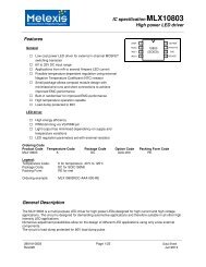
1 Description<br />
<strong>Development</strong> <strong>Kit</strong><br />
MLX91206<br />
REV005 – June 2011<br />
<strong>Development</strong> <strong>Kit</strong><br />
MLX91206<br />
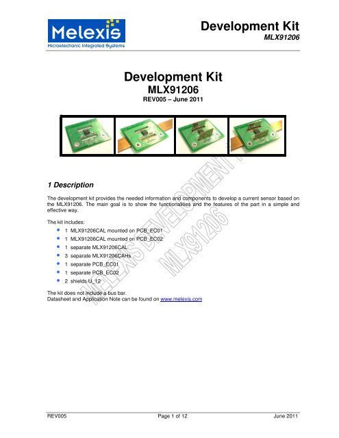
The development kit provides the needed information and components to develop a current sensor based on<br />
the MLX91206. The main goal is to show the functionalities and the features of the part in a simple and<br />
effective way.<br />
The kit includes:<br />
• 1 MLX91206CAL mounted on PCB_EC01<br />
• 1 MLX91206CAL mounted on PCB_EC02<br />
• 1 separate MLX91206CAL<br />
• 3 separate MLX91206CAHs<br />
• 1 separate PCB_EC01<br />
• 1 separate PCB_EC02<br />
• 2 shields U_12<br />
The kit does not include a bus bar.<br />
Datasheet and Application Note can be found on www.melexis.com<br />
REV005 Page 1 of 12 June 2011
2 Specification of EC-01<br />
The included PCB utilizes PCB traces for medium current range measurements.<br />
<strong>Development</strong> <strong>Kit</strong><br />
MLX91206<br />
Layer: Two layer with copper thickness 105µm<br />
The top layer is a conductor<br />
The bottom layer is an expanded ground layer<br />
TOP- layer Bottom- layer<br />
Current: We recommend (1) :<br />
MAX 30A RMS for PCB application<br />
MAX 1kA for Bus bar application<br />
Dimension [l/b/h]: 36.8mm x 30.5mm x 1.6mm<br />
3 Specification of EC-02<br />
The included PCB utilizes PCB loops for small current range measurements.<br />
3.1 Layout<br />
Layer: Four layers,<br />
Top- and Bottom- layer with copper thickness 105µm,<br />
Second- and the Third- layer with copper thickness 35µm<br />
Three loops are on the PCB<br />
Top- layer Second- layer<br />
Third - layer Bottom- layer<br />
Current: We recommend (1) :<br />
MAX 30A RMS for PCB application<br />
MAX 1kA for Bus bar application<br />
Dimension [l/b/h]: 36.8mm x 30.5mm x 2mm<br />
(1): The maximum current is limited by the PCB. For higher currents (> 30A), one can use an external conductor (i.e. a bus bar).<br />
REV005 Page 2 of 12 June 2011
3.2 Details about the “multi-turn” concept<br />
<strong>Development</strong> <strong>Kit</strong><br />
MLX91206<br />
The purpose of the EC-02 PCB is to offer a “coil-like” design, which acts as 3 windings, in order to increase<br />
the sensitivity of the sensor. The PCB consists in 3 layers: top, second and third. This design allows the<br />
current flowing 3 times below the sensor, increasing the field (and the sensitivity) as with a coil.<br />
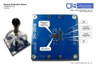
4 Schematic<br />
DUT: MLX91206<br />
C1 100 nF<br />
C2 100 nF<br />
C3 10 nF<br />
C4 10 nF<br />
VDD: pos. supply voltage<br />
VSS: supply common<br />
OUT/PWM: analog sensor output<br />
TEMPOUT: temperature output<br />
CON1 on the PCB:<br />
Pin # Connected to<br />
1 GND/VSS<br />
2 VDD<br />
3 OUT/PWM<br />
4 TEMPOUT<br />
REV005 Page 3 of 12 June 2011
5 Shield description<br />
<strong>Development</strong> <strong>Kit</strong><br />
MLX91206<br />
The shield is made of soft ferromagnetic material (i.e. low cost Fe-Si or Ni-Fe alloys) with a high µr value, this<br />
attracts and concentrates the magnetic flux. In order to get a low hysteresis the shields are annealed after<br />
shaping. Any applied mechanical stress will deteriorate the performance and should be avoided. The purpose<br />
of the shield is to concentrate the wanted signal and to reduce the influence of stray fields. Our shield is<br />
usable for both bus bar and PCB applications.<br />
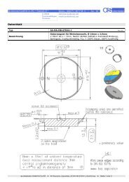
5.1 Settings<br />
View Dimension [mm]<br />
• Material: Mu - Metal with 48%Ni<br />
• Shielding factor is > 50 in the linear range<br />
• Nonlinearity is < 0.05mT in the linear range<br />
• The onset of the saturation starts at about ±25mT<br />
• Weight: 3.14g<br />
5.2 Good to know about shield<br />
Y = thickness =0.8mm<br />
Simulation Recommendation<br />
• The closer the sensor to the ground plate of the shield,<br />
the better the shielding against external stray fields<br />
� try to position the sensor as close as possible to the<br />
ground plate of the shield<br />
• The higher and longer the shield the better the<br />
shielding<br />
� choose the right dimension for your application<br />
• The closer the sensor to the bus bar the better is the<br />
signal to noise ratio<br />
� try to position the sensor as close as possible to the<br />
bus bar<br />
REV005 Page 4 of 12 June 2011
6 OUPUT measurement<br />
6.1 Sensor programming<br />
Sensor: 91206BAH 91206BAL<br />
Sensitivity: 100V/T 250V/T<br />
6.2 OUTPUT range without bus bar (Typical values)<br />
Measured with PCB_EC-01<br />
<strong>Development</strong> <strong>Kit</strong><br />
MLX91206<br />
without shield with shield<br />
91206BAH 91206BAL 91206BAH 91206BAL<br />
Sensitivity [mV/A]: 11.5 28 17 42.5<br />
Current range [A]: +/-200 +/-70 +/-135 +/-50<br />
Measured with PCB_EC-02<br />
without shield with shield<br />
91206BAH 91206BAL 91206BAH 91206BAL<br />
Sensitivity [mV/A]: 25 62 37 92.5<br />
Current range [A]: +/-90 +/-30 +/-50 +/-18<br />
REV005 Page 5 of 12 June 2011
6.3 OUTPUT range with bus bar (Typical values)<br />
Measured with PCB_EC-01 and PCB_EC-02<br />
<strong>Development</strong> <strong>Kit</strong><br />
MLX91206<br />
without shield with shield<br />
91206BAH 91206BAL 91206BAH 91206BAL<br />
Sensitivity [mV/A]: 3.3 8 10 24<br />
Current range [A]: +/-600 +/-240 +/-250 +/-100<br />
• The dimension of the used copper bus bar was 12mm x 100mm x 2mm.<br />
REV005 Page 6 of 12 June 2011
7 Typical output<br />
7.1 Typical output with PCB_EC-01<br />
Output [mV]<br />
4500<br />
4000<br />
3500<br />
3000<br />
2500<br />
2000<br />
1500<br />
1000<br />
500<br />
<strong>Development</strong> <strong>Kit</strong><br />
MLX91206<br />
0<br />
-40 -30 -20 -10 0 10 20 30 40<br />
Current [A]<br />
91206BAL with shield<br />
91206BAL without shield<br />
91206BAH with shield<br />
91206BAH without shield<br />
REV005 Page 7 of 12 June 2011
7.2 Typical output with PCB_EC-02<br />
Output [mV]<br />
5000<br />
4500<br />
4000<br />
3500<br />
3000<br />
2500<br />
2000<br />
1500<br />
1000<br />
500<br />
<strong>Development</strong> <strong>Kit</strong><br />
MLX91206<br />
0<br />
-30 -20 -10 0<br />
Current [A]<br />
10 20 30<br />
91206BAL w ith shield<br />
91206BAL w ithout shield<br />
91206BAH w ith shield<br />
91206BAH w ithout shield<br />
REV005 Page 8 of 12 June 2011
7.3 Typical output with bus bar<br />
Output [mV]<br />
5000<br />
4500<br />
4000<br />
3500<br />
3000<br />
2500<br />
2000<br />
1500<br />
1000<br />
500<br />
0<br />
<strong>Development</strong> <strong>Kit</strong><br />
MLX91206<br />
-200 -150 -100 -50 0 50 100 150 200<br />
Current [A]<br />
MLX92106BAH - with shield<br />
MLX92106BAH - without shield<br />
MLX92106BAL - with shield<br />
MLX92106BAL - without shield<br />
REV005 Page 9 of 12 June 2011
8 Possible programming<br />
8.1 OFFSET vs. XA parameter<br />
OUT [mV]<br />
5000<br />
4500<br />
4000<br />
3500<br />
3000<br />
2500<br />
2000<br />
1500<br />
1000<br />
500<br />
Sum of OUT1 [mV]<br />
<strong>Development</strong> <strong>Kit</strong><br />
MLX91206<br />
0<br />
0 500 1000 1500 2000 2500 3000 3500 4000<br />
XA parameter<br />
• Possible to set the offset voltage between 300 and 4700 mV<br />
8.2 OUT vs. CURRENT with different ROUGHGAIN and FINEGAIN<br />
OUT [mV]<br />
5000<br />
4500<br />
4000<br />
3500<br />
3000<br />
2500<br />
Sum of OUT1 [mV]<br />
2000<br />
0 25 50 75 100 125 150 175 200 225 250 275 300<br />
Current [A]<br />
• Measurements based on bus bar 12mm x 100mm x 2mm<br />
• Demonstrators can be build for ranges from ± 50A to ±250A<br />
Field >25mT<br />
REMARK<br />
ROUGHGAIN<br />
FINEGAIN<br />
CHAR_200A - 1 - 0<br />
CHAR_200A - 1 - 1000<br />
CHAR_200A - 2 - 0<br />
CHAR_200A - 2 - 1000<br />
CHAR_200A - 3 - 0<br />
CHAR_200A - 3 - 1000<br />
CHAR_200A - 4 - 0<br />
CHAR_200A - 4 - 1000<br />
CHAR_200A - 5 - 0<br />
CHAR_200A - 5 - 1000<br />
CHAR_200A - 6 - 0<br />
CHAR_200A - 6 - 1000<br />
REV005 Page 10 of 12 June 2011
8.3 Sensitivity vs. ROUGHGAIN with different FINEGAIN<br />
Sensitivity [mV/A]<br />
50<br />
45<br />
40<br />
35<br />
30<br />
25<br />
20<br />
15<br />
10<br />
5<br />
Sum of Sensitivity [mV/A]<br />
0<br />
0 1 2 3 4 5 6 7<br />
ROUGHGAIN [digits]<br />
• Adjustable sensitivity range from 2mV/A to 40mV/A<br />
<strong>Development</strong> <strong>Kit</strong><br />
MLX91206<br />
REMARK<br />
FINEGAIN<br />
CHAR_200A - 0<br />
CHAR_200A - 1000<br />
REV005 Page 11 of 12 June 2011
Examples of possible demonstrators with MLX91206:<br />
<strong>Development</strong> <strong>Kit</strong><br />
MLX91206<br />
<strong>Melexis</strong> will be happy to support you design-in. Please feel free to contact us for further questions.<br />
Sebastien Grisot<br />
Application Engineer<br />
sgt@melexis.com<br />
REV005 Page 12 of 12 June 2011