MLX90615
MLX90615
MLX90615

You also want an ePaper? Increase the reach of your titles
YUMPU automatically turns print PDFs into web optimized ePapers that Google loves.
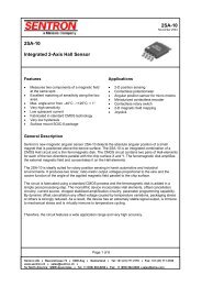
Features and Benefits<br />
Small size, low cost<br />
Easy to integrate<br />
Factory calibrated in wide temperature range:<br />
-40…85˚C for sensor temperature and<br />
-40…115˚C for object temperature<br />
High accuracy of 0.5°C over wide temperature<br />
range (0...+50°C for both TA and TO )<br />
High (medical) accuracy calibration<br />
Measurement resolution of 0.02°C<br />
SMBus compatible digital interface<br />
Power saving mode<br />
Customizable PWM output for continuous<br />
reading<br />
Embedded emissivity compensation<br />
3V supply voltage<br />
Ordering Information<br />
Part No.<br />
<strong>MLX90615</strong><br />
(1) Accuracy<br />
D – medical accuracy<br />
1 Functional diagram<br />
J1<br />
SCL<br />
SDA<br />
Vdd<br />
GND<br />
CON1<br />
Temperature<br />
Code<br />
S (-20°C .. 85°C)<br />
Example:<br />
<strong>MLX90615</strong>SSG-DAA-000-TU<br />
<strong>MLX90615</strong> 4<br />
U1<br />
Vss<br />
SDA<br />
1<br />
Vdd<br />
C1 value and type may differ<br />
in different applications<br />
for optimum EMC<br />
2<br />
SCL<br />
3<br />
C1<br />
0.1uF<br />
Figure 1 Typical application schematics –<br />
<strong>MLX90615</strong> connection to SMBus<br />
<strong>MLX90615</strong><br />
Infra Red Thermometer<br />
Applications Examples<br />
Package<br />
Code<br />
SG (TO-46)<br />
High precision non-contact temperature<br />
measurements<br />
Hand-held thermometers<br />
Ear thermometers<br />
Home appliances with temperature control<br />
Healthcare<br />
Livestock monitoring<br />
Multiple zone temperature control – up to 127<br />
sensors can be read via common 2 wires<br />
- Option Code<br />
- X X X<br />
(1) (2) (3)<br />
(2) Specifics:<br />
A – straight pins for thru hole<br />
mounting<br />
2 General Description<br />
Standard<br />
part<br />
-000<br />
Packing<br />
form<br />
-TU<br />
(3) Package options:<br />
A – 100° FOV<br />
G – 80° FOV<br />
The <strong>MLX90615</strong> is an Infra Red thermometer for non<br />
contact temperature measurements. Both the IR sensitive<br />
thermopile detector chip and the signal conditioning chip are<br />
integrated in the same TO-46 can package.<br />
Thanks to its low noise amplifier, 16-bit ADC and<br />
powerful DSP unit, a high accuracy and resolution of the<br />
thermometer is achieved.<br />
The thermometer comes factory calibrated with the<br />
digital SMBus compatible interface enabled. Readout<br />
resolution is 0.02°C.<br />
3901090615 Page 1 of 32 Data Sheet<br />
Rev 003 30 August 2012
General description (continued)<br />
<strong>MLX90615</strong><br />
Infra Red Thermometer<br />
The <strong>MLX90615</strong> is built from 2 chips, the Infra Red thermopile detector and the signal conditioning<br />
chip MLX90325, specially designed by Melexis to process the output of IR sensor.<br />
The device is available in an industry standard TO-46 package.<br />
Thanks to the low noise amplifier, high resolution 16-bit ADC and powerful DSP unit of the<br />
MLX90325, Melexis is able to deliver a high accuracy and high resolution infrared thermometer. The<br />
calculated object and ambient temperatures are available in the RAM memory of the MLX90325 with a<br />
resolution of 0.02˚C. The values are accessible by 2 wire serial SMBus compatible protocol with a resolution<br />
of 0.02°C or via a 10-bit PWM (Pulse Width Modulated) signal from the device.<br />
The <strong>MLX90615</strong> is factory calibrated in standard temperature ranges from: -40...85˚C for the ambient<br />
temperature and from -40...115˚C for the object temperature.<br />
As a standard, the <strong>MLX90615</strong> is delivered with a programmed object emissivity of 1. It can be easily<br />
customized by the customer for any other emissivity in the range 0.1...1.0 without the need of recalibration<br />
with a black body.<br />
The <strong>MLX90615</strong> can be battery powered.<br />
An optical filter (5.5µm …14µm long-wave pass) that cuts off the visible and near infra-red radiant<br />
flux is integrated in the package to make the sensor insensitive to visible light.<br />
3901090615 Page 2 of 32 Data Sheet<br />
Rev 003 31 July 2012
3 Table of Contents<br />
<strong>MLX90615</strong><br />
Infra Red Thermometer<br />
1 Functional diagram ........................................................................................................................................................................1<br />
2 General Description.......................................................................................................................................................................1<br />
General description (continued).........................................................................................................................................................2<br />
3 Table of Contents ..........................................................................................................................................................................3<br />
4 Glossary of Terms .........................................................................................................................................................................4<br />
5 Maximum ratings ...........................................................................................................................................................................4<br />
6 Pin definitions and descriptions ......................................................................................................................................................5<br />
7 Electrical Specification ...................................................................................................................................................................6<br />
8 Detailed description .......................................................................................................................................................................8<br />
8.1 Block diagram ........................................................................................................................................................................8<br />
8.2 Signal processing principle......................................................................................................................................................8<br />
8.3 Block description ....................................................................................................................................................................8<br />
8.3.1 Amplifier..........................................................................................................................................................................8<br />
8.3.2 Power-On-Reset (POR) ...................................................................................................................................................9<br />
8.3.3 EEPROM ........................................................................................................................................................................9<br />
8.3.4 RAM .............................................................................................................................................................................10<br />
8.4 SMBus compatible 2-wire protocol.........................................................................................................................................11<br />
8.4.1 Functional description ....................................................................................................................................................11<br />
8.4.2 Differences with the standard SMBus specification (reference [1]).....................................................................................11<br />
8.4.3 Detailed description .......................................................................................................................................................11<br />
8.4.4 Bit transfer ....................................................................................................................................................................13<br />
8.4.5 Commands ...................................................................................................................................................................13<br />
8.4.6 SMBus Communication examples ..................................................................................................................................14<br />
8.4.7 Timing specification .......................................................................................................................................................14<br />
8.4.8 Sleep Mode...................................................................................................................................................................15<br />
8.5 Switching between PWM and SMBus ....................................................................................................................................16<br />
8.5.1 PWM to SMBus mode....................................................................................................................................................16<br />
8.5.2 SMBus to PWM mode....................................................................................................................................................16<br />
8.6 PWM ...................................................................................................................................................................................16<br />
8.6.1 PWM format ..................................................................................................................................................................17<br />
8.6.2 Customizing the temperature range for PWM output ........................................................................................................17<br />
8.7 Principle of operation ............................................................................................................................................................19<br />
8.7.1 Ambient temperature TA .................................................................................................................................................19<br />
8.7.2 Object temperature TO ...................................................................................................................................................19<br />
9 Performance Graphs ...................................................................................................................................................................20<br />
9.1 Temperature accuracy of the <strong>MLX90615</strong>................................................................................................................................20<br />
9.2 Field Of View (FOV)..............................................................................................................................................................21<br />
10 Applications Information.............................................................................................................................................................23<br />
10.1 Use of the <strong>MLX90615</strong> thermometer in SMBus configuration ..................................................................................................23<br />
10.2 Use of multiple <strong>MLX90615</strong>s in SMBus configuration..............................................................................................................23<br />
10.3 PWM output .......................................................................................................................................................................24<br />
11 Application Comments ...............................................................................................................................................................25<br />
12 Standard information regarding manufacturability of Melexis products with different soldering processes ........................................26<br />
13 ESD Precautions .......................................................................................................................................................................27<br />
14 FAQ..........................................................................................................................................................................................27<br />
15 Package Information..................................................................................................................................................................29<br />
16 Part marking..............................................................................................................................................................................29<br />
17 Table of figures..........................................................................................................................................................................30<br />
18 References ...............................................................................................................................................................................31<br />
19 Disclaimer .................................................................................................................................................................................31<br />
3901090615 Page 3 of 32 Data Sheet<br />
Rev 003 31 July 2012
4 Glossary of Terms<br />
<strong>MLX90615</strong><br />
Infra Red Thermometer<br />
PTAT Proportional To Absolute Temperature sensor (package temperature)<br />
POR Power On Reset<br />
HFO High Frequency Oscillator (RC)<br />
DSP Digital Signal Processing<br />
FIR Finite Impulse Response. Digital filter<br />
IIR Infinite Impulse Response. Digital filter<br />
IR Infra-Red<br />
DC Direct Current (for settled conditions specifications)<br />
LPF Low Pass Filter<br />
FOV Field Of View<br />
SDA, SCL Serial DAta, Serial CLock – SMBus compatible communication pins<br />
TA<br />
Ambient Temperature measured from the chip – (the package temperature)<br />
TO<br />
Object Temperature, ‘seen’ from IR sensor<br />
ESD Electro-Static Discharge<br />
EMC Electro-Magnetic Compatibility<br />
TBD To Be Defined<br />
Table 1: Glossary of Terms<br />
5 Maximum ratings<br />
Parameter <strong>MLX90615</strong><br />
Supply Voltage, VDD (over voltage) 5V<br />
Supply Voltage, VDD (operating) 3.6V<br />
Reverse Voltage 0.5 V<br />
Operating Temperature Range, TA<br />
-20…+85°C<br />
Storage Temperature Range, TS<br />
-20…+125°C<br />
ESD Sensitivity (AEC Q100 002) 2kV<br />
DC sink current, SDA pin 25 mA<br />
DC clamp current, SDA pin 10 mA<br />
DC clamp current, SCL pin 10 mA<br />
Table 2: Absolute maximum ratings for <strong>MLX90615</strong><br />
Exceeding the absolute maximum ratings may cause permanent damage. Exposure to absolute<br />
maximum rated conditions for extended periods may affect device reliability.<br />
3901090615 Page 4 of 32 Data Sheet<br />
Rev 003 31 July 2012
6 Pin definitions and descriptions<br />
4 VSS 1 SDA / PWM<br />
3 SCL<br />
Bottom view<br />
2 VDD<br />
Figure 2: Pin description <strong>MLX90615</strong><br />
<strong>MLX90615</strong><br />
Infra Red Thermometer<br />
Pin Name Function<br />
SDA / PWM<br />
Digital input / output open drain NMOS. In SMBus mode (factory default) Serial Data<br />
I/O. In PWM mode – PWM output. Weak pull-up (300k typ) is present on this pin.<br />
VDD External supply voltage.<br />
SCL<br />
Serial clock input for 2 wire communications protocol. Weak pull-up (300k typ) is<br />
present on this pin.<br />
VSS Ground. The metal can is also connected to this pin.<br />
Table 3: Pin description <strong>MLX90615</strong><br />
Notes:<br />
For EMC and isothermal conditions reasons, it is highly recommended not to use any electrical connection to<br />
the metal can except by the Vss pin.<br />
Both SCL and SDA pin have input Schmidt trigger when the thermometer is operated in the 2-wire<br />
SMBus interface mode.<br />
3901090615 Page 5 of 32 Data Sheet<br />
Rev 003 31 July 2012
7 Electrical Specification<br />
All parameters are valid for TA = 25 ˚C, VDD =3V (unless otherwise specified)<br />
<strong>MLX90615</strong><br />
Infra Red Thermometer<br />
Parameter Symbol Test Conditions Min Typ Max Units<br />
Supplies<br />
External supply VDD 2.6 3 3.6 V<br />
Supply current IDD No load 0.8 1.5 mA<br />
Supply current<br />
(programming)<br />
IDDpr<br />
No load, erase / write EEPROM<br />
operations<br />
1.5 mA<br />
Power-down supply current Isleep No load, SCL and SDA high 1.1 3 µA<br />
Power On Reset<br />
POR level VPOR<br />
Power-up, power-down<br />
and brown-out<br />
0.8 1.5 1.9 V<br />
VDD rise time TPOR Ensure POR signal 20 ms<br />
Output valid Tvalid After POR 0.5 s<br />
EEPROM<br />
Data retention TA = +85°C 10 years<br />
Erase/write cycles TA = +25°C 100,000 Times<br />
Erase/write cycles TA = +85°C 40,000 Times<br />
Erase cell time Terase 5 ms<br />
Write cell time Twrite 5 ms<br />
Pulse width modulation<br />
PWM resolution PWMres Data band 10 bit<br />
PWM output period PWMT,H,def<br />
PWM output period PWMT,L<br />
PWM period stability dPWMT<br />
Factory default high frequency<br />
PWM, HFO factory calibrated<br />
Low frequency PWM,<br />
HFO factory calibrated<br />
Internal oscillator factory<br />
calibrated, over the entire<br />
operation range and supply<br />
voltage<br />
1.024 ms<br />
102.4 ms<br />
-15 +15 %<br />
Output low Level PWMLO Isink = 2 mA VSS+0.2 V<br />
Output sink current IsinkPWM Vout,L = 0.5V 10 mA<br />
Table 4 Electrical specification parameters of the <strong>MLX90615</strong><br />
3901090615 Page 6 of 32 Data Sheet<br />
Rev 003 31 July 2012
<strong>MLX90615</strong><br />
Infra Red Thermometer<br />
Parameter Symbol Test Conditions Min Typ Max Units<br />
SMBus compatible 2-wire interface *<br />
Input high voltage VIH(TA,V) Over temperature and supply VDD-0.1 V<br />
Input low voltage VIL(TA,V) Over temperature and supply 0.6 V<br />
Output low voltage VOL<br />
Over temperature and supply,<br />
Isink = 2mA<br />
0.2 V<br />
SCL,SDA leakage Ileak VSCL=VDD, VSDA=VDD, TA =+85°C 0.25 A<br />
SCL capacitance CSCL 10 pF<br />
SDA capacitance CSDA 10 pF<br />
Slave address SA Factory default 5B hex<br />
WakeUp Request twake SCL low 8 ms<br />
SMBus Request tREQ SCL low 39 ms<br />
Timeout, low Timeout,L SCL low 21 39 ms<br />
Timeout, high Timeout,H SCL high 52 78 s<br />
Acknowledge setup time Tsuac(MD) 8-th SCL falling edge, Master 1.5 s<br />
Acknowledge hold time Thdac(MD) 9-th SCL falling edge, Master 1.5 s<br />
Acknowledge setup time Tsuac(SD) 8-th SCL falling edge, Slave 2.5 s<br />
Acknowledge hold time Thdac(SD) 9-th SCL falling edge, Slave 1.5 s<br />
Table 5 Electrical specification parameters of the <strong>MLX90615</strong> (continued)<br />
Notes: All the communication and refresh rate timings are given for the nominal calibrated HFO frequency and<br />
will vary with this frequency’s variations.<br />
*SMBus compatible interface is described in details in the SMBus detailed description section. Maximum<br />
number of <strong>MLX90615</strong> devices on one bus is 127, higher pull-up currents are recommended for higher number of devices,<br />
faster bus data transfer rates, and increased reactive loading of the bus.<br />
<strong>MLX90615</strong> is always a slave device on the bus. <strong>MLX90615</strong> can work in both low-power and high-power SMBus<br />
communication.<br />
All voltages are with respect to the Vss (ground) unless otherwise noted.<br />
3901090615 Page 7 of 32 Data Sheet<br />
Rev 003 31 July 2012
8 Detailed description<br />
8.1 Block diagram<br />
IR sensor<br />
<strong>MLX90615</strong><br />
8.2 Signal processing principle<br />
Figure 3: Block Diagram<br />
<strong>MLX90615</strong><br />
Infra Red Thermometer<br />
A DSP embedded in the <strong>MLX90615</strong> controls the measurements, calculates object and ambient<br />
temperatures and does the post-processing of the temperatures to output them through SMBus compatible<br />
interface or PWM (whichever activated).<br />
The output of the IR sensor is amplified by a low noise, low offset chopper amplifier with<br />
programmable gain, then converted by a Sigma Delta modulator to a single bit stream and fed to the DSP for<br />
further processing. The signal passes a FIR low pass filter with fixed length of 65536. The output of the FIR<br />
filter is the measurement result and is available in the internal RAM. Based on results of the above<br />
measurements, the corresponding ambient temperature TA and object temperatures TO are calculated. Both<br />
calculated temperatures have a resolution of 0.02 ˚C.<br />
An additional IIR LPF is programmable in EEPROM and allows customization of the thermometer<br />
output in order to trade-off noise versus settling time (refresh rate of the data in the RAM remain constant).<br />
The IIR filter can also limit effect of spurious objects that may appear in the FOV in some<br />
applications.<br />
The PWM output can be enabled in EEPROM as the POR default. Linearized temperatures (TO or<br />
TA, selectable in EEPROM) are available through the free-running PWM output.<br />
8.3 Block description<br />
8.3.1 Amplifier<br />
t°<br />
OPA ADC<br />
DSP<br />
FIR/IIR<br />
filters<br />
Voltage<br />
Reference<br />
SMBus /<br />
PWM<br />
A low noise, low offset amplifier with programmable gain is used for amplifying the IR sensor voltage.<br />
By carefully designing the input modulator and balanced input impedance, the max offset of the system is<br />
3901090615 Page 8 of 32 Data Sheet<br />
Rev 003 31 July 2012
<strong>MLX90615</strong><br />
Infra Red Thermometer<br />
0.5 V. As the device is factory calibrated any change of gain settings would require new calibration of object<br />
channel.<br />
8.3.2 Power-On-Reset (POR)<br />
The Power On Reset (POR) is connected to the Vdd supply. The on-chip POR circuit provides an<br />
active level of the POR signal when the Vdd voltage rises above approximately 0.5V and holds the entire<br />
<strong>MLX90615</strong> in reset until the Vdd is higher than the specified POR threshold VPOR. During the time POR is<br />
active, the POR signal is available as a weak open drain (active high) at the SDA pin. After the <strong>MLX90615</strong><br />
exits the POR state, the functions programmed in the EEPROM take control of that pin.<br />
8.3.3 EEPROM<br />
A limited number of addresses in the EEPROM memory are of interest for the customer. The whole<br />
EEPROM can be read and written with the SMBus interface. The entire EEPROM content between<br />
addresses 0x04 and 0x0D must be kept unaltered or the factory calibration of the device will be lost.<br />
EEPROM (16X16)<br />
Name Address Write access<br />
PWM T min / SMBus slave address (SA) 0x00 Yes<br />
PWM T range 0x01 Yes<br />
Config 0x02 Yes<br />
Emissivity 0x03 Yes<br />
Melexis reserved (factory calibration) 0x04 Yes<br />
… … …<br />
Melexis reserved (factory calibration) 0x0D Yes<br />
ID number 0x0E No<br />
ID number 0x0F No<br />
Table 6 EERPOM table<br />
SMBus slave address: 7 LSBs (6...0) contains the SMBus slave address that the <strong>MLX90615</strong> will<br />
respond to. Note that all <strong>MLX90615</strong> will respond to SA=0x00 and therefore this value is useless in a network.<br />
Factory default SA is 0x5B, max 127 devices on one line SA=0x01 …0x7F<br />
PWM T min: 15 bit for the minimum temperature when PWM is used – right justified (factory default<br />
is 0x355B, which corresponds to +0.03°C)<br />
PWM T range: 15 bit range for the PWM signal temperature (TMAX – TMIN) – right justified (factory<br />
default is 0x09C4, which corresponds to a PWM range of 50.01°C).<br />
The Config register consist of control bits to configure the thermometer after POR:<br />
3901090615 Page 9 of 32 Data Sheet<br />
Rev 003 31 July 2012
<strong>MLX90615</strong><br />
Infra Red Thermometer<br />
15 14 13 12 11 10 9 8 7 6 5 4 3 2 1 0 Config register bit meaning (0x02)<br />
0 - Comminucation type is PWM<br />
1 - Comminucation type is SMBus<br />
0 - PWM frequency = 1KHz<br />
1 - PWM frequency = 10KHz<br />
0 - PWM output = To<br />
1 - PWM output = Ta<br />
0 0 - GAIN = 1 - Amplifier bypassed<br />
- 0…63 - Internal RC oscillator trimnming<br />
- MLXreserved - DO NOT alter<br />
MLX reserved - DO NOT alter<br />
0 1 - GAIN = 10 MLX reserved - DO NOT alter<br />
1 0 - GAIN = 40 MLX reserved - DO NOT alter<br />
1 1 - GAIN = 40 MLX reserved - DO NOT alter<br />
0 - Internal shunt regulatior disabled<br />
1 - Internal shunt regulatior enabled<br />
0 0 0 - FORBIDDEN COMBINATION<br />
0 0 1 - IIR (2) a1=1, b1=0<br />
0 1 0 - IIR (3) a1=0.5, b1=0.5<br />
0 1 1 - IIR (4) a1=0.333(3), b1=0.666(6)<br />
1 0 0 - IIR (5) a1=0.25, b1=0.75<br />
1 0 1 - IIR (6) a1=0.2, b1=0.8<br />
1 1 0 - IIR (7) a1=0.166(6), b1=0.833(3)<br />
1 1 1 - IIR (8) a1=0.14286, b1=0.87514<br />
0 MLX reserved - DO NOT alter<br />
*Note: IIR setting 000b must be avoided<br />
Table 7 Config register meaning of the <strong>MLX90615</strong> (continued)<br />
Emissivity: Contains the value for object emissivity correction. The <strong>MLX90615</strong> will compensate for the<br />
emissivity of the object measured with respect to that value. The equation for that register is<br />
Emissivity dec2hex<br />
round 16384<br />
Where dec2 hex round x represents decimal to hexadecimal conversion with round-off to nearest<br />
value (not truncation). In this case the physical emissivity values are 0…1. For details about the emissivity<br />
factor in IR measurements refer to the FAQ section of the current document.<br />
Factory default is 0x4000, which sets the thermometer to an emissivity of 1.0 (emissivity correction is off).<br />
8.3.4 RAM<br />
RAM can be read through SMBus interface. Limited numbers of RAM registers, summarized below<br />
are of interest to the customer.<br />
RAM (16x16)<br />
Name Address Read access<br />
Melexis reserved 0x00 Yes<br />
… … …<br />
Melexis reserved 0x04 Yes<br />
Raw IR data 0x05 Yes<br />
TA 0x06 Yes<br />
TO 0x07 Yes<br />
Melexis reserved 0x08 Yes<br />
… … …<br />
Melexis reserved 0x0F Yes<br />
Table 8 RAM address list of the <strong>MLX90615</strong><br />
TA is the <strong>MLX90615</strong> package (ambient) temperature and TO is the object temperature. The output<br />
scale is 0.02°K/LSB. To convert a read object temperature into degrees Celsius the equation is:<br />
T O<br />
C<br />
RAM<br />
0x07<br />
0.<br />
02<br />
273.<br />
15<br />
Raw IR data is in sign (1 bit, the MSB) and magnitude (15 bits) format.<br />
3901090615 Page 10 of 32 Data Sheet<br />
Rev 003 31 July 2012
8.4 SMBus compatible 2-wire protocol<br />
The chip supports a 2 wires serial protocol, build with pins SDA and SCL.<br />
<strong>MLX90615</strong><br />
Infra Red Thermometer<br />
SCL – digital input, used as the clock for SMBus compatible communication. A low pulse on that pin<br />
with duration tREQ switches to the SMBus mode in case the PWM is selected in EEPROM. In case<br />
PWM operation is desired, the SCL pin should be kept high. SMBus is the factory default (via<br />
EEPROM settings).<br />
SDA / PWM – Digital input / NMOS open drain output, used for PWM and input / output for the<br />
SMBus. (SMBus is factory default function).<br />
8.4.1 Functional description<br />
The SMBus interface is a 2-wire protocol, allowing communication between the Master Device (MD)<br />
and one or more Slave Devices (SD). In the system only one master can be present at any given time [1].<br />
The <strong>MLX90615</strong> can only be used as a slave device.<br />
Generally, the MD initiates the start of data transfer by selecting a SD through the Slave Address<br />
(SA).<br />
The MD has read access to the RAM and EEPROM and write access to 14 EEPROM cells (at<br />
addresses 0x00…0x0D). If the access to the <strong>MLX90615</strong> is a read operation, it will respond with 16 data bits<br />
and 8 bit PEC only if its own SA, programmed in the internal EEPROM, is equal to the SA, sent by the<br />
master. The SA feature allows connecting up to 127 devices with 2 wires, unless the system has some of the<br />
specific features described in paragraph 5.2 of reference [1]. In order to provide access to any device or to<br />
assign an address to a SD before it is connected to the bus system, the communication must start with zero<br />
SA followed by low R/W¯ bit. When this command is sent from the MD, the <strong>MLX90615</strong> will always respond<br />
and will ignore the internal chip code information.<br />
Note that EEPROM addresses 0x04…0x0D contain the factory calibration parameters and<br />
should not be altered.<br />
Special care must be taken not to put two <strong>MLX90615</strong> devices with the same SD addresses on<br />
the same bus as <strong>MLX90615</strong> does not support ARP[1].<br />
The MD can force the <strong>MLX90615</strong> into low consumption mode “sleep mode”.<br />
8.4.2 Differences with the standard SMBus specification (reference [1])<br />
There are eleven command protocols for the standard SMBus interface. The <strong>MLX90615</strong> supports only two of<br />
them. Not supported commands are:<br />
Quick Command<br />
Byte commands - Sent Byte, Receive Byte, Write Byte and Read Byte<br />
Process Call<br />
Block commands – Block Write and Write-Block Read Process Call<br />
Supported commands are:<br />
Read Word<br />
Write Word<br />
8.4.3 Detailed description<br />
The SDA pin of the <strong>MLX90615</strong> can operate also as a PWM output, depending on the EEPROM<br />
settings. If PWM is enabled, after POR the SDA pin is directly configured as a PWM output. The PWM mode<br />
can be avoided and the pin can be restored to its Serial Data function by issuing SMBus request condition. If<br />
SMBus mode is set, after POR, the request does not have to be sent.<br />
3901090615 Page 11 of 32 Data Sheet<br />
Rev 003 31 July 2012
8.4.3.1 Bus Protocol<br />
Figure 4: SMBus packet element key<br />
<strong>MLX90615</strong><br />
Infra Red Thermometer<br />
After every 8 bits received by the SD an ACK/NACK is followed. When a MD initiates communication,<br />
it first sends the SA. Only the SD with recognized SA gives ACK, the rest will remain silent. If the SD does not<br />
ACK the MD should stop the communication and repeat the message. A NACK could be received after the<br />
PEC. This means that there is an error in the received message and the MD should try sending the message<br />
again. The PEC calculation includes all bits except the START, REPEATED START, STOP, ACK, and NACK<br />
bits. The PEC is a CRC-8 with polynomial X8+X2+X1+1. The Most Significant Bit of every byte is transmitted<br />
first.<br />
8.4.3.1.1 Read Word (depending on the command – RAM or EEPROM)<br />
1 7 1 1 8 1 1 7 1<br />
S Slave Address Wr A<br />
………..<br />
1 7 1 1 8 1 1<br />
S Slave Address Wr A Data Byte A P<br />
S Start Condition<br />
Sr Repeated Start Condition<br />
Rd Read (bit value of 1)<br />
Wr Write (bit value of 0)<br />
A Acknowledge (this bit can be 0 for ACK and 1 for NACK)<br />
P Stop Condition<br />
PEC Packet Error Code<br />
Master-to-Slave<br />
Slave-to-Master<br />
Command A Sr Slave Address Rd<br />
8 1 8 1 8 1 1<br />
Data Byte Low A Data Byte High A PEC A P<br />
Figure 5: SMBus read word format<br />
………..<br />
3901090615 Page 12 of 32 Data Sheet<br />
Rev 003 31 July 2012<br />
1<br />
A
8.4.3.1.2 Write Word (EEPROM only)<br />
8.4.4 Bit transfer<br />
SDA<br />
SCL<br />
Figure 6: SMBus write word format<br />
Changing data<br />
Sampling data<br />
Figure 7: Bit transfer on SMBus<br />
<strong>MLX90615</strong><br />
Infra Red Thermometer<br />
The data on SDA must be changed when SCL is low (min 300ns after the falling edge of SCL). The<br />
data is fetched by both MD and SDs on the rising edge of the SCL. The recommended timing for changing<br />
data is in the middle of the period when the SCL is low<br />
8.4.5 Commands<br />
1 7 1 1 8 1<br />
S Slave Address Wr A<br />
Command A<br />
8 1 8 1 8 1<br />
1<br />
……….. Data Byte Low A Data Byte High A PEC A P<br />
In application mode RAM and EEPROM can be read both with 16x16 sizes. (For example, TO - RAM<br />
address 0x07 will sweep between 0x2D8A to 0x4BD0 as the object temperature rises from -40°C to +115°C).<br />
The MSB read from RAM is an error flag (active high) for the linearized temperatures (TO and TA).<br />
Opcode Command<br />
0001 aaaa* EEPROM Access<br />
0010 aaaa* RAM Access<br />
1100 0110 Enter SLEEP mode<br />
Table 9 Command list for the <strong>MLX90615</strong><br />
………..<br />
NOTE*: The aaaa are the 4 LSBits of the memory map address to be read / written<br />
3901090615 Page 13 of 32 Data Sheet<br />
Rev 003 31 July 2012
8.4.6 SMBus Communication examples<br />
SDA<br />
SCL<br />
SA_W=0xB6 Command=0x27<br />
SA_R=0xB7<br />
LSByte=0x5B<br />
<strong>MLX90615</strong><br />
Infra Red Thermometer<br />
MSByte=0x3C<br />
PEC=0xF5<br />
S 1 0 1 1 0 1 1 W A 0 0 1 0 0 1 1 1 A 1 S 1 0 1 1 0 1 1 R A 0 1 0 1 1 0 1 1 A 0 0 1 1 1 1 0 0 A 1 1 1 1 0 1 0 1 A P<br />
SDA<br />
SCL<br />
Figure 8: SMBus read word format (SA=0x5B, read RAM=0x07, result = 0x3C5B)<br />
SA_W=0xB6 Command=0x13<br />
LSByte=0x99<br />
MSbyte=0x39<br />
PEC=0x00<br />
S 1 0 1 1 0 1 1 W A 0 0 0 1 0 0 1 1 A 1 0 0 1 1 0 0 1 A 0 0 1 1 1 0 0 1 A 0 0 0 0 0 0 0 0 A<br />
Figure 9: SMBus write word format (SA=0x5B, Write=0x3999 to EEPROM 0x03)<br />
Note: Before a write operation to takes place, the EEPROM cell needs to be erased. An erase<br />
operation is simply a writing of 0x0000 at the same EEPROM address. Care needs to be taken not to alter<br />
factory calibration (EEPROM addresses 0x04…0x0D).<br />
8.4.7 Timing specification<br />
The <strong>MLX90615</strong> meets all the timing specifications of the SMBus [1] except the values given in the<br />
Electrical specifications section.The maximum frequency of the <strong>MLX90615</strong> SMBus clock is 100 kHz and the<br />
minimum is 10 kHz.<br />
The specific timings for the <strong>MLX90615</strong>’s SMBus are:<br />
SMBus Request ( ) is the time that the SCL should be forced low in order to switch <strong>MLX90615</strong><br />
from thermal relay mode to SMBus mode – at least 39 ms<br />
Timeout L is the maximum allowed time for SCL to be low. After this time the <strong>MLX90615</strong> will reset its<br />
communication block and will be ready for new communication - not more than 21ms<br />
Timeout H is the maximum time for which it is allowed for SCL to be high during communication. After<br />
this time <strong>MLX90615</strong> will reset its communication block assuming that the bus is idle (according to the SMBus<br />
specification) - not more than 52µs<br />
Tsuac(SD) is the time after the eighth falling edge of SCL during which the <strong>MLX90615</strong> will force SDA<br />
low to acknowledge the last received byte – not more than 2.5µs<br />
Thdac(SD) is the time after the ninth falling edge of SCL during which the <strong>MLX90615</strong> will release the<br />
SDA (so the MD can continue with the communication) – not more than 1.5µs<br />
Tsuac(MD) is the time after the eighth falling edge of SCL during which the <strong>MLX90615</strong> will release<br />
SDA (so that the MD can acknowledge the last received byte) – not more than 1.5µs<br />
Thdac(MD) is the time after the ninth falling edge of SCL during which the <strong>MLX90615</strong> will take control<br />
of the SDA (so it can continue with the next byte to transmit) – not more than 1.5µs<br />
The indexes MD and SD for the latest timings are used – MD when the master device is making the<br />
acknowledge; SD when the slave device is making the acknowledge). For other timings see [1].<br />
3901090615 Page 14 of 32 Data Sheet<br />
Rev 003 31 July 2012<br />
P
SDA<br />
SCL<br />
8.4.8 Sleep Mode<br />
Timeout_L<br />
<strong>MLX90615</strong><br />
Infra Red Thermometer<br />
1 0 1 0 1 0 1 1 ACK<br />
1 2 3 4 5 6 7 8 9<br />
3901090615 Page 15 of 32 Data Sheet<br />
Rev 003 31 July 2012<br />
> 21ms<br />
Figure 10: SMBus timing<br />
> 52µs<br />
Timeout_H<br />
Tsuac Thdac<br />
MD < 1.5µs<br />
SD < 2.5µs<br />
MD < 1.5µs<br />
SD < 1.5µs<br />
Sleep mode is available in SMBus mode only.<br />
<strong>MLX90615</strong> can enter Sleep Mode via command “Enter SLEEP mode” sent via the SMBus interface.<br />
SCL needs to be high during Sleep. SDA can idle in each state at the same time, but the high state is<br />
recommended as the pull-up does not add current drain. There are weak pull-ups on both SCL and SDA pins.<br />
8.4.8.1 Enter Sleep Mode<br />
SDA<br />
SCL<br />
SA_W=0xB6 Command=0xC6<br />
PEC=0x6D<br />
S 1 0 1 1 0 1 1 W A 1 1 0 0 0 1 1 0 A 0 1 1 0 1 1 0 1 A<br />
8.4.8.2 Exit Sleep Mode<br />
Normal operation mode Sleep mode<br />
Figure 11: Enter sleep mode command (SA=0x5B, Command=0xC6,PEC=0x6D)<br />
<strong>MLX90615</strong> goes back into power-up default mode by forcing the SCL pin low for at least twake > 8ms.<br />
Exit from Sleep is always in SMBus mode. Valid data will be available typically 0.3 seconds after the device<br />
has woken up.<br />
SCL<br />
Sleep mode Normal mode<br />
> 8ms<br />
Figure 9: Exit Sleep Mode<br />
P
8.5 Switching between PWM and SMBus<br />
8.5.1 PWM to SMBus mode<br />
<strong>MLX90615</strong><br />
Infra Red Thermometer<br />
The diagram below illustrates how to switch to SMBus if PWM is enabled. If PWM is enabled, the<br />
<strong>MLX90615</strong>’s SMBus Request condition is needed to disable PWM and reconfigure SDA/PWM pin before<br />
starting SMBus communication. The <strong>MLX90615</strong>’s SMBus request condition requires forcing the SCL pin<br />
LOW for a period longer than the request time (tREQ>39ms). The SDA / PWM line value is ignored in this<br />
case. Note that after power ON / OFF the sensor will be in PWM mode if bit 0 from Config register is not set<br />
in SMBus mode.<br />
PWM mode SMBus mode<br />
SDA<br />
SCL<br />
8.5.2 SMBus to PWM mode<br />
>39ms<br />
Figure 12: Switching from PWM to SMBus mode<br />
If SMBus mode is set by default, PWM mode can be set only by setting bit 0 from Config register to<br />
PWM mode and switching the supply OFF then ON.<br />
8.6 PWM<br />
The <strong>MLX90615</strong> can be read via PWM or SMBus compatible interface. Selection of PWM output is<br />
done in EEPROM configuration (factory default is SMBus). Object or ambient temperature can be read<br />
through PWM. The PWM period is derived from the on-chip oscillator and is programmable in a low (10 Hz)<br />
or high (1 KHz) frequency mode.<br />
Temperature ranges for the PWM output are determined by the contents of the cells 0x00, 0x01 in<br />
the EEPROM – PWM ToMIN and PWMRANGE (ToMAX - ToMIN), scale is 0.02°K/LSB.<br />
Note that in SMBus mode the EEPROM address 0x00 (LSByte) is used for Slave address SA.<br />
Note that the SCL pin needs to be kept high in order to use the PWM function or to be left unconnected as<br />
there is a weak pull up build in.<br />
Start<br />
Valid data band<br />
t1 t2 t3<br />
0 1<br />
T<br />
5<br />
T<br />
8<br />
8<br />
3901090615 Page 16 of 32 Data Sheet<br />
Rev 003 31 July 2012<br />
S<br />
Figure 13 PWM format<br />
P<br />
T
8.6.1 PWM format<br />
The temperature reading can be calculated from the signal timing as:<br />
Tout<br />
2<br />
t2<br />
T<br />
T<br />
MAX<br />
T<br />
MIN<br />
T<br />
MIN<br />
<strong>MLX90615</strong><br />
Infra Red Thermometer<br />
where Tmin and Trange are the corresponding rescale coefficients in EEPROM for the selected temperature<br />
output and T is the PWM period. Tout is TO or TA according to bit Config Register, 2.<br />
The different time intervals t1, t2 and t3 have the following functions:<br />
t 1:<br />
Start buffer. During this time the signal is always high. t1 to fig. 14).<br />
0.<br />
125 T (T is the PWM period, refer<br />
t 2 : Valid Data Output Band, 0 to 1/2T. PWM output data resolution is 10 bit.<br />
t : always low signal.<br />
3<br />
The maximum duty cycle is limited to t 1 t2<br />
0.<br />
625 this means that the PWM line will never go<br />
static, allowing detection of fault on the line (disconnected device, short on the line).<br />
8.6.2 Customizing the temperature range for PWM output<br />
The calculated ambient and object temperatures are stored in RAM with a resolution of 0.02°C (15<br />
bit). The PWM operates with a 10-bit number so the transmitted temperature is rescaled in order to fit in the<br />
desired range.<br />
For this goal 2 cells in EEPROM are foreseen to store the desired temperature range, PWM TMIN and<br />
PWM TRANGE.<br />
Thus the output range can be programmed with an accuracy of 0.02 °C.<br />
The data for PWM is rescaled according to the following equation:<br />
T<br />
PWM<br />
T<br />
RAM<br />
K<br />
T<br />
MIN<br />
EEPROM<br />
PWM<br />
, K<br />
PWM<br />
T<br />
RANGEEEPROM<br />
1023<br />
The TRAM is the linearized temperature, 15-bit (0x2D8A…0x4BD0, -40 ..+115°C) and the result is a<br />
10-bit word, in which 0x000 corresponds to PWM TMIN[°C], 0x3FF corresponds to PWM TMAX[°C] and 1LSB<br />
corresponds to:<br />
1 LSB<br />
TMAX<br />
TMIN<br />
,<br />
1023<br />
C<br />
T<br />
Example:<br />
MAX<br />
T<br />
MIN<br />
T<br />
TMIN T<br />
EEPORM MIN<br />
RANGE<br />
50 LSB<br />
TMAX TMAX<br />
50 LSB<br />
EEPORM<br />
3901090615 Page 17 of 32 Data Sheet<br />
Rev 003 31 July 2012
Figure 14: PWM example<br />
<strong>MLX90615</strong><br />
Infra Red Thermometer<br />
To 0 C EEPROM, 0x00 50 To 273.<br />
15 13658d<br />
0x355A<br />
MIN<br />
PWM<br />
RANGE<br />
To<br />
ToMIN MIN<br />
MAX<br />
To<br />
MIN<br />
50 C<br />
PWM RANGE<br />
RANGE MAX MIN<br />
EEPROM , 0x01<br />
50 PWM To To 50 50 2500d<br />
0x09C<br />
4<br />
Captured PWM period is T = 1004 s (or frequency is 996 Hz i.e. high frequency mode is selected)<br />
Captured high duration is t = 392 s<br />
Calculated duty cycle is:<br />
t 392<br />
D 0.<br />
3904 or 39 . 04%<br />
T 1004<br />
The temperature is calculated as follows:<br />
T O<br />
2<br />
0.<br />
3904<br />
0.<br />
125<br />
50<br />
0<br />
0<br />
2<br />
0.<br />
2654<br />
26.<br />
54<br />
Where 0.125 is START period (always high) which carry no temperature information and must be subtracted.<br />
3901090615 Page 18 of 32 Data Sheet<br />
Rev 003 31 July 2012<br />
50<br />
C
8.7 Principle of operation<br />
<strong>MLX90615</strong><br />
Infra Red Thermometer<br />
The IR sensor consists of series connected thermo-couples with cold junctions placed at thick chip substrate<br />
and hot junctions, placed over thin membrane. The IR radiation absorbed from the membrane heats (or<br />
cools) it. The thermopile output signal is<br />
V T , T<br />
ir<br />
A<br />
O<br />
A<br />
T<br />
O<br />
T<br />
A<br />
Where TO is the object absolute temperature (Kelvin), TA is the sensor die absolute (Kelvin) temperature, and<br />
A is the overall sensitivity.<br />
An additional sensor is needed for the chip temperature. After measurement of the output of both sensors,<br />
the corresponding ambient and object temperatures can be calculated. These calculations are done by the<br />
internal DSP, which produces digital outputs, linearly proportional to measured temperatures.<br />
8.7.1 Ambient temperature TA<br />
The Sensor die temperature is measured with a PTAT element. All the sensors conditioning and data<br />
processing is handled on-chip and the linearized sensor die temperature TA is available in RAM (address<br />
0x06).<br />
The resolution of the calculated TA is 0.02˚C. The sensor is factory calibrated for the range -20 … +85˚C.<br />
Example:<br />
RAM ( 0x06)<br />
0x3171<br />
corresponding to -20.01˚C<br />
RAM( 0x06)<br />
0x45F<br />
3corresponding<br />
to +84.99˚C<br />
Conversion RAM content to real TA is easy done with following expression:<br />
TA[ K]<br />
0.<br />
02 TA<br />
_ REG<br />
8.7.2 Object temperature TO<br />
The result has a resolution of 0.02˚C and is available in RAM (address 0x07). To is derived from<br />
RAM as:<br />
Example:<br />
TO[ K]<br />
0.<br />
02 TO<br />
_ REG<br />
RAM ( 0x07)<br />
0x2D89<br />
corresponding to -40.01˚C<br />
RAM( 0x07)<br />
0x4BCF<br />
corresponding to +114.99˚C<br />
3901090615 Page 19 of 32 Data Sheet<br />
Rev 003 31 July 2012
<strong>MLX90615</strong><br />
Infra Red Thermometer<br />
Unique Features<br />
The <strong>MLX90615</strong> is a ready to use low-cost non contact thermometer provided by Melexis with output<br />
data linearly dependent on the object temperature with high accuracy and extended resolution.<br />
The user can program the internal object emissivity correction for objects with a low emissivity.<br />
The <strong>MLX90615</strong> is housed in standard TO46 package.<br />
The low power consumption and sleep mode make the thermometer ideally suited for handheld<br />
mobile applications.<br />
The digital sensor interface can be either a PWM or an enhanced access SMBus compatible<br />
protocol. Systems with more than 100 devices can be built with only two signal lines.<br />
9 Performance Graphs<br />
9.1 Temperature accuracy of the <strong>MLX90615</strong><br />
115°C<br />
60°C<br />
0°C<br />
-40°C<br />
±3°C<br />
±2°C<br />
±3°C<br />
±2°C<br />
±1.5°C<br />
±1.5°C<br />
To, °C<br />
±1.5°C<br />
±0.5°C<br />
±1.5°C<br />
±1.5°C<br />
±1.5°C<br />
-20°C 0°C 50°C 85°C<br />
Figure 14: Accuracy of <strong>MLX90615</strong> (TA, TO)<br />
All accuracy specifications apply under settled isothermal conditions only and nominal supply voltage.<br />
3901090615 Page 20 of 32 Data Sheet<br />
Rev 003 31 July 2012<br />
±2°C<br />
Ta, °C<br />
The accuracy for the <strong>MLX90615</strong>SSG-DAX in the range TA =16°C …40°C and TO= 32°C …42°C is shown<br />
in diagram below. The accuracy for the rest ranges is same as in previous diagram.
To, °C<br />
42<br />
39<br />
36<br />
32<br />
10<br />
16<br />
± 0.3°C<br />
± 0.2°C<br />
± 0.3°C<br />
20 30 40<br />
<strong>MLX90615</strong><br />
Infra Red Thermometer<br />
Ta, °C<br />
Figure 15: Accuracy of <strong>MLX90615</strong>SSG-DAx (TA, TO) is according to ASTM standard point 5.3<br />
9.2 Field Of View (FOV)<br />
Field of view is determined at 50% thermopile signal and with respect to the sensor main axis.<br />
Parameter <strong>MLX90615</strong>SSG-XAA <strong>MLX90615</strong>SSG-XAG<br />
Peak direction ±0° ±0°<br />
FOV width 100°±5° 80°±5°<br />
1.0<br />
0.8<br />
0.5<br />
0.3<br />
Table 10 FOV options for the <strong>MLX90615</strong><br />
0.0<br />
-80° -70° -60° -50° -40° -30° -20° -10° 0° 10° 20° 30° 40° 50° 60° 70° 80°<br />
Angle, Deg<br />
Figure 16: Typical FOV of <strong>MLX90615</strong>SSG-DAA<br />
3901090615 Page 21 of 32 Data Sheet<br />
Rev 003 31 July 2012
Normalized signal<br />
1.0<br />
0.8<br />
0.5<br />
0.3<br />
FOV<br />
<strong>MLX90615</strong><br />
Infra Red Thermometer<br />
0.0<br />
-80° -70° -60° -50° -40° -30° -20° -10° 0° 10° 20° 30° 40° 50° 60° 70° 80°<br />
Angle, Deg<br />
Figure 17: Typical FOV of <strong>MLX90615</strong>SSG-DAG<br />
3901090615 Page 22 of 32 Data Sheet<br />
Rev 003 31 July 2012
10 Applications Information<br />
10.1 Use of the <strong>MLX90615</strong> thermometer in SMBus configuration<br />
C1<br />
Vdd<br />
2<br />
0.1uF<br />
1 <strong>MLX90615</strong><br />
SDA U1<br />
/P WM<br />
SCL<br />
3<br />
4<br />
Vss<br />
R1<br />
<strong>MLX90615</strong><br />
Infra Red Thermometer<br />
3901090615 Page 23 of 32 Data Sheet<br />
Rev 003 31 July 2012<br />
R2<br />
SMBus<br />
+3.3V<br />
Vdd<br />
SDA<br />
SCL<br />
GND<br />
U2 MCU<br />
Figure 18: Connection of <strong>MLX90615</strong> to SMBus.<br />
<strong>MLX90615</strong> has diode clamps SDA/SCL to Vdd so it is necessary to provide <strong>MLX90615</strong> with power in<br />
order not to load the SMBus lines.<br />
10.2 Use of multiple <strong>MLX90615</strong>s in SMBus configuration<br />
C1<br />
Vdd<br />
2<br />
0.1uF<br />
C2<br />
Vdd<br />
2<br />
0.1uF<br />
1 <strong>MLX90615</strong><br />
SDA U2<br />
/PW M<br />
SCL<br />
3<br />
SCL<br />
3<br />
Vss<br />
4<br />
1 <strong>MLX90615</strong><br />
SDA U3<br />
/PW M<br />
4<br />
Vss<br />
I1<br />
Ipu1<br />
I2<br />
Ipu2<br />
Current source or resistor<br />
pull-ups of the bus<br />
R1 R2<br />
SDA<br />
SMBus<br />
+3.3V<br />
C3<br />
Cbus1<br />
Cbus2<br />
C4<br />
SCL<br />
Vdd<br />
SDA<br />
SCL<br />
GND<br />
U1 MCU<br />
Figure 19: Use of multiple <strong>MLX90615</strong> devices in SMBus network<br />
The <strong>MLX90615</strong> supports a 7-bit slave address in EEPROM, thus allowing up to 127 devices to be<br />
read via two common wires. Current source pull-ups may be preferred with higher capacitive loading on the<br />
bus (C3 and C4 represent the lines’ parasitic), while simple resistive pull-ups provide the obvious low cost<br />
advantage.
10.3 PWM output<br />
<strong>MLX90615</strong><br />
Infra Red Thermometer<br />
With PWM output configuration <strong>MLX90615</strong> can be read via single wire. Output is open drain NMOS<br />
(with a weak pull-up, 300k typ). Therefore external pull-up is required for high level state on the line with<br />
longer wires. Simple level shifting is possible with a single resistor. ESD protective clamp on the SDA pin<br />
consists of 4 diodes to Vdd, thus allowing high level to go up to 5V disregarding the <strong>MLX90615</strong> supply<br />
voltage value.<br />
C1<br />
SCL<br />
3<br />
2<br />
Vdd<br />
Vss<br />
0.1uF 4<br />
1<br />
SDA<br />
U1<br />
<strong>MLX90615</strong><br />
PW M Capture<br />
3901090615 Page 24 of 32 Data Sheet<br />
Rev 003 31 July 2012<br />
R1<br />
10k<br />
MCU<br />
Vss<br />
Vdd<br />
Figure 20: Using <strong>MLX90615</strong> PWM output<br />
In EEPROM two PWM periods can be programmed – 102.4 or 1 ms (typ). With remote installation (wires)<br />
PWM is recommended as more robust to EMI than the SMBus and the high PWM period would be<br />
also preferred. As a factory default, once PWM is enabled, output will cover 0…50°C object temperature<br />
range (as 12.5 … 62.5% duty cycle) at 1 kHz frequency.<br />
C2<br />
+3V<br />
+Vdd2<br />
+Vdd2 may be +1.8...+5V<br />
according to the MCU<br />
used
11 Application Comments<br />
<strong>MLX90615</strong><br />
Infra Red Thermometer<br />
Significant contamination at the optical input side (sensor filter) might cause unknown additional<br />
filtering/distortion of the optical signal and therefore result in unspecified errors.<br />
IR sensors are inherently susceptible to errors caused by thermal gradients. There are physical<br />
reasons for that phenomenon and, in spite of the careful design of the <strong>MLX90615</strong>, it is recommended not to<br />
subject the <strong>MLX90615</strong> to heat transfer and especially transient conditions.<br />
Upon power-up the <strong>MLX90615</strong> passes embedded checking and calibration routines. During these<br />
routines the output is not defined and it is recommended to wait for the specified POR time before reading the<br />
module. Very slow power-up may cause the embedded POR circuitry trigger on inappropriate levels, resulting<br />
in unspecified operation and is not recommended.<br />
The <strong>MLX90615</strong> is designed and calibrated to operate as a non contact thermometer in settled<br />
conditions. Using the module in very different way will result in unknown results.<br />
Capacitive loading on a SMBus can degrade the communication. Some improvement is possible<br />
with use of current sources compared to resistors in pull-up circuitry. Further improvement is possible with<br />
specialized commercially available bus accelerators. With the <strong>MLX90615</strong> additional improvement is possible<br />
with increasing the pull-up current (decreasing the pull-up resistor values). Input levels for SMBus compatible<br />
mode have higher overall tolerance than the SMBus specification, but the output low level is rather low even<br />
with the high-power SMBus specification for pull-up currents. Another option might be to go for a slower<br />
communication (clock speed), as the <strong>MLX90615</strong> implements Schmidt triggers on it’s inputs in SMBus<br />
compatible mode and is therefore not really sensitive to rise time of the bus (it is more likely the rise time to<br />
be an issue than the fall time, as far as the SMBus systems are open drain with pull-up).<br />
For ESD protection there are clamp diodes between the Vss and Vdd and each of the other pins.<br />
This means that the <strong>MLX90615</strong> might draw current from a bus in case the SCL and/or SDA is connected and<br />
the Vdd is lower than the bus pull-ups’ voltage.<br />
It is possible to use the <strong>MLX90615</strong> in applications, powered directly from the AC line (trasformerless).<br />
In such cases it is very important not to forget that the metal package of the sensor is not isolated and<br />
therefore may occur to be connected to that line, too. Melexis can not be responsible for any application like<br />
this and highly recommends not using the <strong>MLX90615</strong> in that way.<br />
Check www.melexis.com for most current application notes about <strong>MLX90615</strong>.<br />
3901090615 Page 25 of 32 Data Sheet<br />
Rev 003 31 July 2012
<strong>MLX90615</strong><br />
Infra Red Thermometer<br />
12 Standard information regarding manufacturability of Melexis<br />
products with different soldering processes<br />
Our products are classified and qualified regarding soldering technology, solderability and moisture<br />
sensitivity level according to following test methods:<br />
Reflow Soldering SMD’s (Surface Mount Devices)<br />
IPC/JEDEC J-STD-020<br />
Moisture/Reflow Sensitivity Classification for No hermetic Solid State Surface Mount Devices<br />
(classification reflow profiles according to table 5-2)<br />
EIA/JEDEC JESD22-A113<br />
Preconditioning of Nonhermetic Surface Mount Devices Prior to Reliability Testing<br />
(reflow profiles according to table 2)<br />
Wave Soldering SMD’s (Surface Mount Devices) and THD’s (Through Hole Devices)<br />
EN60749-20<br />
Resistance of plastic- encapsulated SMD’s to combined effect of moisture and soldering heat<br />
EIA/JEDEC JESD22-B106 and EN60749-15<br />
Resistance to soldering temperature for through-hole mounted devices<br />
The application of Wave Soldering for SMD’s is allowed only after consulting Melexis regarding assurance of<br />
adhesive strength between device and board!<br />
Iron Soldering THD’s (Through Hole Devices)<br />
EN60749-15<br />
Resistance to soldering temperature for through-hole mounted devices<br />
Solderability SMD’s (Surface Mount Devices) and THD’s (Through Hole Devices)<br />
EIA/JEDEC JESD22-B102 and EN60749-21<br />
Solderability<br />
For all soldering technologies deviating from above mentioned standard conditions (regarding peak<br />
temperature, temperature gradient, temperature profile etc) additional classification and qualification tests<br />
have to be agreed upon with Melexis.<br />
General precautions for soldering, handling or cleaning:<br />
- Thermal Stresses above the absolute maximum ratings during application or storage may cause damages<br />
to the device.<br />
- Do not expose the sensor to aggressive detergents such as Freon, Trichloroethylene, etc.<br />
- Windows may be cleaned with alcohol and cotton swab at ambient temperatures.<br />
- Rework by manual soldering can be done with soldering iron temperature maximum 350°C for maximum 5<br />
sec.<br />
- Avoid heat exposure to the top and the window of the package.<br />
- Do not apply pressure (force) on the window or top of the package, especially when TA temperature is<br />
above 85°C.<br />
- Temperatures above absolute maximum rating and/or mechanical pressure on the window or top of the<br />
package may cause loss of hermeticity and as a result penetration of a humid air inside the package, bond<br />
pad and wire corrosion, leading to degradation or loss of function.<br />
3901090615 Page 26 of 32 Data Sheet<br />
Rev 003 31 July 2012
<strong>MLX90615</strong><br />
Infra Red Thermometer<br />
- When considering reflow soldering, measure the temperature profile of the top of the can and keep the peak<br />
temperature as low as possible.<br />
- Please contact Melexis in case you intend to use a reflow soldering process for through hole devices to<br />
verify your soldering process design.<br />
Melexis is contributing to global environmental conservation by promoting lead free solutions. For<br />
more information on qualifications of RoHS compliant products (RoHS = European directive on the<br />
Restriction Of the use of certain Hazardous Substances) please visit the quality page on our website:<br />
http://www.melexis.com/quality.asp<br />
The <strong>MLX90615</strong> is RoHS compliant<br />
13 ESD Precautions<br />
Electronic semiconductor products are sensitive to Electro Static Discharge (ESD).<br />
Always observe Electro Static Discharge control procedures whenever handling semiconductor<br />
products.<br />
14 FAQ<br />
When I measure aluminium and plastic parts settled at the same conditions I get significant<br />
errors on aluminium. Why?<br />
Different materials have different emissivity. A typical value for aluminium (roughly polished) is 0.18<br />
and for plastics values of 0.84…0.95 are typical. IR thermometers use the radiation flux between the sensitive<br />
element in the sensor and the object of interest, given by the equation<br />
Where<br />
4<br />
q 1 1 T1<br />
A1<br />
Fa<br />
b<br />
1 and 2 are the emissivity of the two objects,<br />
1 is the absorptivity of the sensor (in this case),<br />
is the Stefan-Boltzmann constant,<br />
A1 and A2 are the surface areas involved in the radiation heat transfer,<br />
Fa-b is the shape factor,<br />
T1 and T2 are known temperature of the sensor die (measured with specially integrated and calibrated<br />
element) and the object temperature that we need.<br />
Note that these are all in Kelvin, heat exchange knows only physics.<br />
When a body with low emissivity (such as aluminium) is involved in this heat transfer, the portion of<br />
the radiation incident to the sensor element that really comes from the object of interest decreases – and the<br />
reflected environmental IR emissions take place. (This is all for bodies with zero transparency in the IR band.)<br />
The IR thermometer is calibrated to stay within specified accuracy – but it has no way to separate the<br />
incoming IR radiation into real object and reflected environmental part. Therefore, measuring objects with low<br />
emissivity is a very sophisticated issue and infra-red measurements of such materials is a specialised field.<br />
What can be done to solve that problem? Look at paintings – for example, oil paints are likely to have<br />
emissivity of 0.85…0.95 – but keep in mind that the stability of the paint emissivity has inevitable impact on<br />
measurements.<br />
It is also a good point to keep in mind that not everything that looks black is “black” also for IR. For<br />
example, even heavily oxidized aluminium has still emissivity as low as 0.30.<br />
How high is enough? Not an easy question – but, in all cases the closer you need to get to the real<br />
object temperature the higher the needed emissivity will be, of course.<br />
3901090615 Page 27 of 32 Data Sheet<br />
Rev 003 31 July 2012<br />
2<br />
T<br />
4<br />
2<br />
A<br />
2<br />
,
<strong>MLX90615</strong><br />
Infra Red Thermometer<br />
With the real life emissivity values the environmental IR comes into play via the reflectivity of the<br />
object (the sum of Emissivity, Reflectivity and Absorptivity gives 1.00 for any material). The larger the<br />
difference between environmental and object temperature is at given reflectivity (with an opaque for IR<br />
material reflectivity equals 1.00 minus emissivity) the bigger errors it produces.<br />
After I put the <strong>MLX90615</strong> in the dashboard I start getting errors larger than specified in spite<br />
that the module was working properly before that. Why?<br />
Any object present in the FOV of the module provides IR signal. It is actually possible to introduce<br />
error in the measurements if the module is attached to the dashboard with an opening that enters the FOV. In<br />
that case portion of the dashboard opening will introduce IR signal in conjunction with constraining the<br />
effective FOV and thus compromising specified accuracy. Relevant opening that takes in account the FOV is<br />
a must for accurate measurements. Note that the basic FOV specification takes 50% of IR signal as threshold<br />
(in order to define the area, where the measurements are relevant), while the entire FOV at lower level is<br />
capable of introducing lateral IR signal under many conditions.<br />
When a hot (cold) air stream hits my <strong>MLX90615</strong> some error adds to the measured temperature<br />
I read. What is it?<br />
IR sensors are inherently sensitive to difference in temperatures between the sensitive element and<br />
everything incident to that element. As a matter of fact, this element is not the sensor package, but the sensor<br />
die inside. Therefore, a thermal gradient over the sensor package will inevitably result in additional IR flux<br />
between the sensor package and the sensor die. This is real optical signal that can not be segregated from<br />
the target IR signal and will add errors to the measured temperature.<br />
Thermal gradients with impact of that kind are likely to appear during transient conditions. The sensor<br />
used is developed with care about sensitivity to this kind of lateral phenomena, but their nature demands<br />
some care when choosing place to use the <strong>MLX90615</strong> in order to make them negligible.<br />
I measure human body temperature and I often get measurements that significantly differ<br />
from the +37°C I expect.<br />
IR measurements are true surface temperature measurements. In many applications this means that<br />
the actual temperature measured by an IR thermometer will be temperature of the clothing and not the skin<br />
temperature. Emissivity (explained first in this section) is another issue with clothes that has to be considered.<br />
There is also the simple chance that the measured temperature is adequate – for example, in a cold winter<br />
human hand can appear at temperatures not too close to the well known +37°C.<br />
I consider using <strong>MLX90615</strong> to measure temperature within car compartment, but I am<br />
embarrassed about the Sun light that may hit the module. Is it a significant issue?<br />
Special care is taken to cut off the visible light spectra as well as the NIR (near IR) before it reaches<br />
the sensitive sensor die. Even more, the glass (in most cases) is not transparent to the IR radiation used by<br />
the <strong>MLX90615</strong>. Glass has temperature and really high emissivity in most cases – it is “black” for IR of<br />
interest. Overall, Sun behind a window is most likely to introduce relatively small errors. Why it is not<br />
completely eliminated after all? Even visible light partially absorbed in the filter of the sensor has some<br />
heating potential – and there is no way that the sensor die will be “blind” for that heating right in front of it.<br />
3901090615 Page 28 of 32 Data Sheet<br />
Rev 003 31 July 2012
15 Package Information<br />
16 Part marking<br />
Figure 20: <strong>MLX90615</strong>SSG-DAA package drawing<br />
Figure 21: <strong>MLX90615</strong>SSG-DAG package drawing<br />
No part marking is foreseen for this product<br />
<strong>MLX90615</strong><br />
Infra Red Thermometer<br />
3901090615 Page 29 of 32 Data Sheet<br />
Rev 003 31 July 2012
17 Table of figures<br />
<strong>MLX90615</strong><br />
Infra Red Thermometer<br />
Figure 1 Typical application schematics – <strong>MLX90615</strong> connection to SMBus...........................................1<br />
Figure 2: Pin description <strong>MLX90615</strong>...........................................................................................................5<br />
Figure 3: Block Diagram..............................................................................................................................8<br />
Figure 4: SMBus packet element key .......................................................................................................12<br />
Figure 5: SMBus read word format...........................................................................................................12<br />
Figure 6: SMBus write word format ..........................................................................................................13<br />
Figure 7: Bit transfer on SMBus ...............................................................................................................13<br />
Figure 8: SMBus read word format (SA=0x5B, read RAM=0x07, result = 0x3C5B) ................................14<br />
Figure 9: SMBus write word format (SA=0x5B, Write=0x3999 to EEPROM 0x03) ..................................14<br />
Figure 10: SMBus timing...........................................................................................................................15<br />
Figure 11: Enter sleep mode command (SA=0x5B, Command=0xC6,PEC=0x6D)..................................15<br />
Figure 12: Switching from PWM to SMBus mode ....................................................................................16<br />
Figure 13 PWM format...............................................................................................................................16<br />
Figure 14: Accuracy of <strong>MLX90615</strong> (TA, TO) ...............................................................................................20<br />
Figure 15: Accuracy of <strong>MLX90615</strong>SSG-DAx (TA, TO) is according to ASTM standard point 5.3.............21<br />
Figure 16: Typical FOV of <strong>MLX90615</strong>SSG-DAA........................................................................................21<br />
Figure 17: Typical FOV of <strong>MLX90615</strong>SSG-DAG........................................................................................22<br />
Figure 18: Connection of <strong>MLX90615</strong> to SMBus........................................................................................23<br />
Figure 19: Use of multiple <strong>MLX90615</strong> devices in SMBus network ..........................................................23<br />
Figure 20: <strong>MLX90615</strong>SSG-DAA package drawing....................................................................................29<br />
Figure 21: <strong>MLX90615</strong>SSG-DAG package drawing....................................................................................29<br />
3901090615 Page 30 of 32 Data Sheet<br />
Rev 003 31 July 2012
18 References<br />
<strong>MLX90615</strong><br />
Infra Red Thermometer<br />
[1] System Management Bus (SMBus) Specification Version 2.0 August 3, 2000<br />
SBS Implementers Forum Copyright . 1994, 1995, 1998, 2000<br />
Duracell, Inc., Energizer Power Systems, Inc., Fujitsu, Ltd., Intel Corporation, Linear Technology<br />
Inc., Maxim Integrated Products, Mitsubishi Electric Semiconductor Company, PowerSmart, Inc.,<br />
Toshiba Battery Co. Ltd., Unitrode Corporation, USAR Systems, Inc.<br />
19 Disclaimer<br />
Devices sold by Melexis are covered by the warranty and patent indemnification provisions appearing<br />
in its Term of Sale.<br />
Melexis makes no warranty, express, statutory, implied, or by description regarding the information set<br />
forth herein or regarding the freedom of the described devices from patent infringement. Melexis reserves the<br />
right to change specifications and prices at any time and without notice. Therefore, prior to designing this<br />
product into a system, it is necessary to check with Melexis for current information. This product is intended<br />
for use in normal commercial applications. Applications requiring extended temperature range, unusual<br />
environmental requirements, or high reliability applications, such as military, medical life-support or lifesustaining<br />
equipment are specifically not recommended without additional processing by Melexis for each<br />
application.<br />
The information furnished by Melexis is believed to be correct and accurate. However, Melexis shall<br />
not be liable to recipient or any third party for any damages, including but not limited to personal injury,<br />
property damage, loss of profits, loss of use, interrupt of business or indirect, special incidental or<br />
consequential damages, of any kind, in connection with or arising out of the furnishing, performance or use of<br />
the technical data herein. No obligation or liability to recipient or any third party shall arise or flow out of<br />
Melexis’ rendering of technical or other services.<br />
© 2006 Melexis NV. All rights reserved.<br />
For the latest version of this document, go to our website at<br />
www.melexis.com<br />
Or for additional information contact Melexis Direct:<br />
Europe, Africa, Asia: America:<br />
Phone: +32 1367 0495 Phone: +1 603 223 2362<br />
E-mail: sales_europe@melexis.com E-mail: sales_usa@melexis.com<br />
ISO/TS 16949 and ISO14001 Certified<br />
3901090615 Page 31 of 32 Data Sheet<br />
Rev 003 31 July 2012