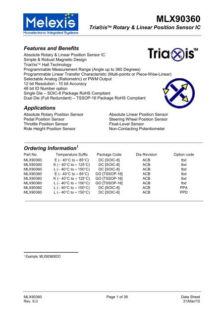
MLX90360
MLX90360
MLX90360

You also want an ePaper? Increase the reach of your titles
YUMPU automatically turns print PDFs into web optimized ePapers that Google loves.
<strong>MLX90360</strong><br />
Tria�is� Rotary & Linear Position Sensor IC<br />
Features and Benefits<br />
Absolute Rotary & Linear Position Sensor IC<br />
Simple & Robust Magnetic Design<br />
Tria�is� Hall Technology<br />
Programmable Measurement Range (Angle up to 360 Degrees)<br />
Programmable Linear Transfer Characteristic (Multi-points or Piece-Wise-Linear)<br />
Selectable Analog (Ratiometric) or PWM Output<br />
12 bit Resolution - 10 bit Accuracy<br />
48 bit ID Number option<br />
Single Die – SOIC-8 Package RoHS Compliant<br />
Dual Die (Full Redundant) – TSSOP-16 Package RoHS Compliant<br />
Applications<br />
Absolute Rotary Position Sensor Absolute Linear Position Sensor<br />
Pedal Position Sensor Steering Wheel Position Sensor<br />
Throttle Position Sensor Float-Level Sensor<br />
Ride Height Position Sensor Non-Contacting Potentiometer<br />
Ordering Information 1<br />
Part No. Temperature Suffix Package Code Die Revision Option code<br />
<strong>MLX90360</strong> E (� 40�C to � 85�C) DC [SOIC-8] ACB tbd<br />
<strong>MLX90360</strong> K (� 40�C to � 125�C) DC [SOIC-8] ACB tbd<br />
<strong>MLX90360</strong> L (� 40�C to � 150�C) DC [SOIC-8] ACB tbd<br />
<strong>MLX90360</strong> E (� 40�C to � 85�C) GO [TSSOP-16] ACB tbd<br />
<strong>MLX90360</strong> K (� 40�C to � 125�C) GO [TSSOP-16] ACB tbd<br />
<strong>MLX90360</strong> L (� 40�C to � 150�C) GO [TSSOP-16] ACB tbd<br />
<strong>MLX90360</strong> L (� 40�C to � 150�C) DC [SOIC-8] ACB PPA<br />
<strong>MLX90360</strong> L (� 40�C to � 150�C) DC [SOIC-8] ACB PPD<br />
1 Example: <strong>MLX90360</strong>EDC<br />
<strong>MLX90360</strong> Page 1 of 38 Data Sheet<br />
Rev. 6.0 31/Mar/10
1. Functional Diagram<br />
Tria�is<br />
VX<br />
VY<br />
VZ<br />
MUX<br />
G<br />
A<br />
D<br />
<strong>MLX90360</strong><br />
Tria�is� Rotary & Linear Position Sensor IC<br />
DSP<br />
ROM - F/W<br />
�C<br />
RAM<br />
EEP<br />
ROM<br />
<strong>MLX90360</strong> Page 2 of 38 Data Sheet<br />
Rev. 6.0 31/Mar/10<br />
VDIG<br />
3V3<br />
Reg<br />
Figure 1 - MLX 90360 Block Diagram<br />
D<br />
A<br />
Rev.Pol.<br />
&<br />
OverVolt.<br />
x 1<br />
VDD<br />
VSS<br />
OUT<br />
(Analog/PWM)
2. Description<br />
<strong>MLX90360</strong><br />
Tria�is� Rotary & Linear Position Sensor IC<br />
The <strong>MLX90360</strong> is a monolithic sensor IC featuring the Tria�is� Hall technology. Conventional planar Hall<br />
technology is only sensitive to the flux density applied orthogonally to the IC surface. The Tria�is� Hall<br />
sensor is also sensitive to the flux density applied parallel to the IC surface. This is obtained through an<br />
Integrated Magneto-Concentrator (IMC�) which is deposited on the CMOS die (as an additional back-end<br />
step).<br />
The <strong>MLX90360</strong> is part of the Gen. II of the Tria�is� Position Sensors Product Family.<br />
The <strong>MLX90360</strong> is sensitive to the three components of the flux density applied to the IC (i.e. BX, BY and<br />
BZ). This allows the <strong>MLX90360</strong> with the correct magnetic circuit to decode either the absolute rotary<br />
(angular - Figure 2) position from 0 to 360 Degrees or the absolute linear position (stroke - Figure 3). It<br />
enables the design of novel generation of non-contacting position sensors that are frequently required for<br />
both automotive and industrial applications.<br />
In combination with the appropriate signal processing, the magnetic flux density of a magnet moving<br />
above the IC can be measured in a non-contacting way. The position information (either angular or linear)<br />
is computed from two orthogonal vector components of the flux density, i.e. (BX,BY) or (BY,BZ) or (BX,BZ).<br />
<strong>MLX90360</strong> reports a programmable ratiometric analog output signal compatible with any resistive<br />
potentiometer or programmable linear Hall sensor. Through programming, the <strong>MLX90360</strong> provides also a<br />
digital PWM (Pulse Width Modulation) output characteristic.<br />
�<br />
Figure 2 - Typical application of <strong>MLX90360</strong> – Angular<br />
Figure 3 - Typical application of <strong>MLX90360</strong> – Linear<br />
<strong>MLX90360</strong> Page 3 of 38 Data Sheet<br />
Rev. 6.0 31/Mar/10
<strong>MLX90360</strong><br />
Tria�is� Rotary & Linear Position Sensor IC<br />
TABLE of CONTENTS<br />
FEATURES AND BENEFITS........................................................................................................................1<br />
APPLICATIONS ............................................................................................................................................1<br />
ORDERING INFORMATION.........................................................................................................................1<br />
1. FUNCTIONAL DIAGRAM ......................................................................................................................2<br />
2. DESCRIPTION .......................................................................................................................................3<br />
3. GLOSSARY OF TERMS � ABBREVIATIONS � ACRONYMS.............................................................6<br />
4. PINOUT ..................................................................................................................................................6<br />
5. ABSOLUTE MAXIMUM RATINGS........................................................................................................7<br />
6. DETAILED DESCRIPTION....................................................................................................................7<br />
7. <strong>MLX90360</strong> ELECTRICAL SPECIFICATION .......................................................................................11<br />
8. <strong>MLX90360</strong> ISOLATION SPECIFICATION ..........................................................................................14<br />
9. <strong>MLX90360</strong> TIMING SPECIFICATION .................................................................................................14<br />
10. <strong>MLX90360</strong> ACCURACY SPECIFICATION .........................................................................................15<br />
11. <strong>MLX90360</strong> MAGNETIC SPECIFICATION...........................................................................................16<br />
12. <strong>MLX90360</strong> CPU & MEMORY SPECIFICATION .................................................................................16<br />
13. <strong>MLX90360</strong> END-USER PROGRAMMABLE ITEMS ...........................................................................17<br />
14. DESCRIPTION OF END-USER PROGRAMMABLE ITEMS ..............................................................18<br />
14.1. OUTPUT MODE .........................................................................................................................................18<br />
14.1.1. Analog Output Mode............................................................................................................................18<br />
14.1.2. PWM Output Mode ..............................................................................................................................18<br />
14.2. OUTPUT TRANSFER CHARACTERISTIC ......................................................................................................19<br />
14.2.1. CLOCKWISE Parameter .....................................................................................................................19<br />
14.2.2. Discontinuity Point (or Zero Degree Point).........................................................................................20<br />
14.2.3. 3-Pts LNR Parameters .........................................................................................................................20<br />
14.2.4. 16-Pts LNR Parameters .......................................................................................................................21<br />
14.2.5. CLAMPING Parameters ......................................................................................................................22<br />
14.3. IDENTIFICATION........................................................................................................................................22<br />
14.4. SENSOR FRONT-END.................................................................................................................................22<br />
14.4.1. HIGHSPEED Parameter .....................................................................................................................22<br />
14.4.2. MAPXYZ and k Parameters .................................................................................................................22<br />
14.4.3. GAINMIN and GAINMAX Parameters ................................................................................................23<br />
14.5. FILTER ......................................................................................................................................................23<br />
14.5.1. Hysteresis Filter...................................................................................................................................23<br />
14.5.2. FIR Filters............................................................................................................................................24<br />
14.6. PROGRAMMABLE DIAGNOSTIC SETTINGS .................................................................................................25<br />
14.6.1. DIAG and ADIAG parameters .............................................................................................................25<br />
14.6.2. HAMHOLE Parameter.........................................................................................................................27<br />
<strong>MLX90360</strong> Page 4 of 38 Data Sheet<br />
Rev. 6.0 31/Mar/10
<strong>MLX90360</strong><br />
Tria�is� Rotary & Linear Position Sensor IC<br />
14.7. LOCK ........................................................................................................................................................27<br />
14.8. EEPROM ENDURANCE.............................................................................................................................27<br />
15. <strong>MLX90360</strong> SELF DIAGNOSTIC ..........................................................................................................28<br />
16. RECOMMENDED APPLICATION DIAGRAMS ..................................................................................30<br />
16.1. WIRING WITH THE <strong>MLX90360</strong> IN SOIC-8 PACKAGE – ANALOG OUTPUT ................................................30<br />
16.2. WIRING WITH THE <strong>MLX90360</strong> IN TSSOP-16 PACKAGE – ANALOG OUTPUT ...........................................30<br />
16.3. WIRING WITH THE <strong>MLX90360</strong> IN SOIC-8 PACKAGE – PWM OUTPUT.....................................................31<br />
16.4. WIRING WITH THE <strong>MLX90360</strong> IN TSSOP-16 PACKAGE – PWM OUTPUT................................................31<br />
17. STANDARD INFORMATION REGARDING MANUFACTURABILITY OF MELEXIS PRODUCTS<br />
WITH DIFFERENT SOLDERING PROCESSES ........................................................................................32<br />
18. ESD PRECAUTIONS ...........................................................................................................................32<br />
19. PACKAGE INFORMATION .................................................................................................................33<br />
19.1. SOIC8 - PACKAGE DIMENSIONS ...............................................................................................................33<br />
19.2. SOIC8 - PINOUT AND MARKING ...............................................................................................................33<br />
19.3. SOIC8 - IMC POSITIONNING ....................................................................................................................34<br />
19.4. TSSOP16 - PACKAGE DIMENSIONS ..........................................................................................................35<br />
19.5. TSSOP16 - PINOUT AND MARKING ..........................................................................................................36<br />
19.6. TSSOP16 - IMC POSITIONNING................................................................................................................36<br />
20. DISCLAIMER .......................................................................................................................................38<br />
<strong>MLX90360</strong> Page 5 of 38 Data Sheet<br />
Rev. 6.0 31/Mar/10
<strong>MLX90360</strong><br />
Tria�is� Rotary & Linear Position Sensor IC<br />
3. Glossary of Terms � Abbreviations � Acronyms<br />
� Gauss (G), Tesla (T): Units for the magnetic flux density � 1 mT = 10 G<br />
� TC: Temperature Coefficient (in ppm/Deg.C.)<br />
� NC: Not Connected<br />
� PWM: Pulse Width Modulation<br />
� %DC: Duty Cycle of the output signal i.e. TON /(TON + TOFF)<br />
� ADC: Analog-to-Digital Converter<br />
� DAC: Digital-to-Analog Converter<br />
� LSB: Least Significant Bit<br />
� MSB: Most Significant Bit<br />
� DNL: Differential Non-Linearity<br />
� INL: Integral Non-Linearity<br />
� RISC: Reduced Instruction Set Computer<br />
� ASP: Analog Signal Processing<br />
� DSP: Digital Signal Processing<br />
� ATAN: trigonometric function: arctangent (or inverse tangent)<br />
� IMC: Integrated Magneto-Concentrator (IMC�)<br />
� CoRDiC: Coordinate Rotation Digital Computer (i.e. iterative rectangular-to-polar transform)<br />
� EMC: Electro-Magnetic Compatibility<br />
� ALS: Analog Low Speed<br />
� AHS: Analog High Speed<br />
� DLS: Digital Low Speed<br />
� DHS: Digital High Speed<br />
4. Pinout<br />
Pin # SOIC-8 TSSOP-16<br />
1 VDD VDIG1<br />
2 Test 0 VSS1 (Ground1)<br />
3 Test 2 VDD1<br />
4 Not Used Test 01<br />
5 OUT Test 22<br />
6 Test 1 OUT2<br />
7 VDIG Not Used2<br />
8 VSS (Ground) Test 12<br />
9 VDIG2<br />
10 VSS2 (Ground2)<br />
11 VDD2<br />
12 Test 02<br />
13 Test 21<br />
14 Not Used1<br />
15 OUT1<br />
16<br />
Test 11<br />
For optimal EMC behavior, it is recommended to connect the unused pins (Not Used and Test) to the<br />
Ground (see section 16).<br />
<strong>MLX90360</strong> Page 6 of 38 Data Sheet<br />
Rev. 6.0 31/Mar/10
5. Absolute Maximum Ratings<br />
<strong>MLX90360</strong><br />
Tria�is� Rotary & Linear Position Sensor IC<br />
Parameter Value<br />
Supply Voltage, VDD (overvoltage) � 24 V<br />
Reverse Voltage Protection � 12 V (breakdown at -14 V)<br />
Positive Output Voltage � 18 V (breakdown at 24 V)<br />
Output Current (IOUT) � 30 mA (in breakdown)<br />
Reverse Output Voltage � 0.3 V<br />
Reverse Output Current � 50 mA (in breakdown)<br />
Operating Ambient Temperature Range, TA � 40°C � � 150�C<br />
Storage Temperature Range, TS � 40°C � � 150�C<br />
Magnetic Flux Density � 4 T<br />
Exceeding the absolute maximum ratings may cause permanent damage. Exposure to absolute<br />
maximum rated conditions for extended periods may affect device reliability.<br />
6. Detailed Description<br />
As described on the block diagram the three vector components of the magnetic flux density (BX, BY and<br />
BZ) applied to the IC are sensed through the Tria�is� sensor front-end. The respective Hall signals (VX,<br />
VY and VZ) are generated at the Hall plates and amplified.<br />
The analog signal processing is based on a fully differential analog chain featuring the classic offset<br />
cancellation technique (Hall plate 2-Phases spinning and chopper-stabilized amplifier).<br />
The conditioned analog signals are converted through an ADC (15 bits) and provided to a DSP block for<br />
further processing. The DSP stage is based on a 16 bit RISC micro-controller whose primary function is<br />
the extraction of the angular position from two (out of three) raw signals (after so-called front-end<br />
compensation steps) through the following function:<br />
� �<br />
�<br />
�Vk�� 1, V<br />
where V1 = VX or VY or VZ , V2 = VX or VY or VZ and k is a programmable factor to match the amplitude of<br />
V1 and k V2.<br />
The DSP functionality is governed by the micro-code (firmware � F/W) of the micro-controller which is<br />
stored into the ROM (mask programmable). In addition to the angle extraction, the F/W controls the whole<br />
analog chain, the output transfer characteristic, the output protocol, the programming/calibration and also<br />
the self-diagnostic modes.<br />
The angular information is intrinsically self-compensated vs. flux density variations (due to airgap change,<br />
thermal or ageing effects) affecting both arguments of the function. This feature allows therefore an<br />
improved thermal accuracy vs. rotary or linear position sensor based on conventional linear Hall sensors.<br />
In addition to the improved thermal accuracy, the realized rotary position sensor is capable of measuring a<br />
complete revolution (360 Degrees) and the linearity performances are excellent taking into account typical<br />
manufacturing tolerances (e.g. relative placement between the Hall IC and the magnet).<br />
<strong>MLX90360</strong> Page 7 of 38 Data Sheet<br />
Rev. 6.0 31/Mar/10<br />
2
<strong>MLX90360</strong><br />
Tria�is� Rotary & Linear Position Sensor IC<br />
Once the position (angular or linear stroke) information is computed, it is further conditioned (mapped) vs.<br />
the target transfer characteristic and it is provided at the output(s) as either a ratiometric analog output<br />
level through a 12 bit DAC followed by a buffer or a digital PWM output.<br />
For instance, the analog output can be programmed for offset, gain and clamping to meet any rotary<br />
position sensor output transfer characteristic:<br />
Vout(�) = ClampLo for � � �min<br />
Vout(�) = Voffset + Gain � � for �min � � � �max<br />
Vout(�) = ClampHi for � � �max<br />
where Voffset, Gain, ClampLo and ClampHi are the main adjustable parameters for the end-user.<br />
The linear part of the transfer curve can be adjusted through a multi-point calibration:<br />
This back-end step consists into either<br />
� up to 3 arbitrary points (4 segments + clamping levels) calibration or<br />
� a Piece-Wise-Linear (PWL) output transfer characteristics - 17 equidistant points w/<br />
programmable origin over 16 different angle ranges from 65 to 360 degrees.<br />
The calibration parameters are stored in EEPROM featuring a Hamming Error Correction Coding (ECC).<br />
The programming steps do not require any dedicated pins. The operation is done using the supply and<br />
output nodes of the IC. The programming of the <strong>MLX90360</strong> is handled at both engineering lab and<br />
production line levels by the Melexis Programming Unit PTC-04 with the dedicated <strong>MLX90360</strong><br />
daughterboard and software tools (DLL � User Interface).<br />
Application Example: Rotary Position Sensor<br />
While a magnet (diametrically magnetized) rotates above the IC as described on Figure 2, the magnetic<br />
flux densities along X and Y are in quadrature: BX � cos(�) & BY � sin(�) (Figure 4)<br />
<strong>MLX90360</strong> Page 8 of 38 Data Sheet<br />
Rev. 6.0 31/Mar/10
B X & B Y (G)<br />
400<br />
300<br />
200<br />
100<br />
0<br />
-100<br />
-200<br />
-300<br />
-400<br />
<strong>MLX90360</strong><br />
Tria�is� Rotary & Linear Position Sensor IC<br />
0 90 180 270 360 450 540 630 720<br />
Alpha (Degree)<br />
BX BY<br />
Figure 4 – Magnetic Flux Density – BX � cos(�) & BY � sin(�)<br />
The angular information will be computed using V1 = VY � BY and V2 = VX � BX and k � 1:<br />
� �<br />
Application Example: Linear Position Sensor<br />
�<br />
�B , B ����V, V �<br />
X<br />
Y<br />
While a bar-magnet moves above the IC as described on Figure3, the magnetic flux densities along Z and<br />
Y are shown on Figure 5.<br />
By & Bz [mT]<br />
80<br />
60<br />
40<br />
20<br />
0<br />
-20<br />
-40<br />
-60<br />
-80<br />
-10 0<br />
Displacement [mm]<br />
+10<br />
By Bz<br />
Figure 5 - Magnetic Flux Density – BZ & BY<br />
<strong>MLX90360</strong> Page 9 of 38 Data Sheet<br />
Rev. 6.0 31/Mar/10<br />
X<br />
Y
<strong>MLX90360</strong><br />
Tria�is� Rotary & Linear Position Sensor IC<br />
The position information will be computed using V1 = VY � BY and V2 = VZ � BZ and k < 1:<br />
�k�B, B ����k�VV� d � �<br />
,<br />
Note: d can actually been interpreted as the magnetic angle �YZ.<br />
Y<br />
Z<br />
<strong>MLX90360</strong> Page 10 of 38 Data Sheet<br />
Rev. 6.0 31/Mar/10<br />
Y<br />
Z
7. <strong>MLX90360</strong> Electrical Specification<br />
<strong>MLX90360</strong><br />
Tria�is� Rotary & Linear Position Sensor IC<br />
DC Operating Parameters at VDD = 5V (unless otherwise specified) and for TA as specified by the<br />
Temperature suffix (E or K or L).<br />
Parameter Symbol Test Conditions Min Typ Max Units<br />
Nominal Supply Voltage VDD 4.5 5 5.5 V<br />
Supply Current (2) Idd<br />
POR Rising Level POR LH<br />
POR Falling Level POR HL<br />
POR Hysteresis POR Hyst<br />
Slow mode (3)<br />
Fast mode (3)<br />
Supply Under Voltage<br />
In reference to On-chip digital voltage VDIG<br />
Supply Under Voltage<br />
In reference to On-chip digital voltage VDIG<br />
Hysteresis on POR signal<br />
In reference to On-chip digital voltage VDIG<br />
<strong>MLX90360</strong> Page 11 of 38 Data Sheet<br />
Rev. 6.0 31/Mar/10<br />
8.5<br />
13.5<br />
12<br />
15<br />
2.4 2.7 3<br />
2 2.3 2.6<br />
0.3 0.4 0.6<br />
ASP Start Rising Level LT4V LH Startup Level of ASP 3.5 4.1 V<br />
ASP Start Falling Level LT4V HL Startup Level of ASP 3.4 4 V<br />
ASP Start Hysteresis LT4V Hyst Startup Level of ASP 0.1 0.5 V<br />
PTC Entry Rising Level MT7V LH VDD level for PTC entry 6.6 7.2 V<br />
PTC Entry Falling Level MT7V HL VDD level for PTC entry 6.5 7.1 V<br />
PTC Entry Hysteresis MT7V Hyst VDD level for PTC entry 0.1 0.4 V<br />
Switch Off Rising Level LT11V LH 8.6 14 V<br />
Switch Off Falling Level LT11V HL 8.5 13.9 V<br />
Switch Off Level Hysteresis LT11 Hyst 0.1 1 V<br />
Output Current Iout Analog Output mode -15 15 mA<br />
Output Short Circuit Current Ishort<br />
Output Load RL<br />
Analog Saturation Output Level<br />
Active Diagnostic Output Level<br />
Vsat_lo<br />
Vsat_hi<br />
Diag_lo<br />
2 For the dual version, the supply current is multiplied by 2<br />
3 See section 9 for details concerning Slow and Fast mode<br />
Vout = 0 V<br />
Vout = 5 V<br />
Vout = 14 V (TA = 25°C)<br />
Pull-down to Ground<br />
Pull-up to 5V<br />
Pull-up load RL � 10 kΩ to 5 V<br />
Pull-up load RL � 1 kΩ to 5V<br />
Pull-up load RL � 5 kΩ to 14V<br />
Pull-down load RL � 5 kΩ<br />
Pull-down load RL � 10 kΩ<br />
Pull-down load RL � 10 kΩ<br />
Pull-down load RL � 5 kΩ<br />
1<br />
1<br />
94<br />
96<br />
10<br />
10<br />
0.5<br />
2<br />
2<br />
96<br />
98<br />
15<br />
15<br />
18<br />
�<br />
�<br />
2<br />
3<br />
3<br />
mA<br />
mA<br />
V<br />
V<br />
V<br />
mA<br />
mA<br />
mA<br />
k�<br />
k�<br />
%VDD<br />
%VDD<br />
1<br />
2 %VDD
Passive Diagnostic Output Level<br />
(Broken Track Diagnostic) (4)<br />
Clamped Output Level<br />
Diag_hi<br />
BVSSPD<br />
BVSSPU<br />
BVDDPD<br />
BVDDPU<br />
<strong>MLX90360</strong><br />
Tria�is� Rotary & Linear Position Sensor IC<br />
Pull-up load RL � 1 kΩ to 5V<br />
Pull-up load RL � 5 kΩ to 14V<br />
Pull-down load RL � 10kΩ<br />
Pull-down load RL � 5kΩ<br />
Pull-up load RL � 10 kΩ<br />
Broken VSS &<br />
Pull-down load RL ≤ 10 kΩ (Hi-Z)<br />
Pull-down load RL ≤ 25 kΩ (Hi-Z)<br />
Pull-down load RL � 50 kΩ (Hi-Z +<br />
PU on board)<br />
Broken VSS &<br />
Pull-up load RL � 1kΩ<br />
Broken VDD &<br />
Pull-down load RL � 1kΩ<br />
Broken VDD &<br />
Pull-up load RL ≤ 10kΩ (Hi-Z)<br />
<strong>MLX90360</strong> Page 12 of 38 Data Sheet<br />
Rev. 6.0 31/Mar/10<br />
96<br />
94<br />
98<br />
0<br />
0<br />
94<br />
2<br />
2<br />
98<br />
96<br />
3<br />
3<br />
4 (4)<br />
10<br />
100<br />
%VDD<br />
%VDD<br />
99 100 %VDD<br />
94<br />
0 1 %VDD<br />
100<br />
%VDD<br />
Clamp_lo Programmable 0 100 %VDD (5)<br />
Clamp_hi Programmable 0 100 %VDD (5)<br />
As an illustration of the previous table, the <strong>MLX90360</strong> fits the typical classification of the output span<br />
described on the Figure 6.<br />
4 For detailed information, see also section 15<br />
5 Clamping levels need to be considered vs the saturation of the output stage (see Vsat_lo and Vsat_hi)
Output Level<br />
100 %<br />
90 %<br />
80 %<br />
70 %<br />
60 %<br />
50 %<br />
40 %<br />
30 %<br />
20 %<br />
10 %<br />
0 %<br />
96 %<br />
92 %<br />
88 %<br />
12 %<br />
8 %<br />
4 %<br />
<strong>MLX90360</strong><br />
Tria�is� Rotary & Linear Position Sensor IC<br />
Clamping High<br />
Clamping Low<br />
Diagnostic Band (High)<br />
Linear Range<br />
Diagnostic Band (Low)<br />
Figure 6 – Example of Output Span Classification for typical application.<br />
<strong>MLX90360</strong> Page 13 of 38 Data Sheet<br />
Rev. 6.0 31/Mar/10
8. <strong>MLX90360</strong> Isolation Specification<br />
<strong>MLX90360</strong><br />
Tria�is� Rotary & Linear Position Sensor IC<br />
DC Operating Parameters at VDD = 5V (unless otherwise specified) and for TA as specified by the<br />
Temperature suffix (E or K or L). Only valid for the package code GO i.e. dual die version.<br />
Parameter Symbol Test Conditions Min Typ Max Units<br />
Isolation Resistance Between 2 dies 4 MΩ<br />
9. <strong>MLX90360</strong> Timing Specification<br />
DC Operating Parameters at VDD = 5V (unless otherwise specified) and for TA as specified by the<br />
Temperature suffix (E or K or L).<br />
Parameter Symbol Test Conditions Min Typ Max Units<br />
Main Clock Frequency Ck Slow mode (6)<br />
Fast mode (6)<br />
6.5<br />
MHz<br />
10.0<br />
MHz<br />
Main Clock Frequency Thermal<br />
Drift<br />
�TCk � 10% CkNOM<br />
Sampling Rate Slow mode (7)<br />
Fast mode (7)<br />
1000<br />
μs<br />
440<br />
μs<br />
Step Response Time Ts Slow mode (6) , Filter=0 (7)<br />
Slow mode (6) , Filter=2 (7)<br />
Fast mode (6) , Filter=0 (7)<br />
3<br />
ms<br />
6<br />
ms<br />
1.25 ms<br />
Watchdog Wd Slow Mode (Ck = 6 MHz)<br />
See Section 15<br />
4.58 ms<br />
Start-up Cycle Tsu Slow and Fast mode (6)<br />
Analog Output Slew Rate<br />
SlewRate effect excluded<br />
SlewRate effect included (see<br />
below)<br />
Mode 2<br />
up to COUT = 10 nF<br />
Mode 3<br />
up to COUT = 47 nF<br />
Mode 4<br />
up to COUT = 330 nF<br />
6 See section 13 for details concerning Slow and Fast mode activation<br />
7 See section 14.5 for details concerning Filter parameter<br />
<strong>MLX90360</strong> Page 14 of 38 Data Sheet<br />
Rev. 6.0 31/Mar/10<br />
320<br />
19<br />
2.5<br />
15<br />
20<br />
ms<br />
ms<br />
V/ms<br />
V/ms<br />
V/ms
10. <strong>MLX90360</strong> Accuracy Specification<br />
<strong>MLX90360</strong><br />
Tria�is� Rotary & Linear Position Sensor IC<br />
DC Operating Parameters at VDD = 5V (unless otherwise specified) and for TA as specified by the<br />
Temperature suffix (E or K or L).<br />
Parameter Symbol Test Conditions Min Typ Max Units<br />
ADC Resolution on the raw<br />
signals sine and cosine (8)<br />
RADC 15 bits<br />
Thermal Offset Drift #1 (9)<br />
Temperature suffix E<br />
-60<br />
+60 LSB15<br />
at the DSP input (excl. DAC and<br />
Temperature suffix K<br />
-60<br />
+60 LSB15<br />
output stage)<br />
Temperature suffix L<br />
-90<br />
+90 LSB15<br />
Thermal Offset Drift #2<br />
( DAC and Output Stage)<br />
-0.4 +0.4 %VDD<br />
Thermal Drift of Sensitivity<br />
Mismatch (10)<br />
XY axis - Temperature suffix E - 0.3<br />
+ 0.3 %<br />
XY axis - Temperature suffix K & L - 0.5<br />
+ 0.5 %<br />
XZ axis - Temperature suffix E -1<br />
+1 %<br />
XZ axis - Temperature suffix K & L -1<br />
+1 %<br />
XY - Intrinsic Linearity Error (11) Le TA = 25�C – factory trimmed “k” for<br />
X & Y<br />
-1 1 Deg<br />
XZ or YZ - Intrinsic Linearity<br />
Error (11)<br />
Le TA = 25�C – “k” not trimmed for XZ<br />
or YZ<br />
�2.5 Deg<br />
Analog Output Resolution RDAC 12b DAC (Theoretical, Noise free)<br />
0.025<br />
%VDD/LSB12<br />
INL (before EOL calibration)<br />
-4<br />
+4 LSB12<br />
DNL<br />
0.05 1 3 LSB12<br />
Output stage Noise Clamped Output 0.05 0.075 %VDD<br />
Noise pk-pk (12) Slow mode, Filter=2<br />
0.10 0.2 Deg<br />
Fast mode, Filter=0<br />
0.15 0.25 Deg<br />
Ratiometry Error (Analog output<br />
4.75 ≤ VDD ≤ 5.25<br />
-0.15<br />
+0.15 %VDD<br />
only)<br />
4.5V � VDD � 5.5V<br />
-0.25<br />
+0.25 %VDD<br />
LT4V � VDD � MT7V<br />
-1<br />
+1 %VDD<br />
8 16 bits corresponds to 15 bits + sign. Internal computation is performed using 16 bits.<br />
9 For instance, in case of a rotary position sensor application, Thermal Offset Drift #1 equal ± 60LSB15 yields to max. ± 0.3 Deg.<br />
angular error for the computed angular information (output of the DSP). This is only valid if k = 1. “<strong>MLX90360</strong> Front-End<br />
Application Note” will be released for more details.<br />
10 For instance, in case of a rotary position sensor application, Thermal Drift of Sensitivity Mismatch equal ± 0.5% yields to max.<br />
± 0.15 Deg. angular error for the computed angular information (output of the DSP). See “<strong>MLX90360</strong> Front-End Application Note”<br />
for more details.<br />
11 The Intrinsic Linearity Error refers to the IC itself (offset, sensitivity mismatch, orthogonality) taking into account an ideal<br />
rotating field for BX and BY. Once associated to a practical magnetic construction and the associated mechanical and magnetic<br />
tolerances, the output linearity error increases. However, it can be improved with the multi-point end-user calibration and/or “k”<br />
factor programming that are both available on the <strong>MLX90360</strong>. See “<strong>MLX90360</strong> Front-End Application Note” & “<strong>MLX90360</strong> Back-<br />
End Application Note” for more details.<br />
12 Noise pk-pk (peak-to-peak) is here intended as 6 times the Noise standard Deviation. The application diagram used is<br />
described in the recommended wiring. For detailed information, refer to section Filter in application mode (Section 14.5).<br />
<strong>MLX90360</strong> Page 15 of 38 Data Sheet<br />
Rev. 6.0 31/Mar/10
11. <strong>MLX90360</strong> Magnetic Specification<br />
<strong>MLX90360</strong><br />
Tria�is� Rotary & Linear Position Sensor IC<br />
DC Operating Parameters at VDD = 5V (unless otherwise specified) and for TA as specified by the<br />
Temperature suffix (E or K or L).<br />
Parameter Symbol Test Conditions Min Typ Max Units<br />
Magnetic Flux Density BX, BY 20 50 70 (13) mT<br />
Magnetic Flux Density BZ 24 75 126 mT<br />
Magnet Temperature Coefficient TCm -2400 0 ppm/°C<br />
IMC Gain (14) GainIMC 1.2 1.5 1.8<br />
12. <strong>MLX90360</strong> CPU & Memory Specification<br />
The DSP is based on a 16 bit RISC µController. This CPU provides 2.5 Mips while running at 10 MHz.<br />
Parameter Symbol Test Conditions Min Typ Max Units<br />
ROM 7 kB<br />
RAM 256 B<br />
EEPROM 128 B<br />
13 Above 70 mT, the IMC starts saturating yielding to an increase of the linearity error. Below 20 mT, the performances slightly<br />
degrade due to a reduction of the signal-to-noise ratio, signal-to-offset ratio…<br />
14 This is the magnetic gain linked to the Integrated Magneto Concentrator structure. It applies to BX and BY and not to BZ. This is<br />
the overall variation. Within one lot, the part to part variation is typically ± 10% versus the average value of the IMC gain of that<br />
lot.<br />
<strong>MLX90360</strong> Page 16 of 38 Data Sheet<br />
Rev. 6.0 31/Mar/10
13. <strong>MLX90360</strong> End-User Programmable Items<br />
<strong>MLX90360</strong><br />
Tria�is� Rotary & Linear Position Sensor IC<br />
Parameter Comments<br />
Default Values<br />
Standard PPAR PPDR Free # bit<br />
Output mode Define the output stage mode 4h 1h 7h 3<br />
DIAG Diagnostic mode (Low/Hi) 0h 0h 0h 1<br />
ADIAG Analog diagnostic option (Low/Hiz or HiZ/Hi) 0h 0h 0h 1<br />
HS High speed mode (6MHz or 10MHz) 0h 0h 1h 1<br />
MAPXYZ Mapping fields for output angle MLX MLX MLX 3<br />
CLAMP_HIGH Clamping High (50%) 7FFFh 7FFFh 7FFFh 16<br />
CLAMP_LOW Clamping Low (50%) 7FFFh 7FFFh 7FFFh 16<br />
FILTERFIRST Filtering before linear correction 0h 1h 1h 1<br />
FILTER Filter mode selection 0h 1h 2h 2<br />
k (SMISM) Sensitivity mismatch factor FFFFh FFFFh FFFFh 16<br />
GAINMIN Low threshold for virtual gain 00h 00h 00h 8<br />
GAINMAX High threshold for virtual gain 29h 29h 29h 8<br />
PWMPOL PWM polarity 0h 0h 0h 1<br />
PWMT PWM Frequency (for 1kHz) 1B58h 1B58h 1B58h 16<br />
DP Discontinuity point 0000h 0000h 0000h 15<br />
CCW Counter Clock Wise 0h 0h 0h 1<br />
FHYST Hysteresis filter<br />
0h 0h 0h 8<br />
MELEXISID1 Melexis identification reference MLX MLX MLX 16<br />
MELEXISID2 Melexis identification reference MLX MLX MLX 16<br />
MELEXISID3 Melexis identification reference MLX MLX MLX 16<br />
CUSTUMERID1 Customer identification reference 0h 1 2 16<br />
CUSTUMERID2 Customer identification reference 0h 0h 0h 16<br />
CUSTUMERID3 Customer identification reference 0h 0h 0h 16<br />
CUSTUMERID4 Customer identification reference 0h 0h 0h 16<br />
3POINTS Selection of correction method 3 or 16 pts 1h 1h 1h 1<br />
LNR_S0 3pts – Initial Slope 0h 0h 0h 16<br />
LNR_A_X 3pts – AX Coordinate 7FFFh 7FFFh 7FFFh 16<br />
LNR_A_Y 3pts – AY Coordinate 0 0 0 16<br />
LNR_A_S 3pts – AS Coordinate 0 80%/360d 80%/360d 16<br />
LNR_B_X 3pts – BX Coordinate FFFFh FFFFh FFFh 16<br />
LNR_B_Y 3pts – BY Coordinate 0 0 0 16<br />
LNR_B_S 3pts – BS Coordinate 0 0 0 16<br />
LNR_C_X 3pts – CX Coordinate FFFFh FFFFh FFFFh 16<br />
LNR_C_Y 3pts – CY Coordinate FFFFh FFFFh FFFFh 16<br />
LNR_C_S 3pts – CS Coordinate 0 0 0 16<br />
W 16pts – Output angle range 0h 0h 0h 4<br />
LNR_Y0 16pts – Y-coordinate point 0 N/A N/A N/A 16<br />
LNR_Y16 16pts – Y-coordinate point 16 N/A N/A N/A 16<br />
HAMHOLE Hamming code recovery 3131h 3131h 3131h 16<br />
LOCK Lock byte 00h 00h 00h 8<br />
<strong>MLX90360</strong> Page 17 of 38 Data Sheet<br />
Rev. 6.0 31/Mar/10
<strong>MLX90360</strong><br />
Tria�is� Rotary & Linear Position Sensor IC<br />
14. Description of End-User Programmable Items<br />
14.1. Output Mode<br />
The <strong>MLX90360</strong> output type is defined by the Output Mode parameter.<br />
Parameter Value Description<br />
Analog Output Mode<br />
PWM Output Mode<br />
14.1.1. Analog Output Mode<br />
2<br />
3<br />
4<br />
5<br />
6<br />
7<br />
Analog Rail-to-Rail for Coutmax = 10nF<br />
Analog Rail-to-Rail for Coutmax = 68nF<br />
Analog Rail-to-Rail for Coutmax = 330nF<br />
Low Side (NMOS)<br />
High Side (PMOS)<br />
Push-Pull<br />
The Analog Output Mode is a rail-to-rail and ratiometric output with a push-pull output stage configuration<br />
allows the use of a pull-up or pull-down resistor.<br />
14.1.2. PWM Output Mode<br />
If PWM output mode is selected, the output signal is a digital signal with Pulse Width Modulation (PWM).<br />
The PWM polarity is selected by the PWMPOL1 parameter:<br />
� PWMPOL = 0 for a low level at 100%<br />
� PWMPOL = 1 for a high level at 100%<br />
The PWM frequency is selected by the PWMT parameter. The following table provides typical code for<br />
different target PWM frequency and for both low and high speed modes.<br />
Notes:<br />
PWM Frequency Code (PWMT)<br />
Oscillator Mode<br />
Pulse-Width Modulation Frequency (Hz)<br />
100 200 500 1000<br />
Low Speed (CkNOM = 6.5 MHz) 32500 16250 6500 3250<br />
High Speed (CkNOM = 10 MHz) 50000 25000 10000 5000<br />
� A more accurate trimming can be performed to take into account initial tolerance of the main<br />
clock.<br />
� The PWM frequency is subjected to the same tolerances as the main clock (see � T Ck).<br />
<strong>MLX90360</strong> Page 18 of 38 Data Sheet<br />
Rev. 6.0 31/Mar/10
14.2. Output Transfer Characteristic<br />
There are 2 different possibilities to define the transfer function (LNR):<br />
<strong>MLX90360</strong><br />
Tria�is� Rotary & Linear Position Sensor IC<br />
� With 3 arbitrary points (defined on X and Y coordinates) and 4 slopes<br />
� With 16 equidistant points for which only the Y coordinates are defined.<br />
Parameter LNR type Value Unit<br />
CLOCKWISE Both<br />
0 � CCW<br />
1 � CW<br />
DP Both 0 � 359.9999 deg<br />
LNR_A_X<br />
LNR_B_X<br />
LNR_C_X<br />
LNR_A_Y<br />
LNR_B_Y<br />
LNR_C_Y<br />
LNR_S0<br />
LNR_A_S<br />
LNR_B_S<br />
Only 3 pts 0 � 359.9999 deg<br />
Only 3 pts 0 � 100 %<br />
Only 3 pts 0 � 17 %/deg<br />
LNR_C_S Only 3 pts -17 … 0 … 17 %/deg<br />
LNR_Y0<br />
LNR_Y1<br />
…<br />
LNR_Y16<br />
Only 16 pts -50 … + 150 %<br />
W Only 16 pts 65 … 360 Deg<br />
CLAMP_LOW Both 0 � 100 %<br />
CLAMP_HIGH Both 0 � 100 %<br />
14.2.1. CLOCKWISE Parameter<br />
The CLOCKWISE parameter defines the magnet rotation direction.<br />
� CCW is the defined by the 1-4-5-8 pin order direction for the SOIC8 package and 1-8-9-16 pin<br />
order direction for the TSSOP16 package.<br />
� CW is defined by the reverse direction: 8-5-4-1 pin order direction for the SOIC8 and 16-9-8-1 pin<br />
order direction for the TSSOP16 package.<br />
Refer to the drawing in the IMC positioning sections (Section 19.3)<br />
<strong>MLX90360</strong> Page 19 of 38 Data Sheet<br />
Rev. 6.0 31/Mar/10
14.2.2. Discontinuity Point (or Zero Degree Point)<br />
<strong>MLX90360</strong><br />
Tria�is� Rotary & Linear Position Sensor IC<br />
The Discontinuity Point defines the 0° point on the circle. The discontinuity point places the origin at any<br />
location of the trigonometric circle. The DP is used as reference for all the angular measurements.<br />
0°<br />
14.2.3. 3-Pts LNR Parameters<br />
360°<br />
The placement of the discontinuity<br />
point (0 point) is programmable.<br />
Figure 7 - Discontinuity Point Positioning<br />
The LNR parameters, together with the clamping values, fully define the relation (the transfer function)<br />
between the digital angle and the output signal.<br />
The shape of the <strong>MLX90360</strong> transfer function from the digital angle value to the output voltage is<br />
described by the drawing below. Six segments can be programmed but the clamping levels are<br />
necessarily flat.<br />
Two, three, or even five calibration points are then available, reducing the overall non-linearity of the IC by<br />
almost an order of magnitude each time. Three or five point calibration will be preferred by customers<br />
looking for excellent non-linearity figures. Two-point calibrations will be preferred by customers looking for<br />
a cheaper calibration set-up and shorter calibration time.<br />
100 %<br />
CLAMPHIGH<br />
LNR_C_Y<br />
LNR_B_Y<br />
LNR_A_Y<br />
CLAMPLOW<br />
0 %<br />
0<br />
Clamping High<br />
A<br />
LNR_A_X<br />
Slope LNR_S0<br />
B<br />
Slope LNR_A_S<br />
<strong>MLX90360</strong> Page 20 of 38 Data Sheet<br />
Rev. 6.0 31/Mar/10<br />
C<br />
LNR_B_X LNR_C_X<br />
Figure 8<br />
Slope LNR_B_S<br />
Slope LNR_C_S<br />
Clamping Low<br />
360<br />
(Deg.)
14.2.4. 16-Pts LNR Parameters<br />
<strong>MLX90360</strong><br />
Tria�is� Rotary & Linear Position Sensor IC<br />
The LNR parameters, together with the clamping values, fully define the relation (the transfer function)<br />
between the digital angle and the output signal.<br />
The shape of the MLX90316 transfer function from the digital angle value to the output voltage is<br />
described by the drawing below. In the 16-Pts mode, the output transfer characteristic is Piece-Wise-<br />
Linear (PWL).<br />
Figure 9 - Input range from 65.5° up to 360°<br />
All the Y-coordinates can be programmed from -50% up to +150% to allow clamping in the middle of one<br />
segment (like on the figure), but the output value is limited to CLAMPLOW and CLAMPHIGH values.<br />
Between two consecutive points, the output characteristic is interpolated.<br />
The parameter W determines the input range on which the 17 points (16 segments) are uniformly spread:<br />
W Range �x � W Range �x<br />
0 (0000b) 360.0deg 22.5deg 8 180.0deg 11.3deg<br />
1 320.0deg 20.0deg 9 144.0deg 9.0deg<br />
2 288.0deg 18.0deg 10 120.0deg 7.5deg<br />
3 261.8deg 16.4deg 11 102.9deg 6.4deg<br />
4 240.0deg 15.0deg 12 90.0deg 5.6deg<br />
5 221.5deg 13.8deg 13 80.0deg 5.0deg<br />
6 205.7deg 12.9deg 14 72.0deg 4.5deg<br />
7 192.0deg 12.0deg<br />
15<br />
(1111b)<br />
65.5deg 4.1deg<br />
<strong>MLX90360</strong> Page 21 of 38 Data Sheet<br />
Rev. 6.0 31/Mar/10
14.2.5. CLAMPING Parameters<br />
<strong>MLX90360</strong><br />
Tria�is� Rotary & Linear Position Sensor IC<br />
The clamping levels are two independent values to limit the output voltage range. The CLAMPLOW<br />
parameter adjusts the minimum output voltage level. The CLAMPHIGH parameter sets the maximum<br />
output voltage level. Both parameters have 16 bits of adjustment and are available for both LNR modes.<br />
In analog mode, the resolution will be limited by the D/A converter (12 bits) to 0.024%VDD. In PWM mode,<br />
the resolution will be 0.024%DC.<br />
14.3. Identification<br />
Parameter Value<br />
MELEXSID1<br />
MELEXSID2<br />
MELEXSID3<br />
CUSTOMERID1<br />
CUSTOMERID2<br />
CUSTOMERID3<br />
0 � 65535<br />
0 � 65535<br />
0 � 65535<br />
0 � 65535<br />
0 � 65535<br />
0 � 65535<br />
Identification number: 48 bits (3 words) freely useable by Customer for traceability purpose.<br />
Those 48 bits are only available if the 3pts-LNR. For the 16-Pts LNR, the corresponding EEPROM area is<br />
used by the LNR function.<br />
14.4. Sensor Front-End<br />
14.4.1. HIGHSPEED Parameter<br />
Parameter Value<br />
HS<br />
0 = Slow mode<br />
1 = Fast mode<br />
MAPXYZ 0 .. 5<br />
k (or SMISM) 0 .. 65535<br />
GAINMIN<br />
GAINMAX<br />
0 � 41<br />
The HIGHSPEED parameter defines the main frequency for the DSP.<br />
� HIGHSPEED = 0 selects the Slow mode with a 6.5 MHz master clock (nominal).<br />
� HIGHSPEED = 1 selects the Fast mode with a 10.0 MHz master clock (nominal).<br />
For better noise performance, the Slow Mode must be enabled.<br />
14.4.2. MAPXYZ and k Parameters<br />
The MAPXYZ parameter defines which fields are used to calculate the angle. The different possibilities<br />
are described in the tables below.<br />
<strong>MLX90360</strong> Page 22 of 38 Data Sheet<br />
Rev. 6.0 31/Mar/10
<strong>MLX90360</strong><br />
Tria�is� Rotary & Linear Position Sensor IC<br />
MAPXYZ Angle definition<br />
0 � XY � ��k�B,<br />
�<br />
X BY<br />
1 � YX � ��B,<br />
k � B �<br />
2 � XZ � ��k�B,<br />
�<br />
<strong>MLX90360</strong> Page 23 of 38 Data Sheet<br />
Rev. 6.0 31/Mar/10<br />
X<br />
Y<br />
X BZ<br />
3 � ZX � ��B,<br />
k � B �<br />
4 � YZ � ��k�B,<br />
�<br />
Z<br />
Z<br />
Y BZ<br />
5 � ZY � ��B,<br />
k � B �<br />
The k parameter defines the sensitivity mismatch between the 2 selected axis used for the angular<br />
calculation. Its value is defined through an unsigned 16 bits value from 0.0 to 1.0. The values from 0.5 up<br />
to 1 are supposed to be used.<br />
14.4.3. GAINMIN and GAINMAX Parameters<br />
GAINMIN and GAINMAX define the boundaries within the virtual gain setting is allowed to vary. Outside<br />
this range, the output is set in diagnostic mode.<br />
14.5. Filter<br />
The MLX90316 includes 2 types of filters:<br />
Parameter Value<br />
FILTER 0 � 3<br />
FHYST 0 � 31<br />
FILTERFIRST 0 or 1<br />
� Hysteresis Filter: programmable by the FHYST parameter<br />
� Low Pass FIR Filters controlled with the FILTER parameter<br />
Note: if the parameter FILTERFIRST is set to “1”, the filtering is active on the digital angle (prior to the<br />
output mapping). If set to “0”, the filtering is active on the output transfer function (after the output<br />
mapping).<br />
14.5.1. Hysteresis Filter<br />
The FHYST parameter is a hysteresis filter. The output value of the IC is not updated when the digital step<br />
is smaller than the programmed FHYST parameter value. The output value is modified when the<br />
increment is bigger than the hysteresis. The hysteresis filter reduces therefore the resolution to a level<br />
compatible with the internal noise of the IC. The hysteresis must be programmed to a value close to the<br />
noise level.<br />
Y<br />
Z
14.5.2. FIR Filters<br />
<strong>MLX90360</strong><br />
Tria�is� Rotary & Linear Position Sensor IC<br />
The <strong>MLX90360</strong> features 3 FIR filter modes controlled with Filter = 1…3. Filter = 0 corresponds to no<br />
filtering. The transfer function is described below:<br />
1<br />
yn � j<br />
� ai<br />
i�0<br />
j<br />
� aix<br />
n�i<br />
i�0<br />
The characteristics of the filters 0 to 3 is given in the following table.<br />
30000<br />
20000<br />
Digital value<br />
[16bits]<br />
10000<br />
0<br />
Filter No (j) 0 1 2 3<br />
Type Disable Finite Impulse Response<br />
Coefficients ai 1 11 1111 12221<br />
Title No filter ExtraLight Light Medium<br />
99% Response Time 1 2 4 5<br />
Efficiency RMS (dB) 0 3.0 6.0 6.6<br />
No filtering FIR1 [11]<br />
FIR2 [1111] FIR2 [12221]<br />
0 10 20 Time [samples] 30 40 50<br />
Figure 10 - Step and impulse response of the different filters<br />
<strong>MLX90360</strong> Page 24 of 38 Data Sheet<br />
Rev. 6.0 31/Mar/10
50000<br />
Digital value<br />
[16bits]<br />
40000<br />
<strong>MLX90360</strong><br />
Tria�is� Rotary & Linear Position Sensor IC<br />
No filtering FIR1 [11]<br />
FIR2 [1111] FIR2 [12221]<br />
0 10 20 Time [samples] 30 40 50<br />
14.6. Programmable Diagnostic Settings<br />
14.6.1. DIAG and ADIAG parameters<br />
Figure 11 - Noise response of the different filter<br />
Parameter Value Unit<br />
DIAG 0 or 1<br />
ADIAG 0 or 1<br />
HAMHOLE 0 or 3131h<br />
When analog mode is selected, DIAG and ADIAG allow selecting all diagnostic modes:<br />
Mode Type Description<br />
With pull-up<br />
DIAG = 0 Diagnostic Low<br />
ADIAG = 0<br />
DIAG = 1 Diagnostic Hi (HiZ + pull-up)<br />
With pull-down<br />
DIAG = 0 Diagnostic Low (HiZ + pull-down)<br />
ADIAG = 1<br />
DIAG = 1 Diagnostic Hi<br />
<strong>MLX90360</strong> Page 25 of 38 Data Sheet<br />
Rev. 6.0 31/Mar/10
For digital mode, only DIAG is used:<br />
<strong>MLX90360</strong><br />
Tria�is� Rotary & Linear Position Sensor IC<br />
Digital mode Type Description<br />
5 – Open drain NMOS<br />
6 – Open drain PMOS<br />
7 – Push-pull output<br />
LT11V<br />
MT7V<br />
4.5-5.5V<br />
Pull-Down<br />
Pull-Up<br />
LT4V<br />
POR<br />
Pull-Up<br />
Voltage<br />
Pull-Up<br />
Voltage<br />
DIAG = 0<br />
DIAG = 1<br />
DIAG = 0<br />
DIAG = 1<br />
DIAG = 0<br />
DIAG = 1<br />
Diagnostic Low<br />
Diagnostic Hi (HiZ + pull-up)<br />
Diagnostic Low (HiZ + pull-down)<br />
Diagnostic Hi<br />
Diagnostic Low<br />
Diagnostic Hi<br />
Diagnostic<br />
No Diagnostic<br />
EE_DIAG = 1<br />
EE_DIAG = 0<br />
EE_DIAG = 1<br />
EE_DIAG = 0<br />
Figure 12 - Output voltage in diagnostic modes over supply voltage.<br />
<strong>MLX90360</strong> Page 26 of 38 Data Sheet<br />
Rev. 6.0 31/Mar/10
14.6.2. HAMHOLE Parameter<br />
<strong>MLX90360</strong><br />
Tria�is� Rotary & Linear Position Sensor IC<br />
The HAMHOLE parameter disables the memory recovery (Hamming code) check when a fault is detected<br />
by the CRC when it is equal to 3131h. By default the parameter is set to 3131h (enable memory<br />
recovery).<br />
14.7. Lock<br />
The LOCK parameter locks all the parameters set by the user. Once the lock is enabled, it is not possible<br />
to change the EEPROM values anymore as PTC communication in writing mode is not available<br />
anymore.<br />
Note that the lock bit should be set by the solver function “MemLock”.<br />
14.8. EEPROM endurance<br />
Although the EEPROM is used for Calibration Data Storage (similarly to an OTPROM), the <strong>MLX90360</strong><br />
embedded EEPROM is qualified to guarantee an endurance of minimum 1000 write cycles at 125˚C for<br />
(engineering/calibration purpose).<br />
<strong>MLX90360</strong> Page 27 of 38 Data Sheet<br />
Rev. 6.0 31/Mar/10
15. <strong>MLX90360</strong> Self Diagnostic<br />
<strong>MLX90360</strong><br />
Tria�is� Rotary & Linear Position Sensor IC<br />
The <strong>MLX90360</strong> provides numerous self-diagnostic features. Those features increase the robustness of the IC<br />
functionality as it will prevent the IC to provide erroneous output signal in case of internal or external failure<br />
modes (“fail-safe”).<br />
Action Effect on Outputs Remark<br />
ROM CRC Error at start up CPU Reset<br />
(64 words including Intelligent<br />
Watch Dog - IWD)<br />
(15) Diagnostic low/high (16) All the outputs are already<br />
in Diagnostic low/high -<br />
(start-up)<br />
ROM CRC Error (Operation - Enter Endless Loop:<br />
Immediate Diagnostic<br />
Background task)<br />
- Progress (watchdog<br />
Acknowledge)<br />
- Set Outputs in Diagnostic<br />
low/high<br />
low//high (16)<br />
RAM Test Fail (Start up) CPU Reset Diagnostic low/ high (16) All the outputs are already<br />
in Diagnostic low/high<br />
(start-up)<br />
Calibration Data CRC Error Hamming Code Recovery Start-Up Time is increased<br />
(Start-Up)<br />
by 3 ms if successful<br />
recovery<br />
Hamming Code Recovery Error<br />
(Start-Up)<br />
CPU Reset Diagnostic low/high (16) See section HAMHOLE<br />
Calibration Data CRC Error<br />
(Operation - Background)<br />
ADC Clipping<br />
(ADC Output is 0000h or<br />
7FFFh)<br />
Norm Too Low<br />
( < 25 % )<br />
Rough Offset Clipping<br />
(RO is = 0d or = 127d)<br />
Gain Clipping<br />
(Gain < GAINMIN or Gain ><br />
GAINMAX)<br />
<strong>MLX90360</strong> Fault Mode continues…<br />
CPU Reset Diagnostic low/high (16)<br />
Set Outputs in Diagnostic low/high<br />
Normal mode and CPU Reset If<br />
recovery<br />
Set Outputs in Diagnostic low/high<br />
Normal mode and CPU Reset If<br />
recovery<br />
Set Outputs in Diagnostic low/high<br />
Normal mode, with immediate<br />
recovery without CPU reset<br />
Set Outputs in Diagnostic low/high<br />
Normal mode, and CPU Reset If<br />
recovery<br />
Immediate Diagnostic<br />
low/high (16)<br />
Immediate Diagnostic<br />
low/high (16)<br />
Immediate Diagnostic<br />
low/high (16)<br />
Immediate Diagnostic<br />
low/high (16)<br />
15 CPU reset means<br />
1. Core Reset (same as Power-On-Reset). It induces a typical start up time.<br />
2. Periphery Reset (same as Power-On-Reset)<br />
3. Fault Flag/Status Lost<br />
If no magnet IC in Diag.<br />
mode.<br />
See also Section GAINMIN<br />
and GAINMAX.<br />
<strong>MLX90360</strong> Page 28 of 38 Data Sheet<br />
Rev. 6.0 31/Mar/10
<strong>MLX90360</strong><br />
Tria�is� Rotary & Linear Position Sensor IC<br />
…<strong>MLX90360</strong> Fault Mode<br />
Fault Mode Action Effect on Outputs Remark<br />
ADC Monitor (Analog to Digital<br />
Converter)<br />
Set Outputs in Diagnostic low/high.<br />
Normal Mode with immediate<br />
recovery without CPU Reset<br />
Undervoltage Mode At Start-Up, wait Until VDD > LT4V.<br />
During operation, CPU Reset after<br />
3 ms debouncing.<br />
Immediate Diagnostic<br />
low/high (16)<br />
- VDD < POR level<br />
=> Output high impedance<br />
- POR level < VDD < ~LT4V<br />
=> Output in Diagnostic<br />
low/high (16) .<br />
Firmware Flow Error CPU Reset Immediate Diagnostic<br />
low/high (16)<br />
Read/Write Access out of CPU Reset Immediate Diagnostic<br />
physical memory<br />
low/high (16)<br />
Write Access to protected area CPU Reset Immediate Diagnostic<br />
(IO and RAM Words)<br />
low/high (16)<br />
Unauthorized entry in<br />
CPU Reset Immediate Diagnostic<br />
“SYSTEM” Mode<br />
low/high (16)<br />
VDD > MT7V Set Output High Impedance<br />
Pull down resistive load =><br />
(Analog)<br />
Diag. Low<br />
Pull up resistive load =><br />
Diag. High<br />
VDD > LT11V IC is switched off (internal supply) Pull down resistive load =><br />
CPU Reset on recovery<br />
Diag. Low<br />
Pull up resistive load =><br />
Diag. High<br />
Broken VSS CPU Reset on recovery Pull down resistive load <<br />
10k� => Diag. Low<br />
Pull up resistive load (any<br />
value) => Diag. High<br />
Broken VDD CPU Reset on recovery Pull down resistive load (any<br />
value) => Diag. Low<br />
Pull up resistive load < 10k�<br />
=> Diag. High<br />
Temperature Monitor<br />
Set Outputs in Diagnostic low/high. Immediate Diagnostic<br />
Normal Mode with immediate<br />
recovery without CPU Reset<br />
low/high (16)<br />
ADC Inputs are Shorted<br />
and connected to Vref. ADC<br />
output is compared to a<br />
fixed value.<br />
Intelligent Watchdog<br />
(Observer)<br />
100% Hardware detection<br />
100% Hardware detection<br />
100% Hardware detection<br />
100% Hardware detection<br />
100% Hardware detection<br />
100% Hardware detection<br />
100% Hardware detection<br />
Temperature Sensor 1 is<br />
compared to temperature<br />
sensor 2<br />
16 The diagnostics can be selectable between Diagnostic Low/Diagnostic High by setting the bits EE_DIAG and EE_ADIAG (for<br />
analog modes only). See section Programmable Diagnostic Settings for the Diagnostic Output Level specifications.<br />
<strong>MLX90360</strong> Page 29 of 38 Data Sheet<br />
Rev. 6.0 31/Mar/10
16. Recommended Application Diagrams<br />
<strong>MLX90360</strong><br />
Tria�is� Rotary & Linear Position Sensor IC<br />
16.1. Wiring with the <strong>MLX90360</strong> in SOIC-8 Package – Analog Output<br />
1<br />
4<br />
Vdd<br />
Vss<br />
<strong>MLX90360</strong><br />
Test 0 Vdig<br />
Test 2<br />
NotUsed<br />
Test 1<br />
Out<br />
8<br />
5<br />
C1<br />
100nF<br />
C2<br />
100nF<br />
C3<br />
100nF<br />
<strong>MLX90360</strong> Page 30 of 38 Data Sheet<br />
Rev. 6.0 31/Mar/10<br />
Vdd<br />
GND<br />
Output<br />
R1<br />
10K<br />
5 V<br />
C4<br />
4.7nF<br />
ECU<br />
Figure 13 – Recommended wiring for the <strong>MLX90360</strong> in SOIC8 package - Analog.<br />
16.2. Wiring with the <strong>MLX90360</strong> in TSSOP-16 Package – Analog Output<br />
C1<br />
100nF<br />
C6<br />
100nF<br />
C2<br />
100nF<br />
1<br />
8<br />
Vdig1<br />
Vss1<br />
Vdd1<br />
Out2<br />
<strong>MLX90360</strong><br />
GND1<br />
Out1<br />
Vdd2<br />
Vss2<br />
Vdig2<br />
GND2<br />
16<br />
9<br />
C5<br />
100nF<br />
C3<br />
100nF<br />
C4<br />
100nF<br />
Vdd1<br />
GND1<br />
Output1<br />
Vdd2<br />
GND2<br />
Output2<br />
Figure 14 – Recommended wiring for the <strong>MLX90360</strong> in TSSOP16 package (dual die) - Analog.<br />
R1<br />
10K<br />
R2<br />
10K<br />
VDD2<br />
VDD1<br />
C7<br />
4.7nF<br />
C8<br />
4.7nF<br />
ADC<br />
ECU<br />
GND1<br />
GND2<br />
ADC
<strong>MLX90360</strong><br />
Tria�is� Rotary & Linear Position Sensor IC<br />
16.3. Wiring with the <strong>MLX90360</strong> in SOIC-8 Package – PWM Output<br />
1<br />
8<br />
Vdd<br />
Vss<br />
<strong>MLX90360</strong><br />
Test 0 Vdig<br />
4<br />
Test 2<br />
NotUsed<br />
Test 1<br />
Out<br />
5<br />
C1<br />
100nF<br />
C2<br />
100nF<br />
C3<br />
4.7nF<br />
<strong>MLX90360</strong> Page 31 of 38 Data Sheet<br />
Rev. 6.0 31/Mar/10<br />
Vdd<br />
GND<br />
Output<br />
R1<br />
10k<br />
5 V<br />
C4<br />
4.7nF<br />
ECU<br />
Figure 15 – Recommended wiring for the <strong>MLX90360</strong> in SOIC8 package - PWM.<br />
16.4. Wiring with the <strong>MLX90360</strong> in TSSOP-16 Package – PWM Output<br />
C1<br />
100nF<br />
C6<br />
4.7nF<br />
C2<br />
100nF<br />
1<br />
Vdig1<br />
Vss1<br />
Vdd1<br />
8<br />
Out2<br />
<strong>MLX90360</strong><br />
GND1<br />
Out1<br />
Vdd2<br />
Vss2<br />
Vdig2<br />
GND2<br />
16<br />
9<br />
C5<br />
100nF<br />
C3<br />
4.7nF<br />
C4<br />
100nF<br />
Vdd1<br />
GND1<br />
Output1<br />
Vdd2<br />
GND2<br />
Output2<br />
Figure 16 – Recommended wiring for the <strong>MLX90360</strong> in TSSOP16 package (dual die) - PWM.<br />
R1<br />
10k<br />
R2<br />
10k<br />
VDD2<br />
VDD1<br />
C7<br />
4.7nF<br />
C8<br />
4.7nF<br />
ECU<br />
GND1<br />
GND2<br />
ADC<br />
Timer<br />
I/O<br />
Timer<br />
I/O
<strong>MLX90360</strong><br />
Tria�is� Rotary & Linear Position Sensor IC<br />
17. Standard information regarding manufacturability of Melexis<br />
products with different soldering processes<br />
Our products are classified and qualified regarding soldering technology, solderability and moisture<br />
sensitivity level according to following test methods:<br />
Reflow Soldering SMD’s (Surface Mount Devices)<br />
� IPC/JEDEC J-STD-020<br />
Moisture/Reflow Sensitivity Classification for Nonhermetic Solid State Surface Mount Devices<br />
(Classification reflow profiles according to table 5-2)<br />
� EIA/JEDEC JESD22-A113<br />
Preconditioning of Nonhermetic Surface Mount Devices Prior to Reliability Testing<br />
(Reflow profiles according to table 2)<br />
� Melexis Working Instruction 341901308<br />
Wave Soldering SMD’s (Surface Mount Devices) and THD’s (Through Hole Devices)<br />
� EN60749-20<br />
Resistance of plastic- encapsulated SMD’s to combined effect of moisture and soldering heat<br />
� EIA/JEDEC JESD22-B106 and EN60749-15<br />
Resistance to soldering temperature for through-hole mounted devices<br />
� Melexis Working Instruction 341901309<br />
Iron Soldering THD’s (Through Hole Devices)<br />
� EN60749-15<br />
Resistance to soldering temperature for through-hole mounted devices<br />
� Melexis Working Instruction 341901309<br />
Solderability SMD’s (Surface Mount Devices) and THD’s (Through Hole Devices)<br />
� EIA/JEDEC JESD22-B102 and EN60749-21<br />
Solderability<br />
� Melexis Working Instruction 3304312<br />
For all soldering technologies deviating from above mentioned standard conditions (regarding peak<br />
temperature, temperature gradient, temperature profile etc) additional classification and qualification tests<br />
have to be agreed upon with Melexis.<br />
The application of Wave Soldering for SMD’s is allowed only after consulting Melexis regarding assurance<br />
of adhesive strength between device and board.<br />
For more information on the lead free topic please see quality page at our website:<br />
http://www.melexis.com/quality.aspx<br />
18. ESD Precautions<br />
Electronic semiconductor products are sensitive to Electro Static Discharge (ESD).<br />
Always observe Electro Static Discharge control procedures whenever handling semiconductor products.<br />
<strong>MLX90360</strong> Page 32 of 38 Data Sheet<br />
Rev. 6.0 31/Mar/10
19. Package Information<br />
19.1. SOIC8 - Package Dimensions<br />
4.80<br />
4.98*<br />
1.27 TYP<br />
0.36<br />
0.46***<br />
<strong>MLX90360</strong><br />
Tria�is� Rotary & Linear Position Sensor IC<br />
3.81<br />
3.99**<br />
0.100<br />
0.250<br />
19.2. SOIC8 - Pinout and Marking<br />
5.80<br />
6.20**<br />
1.37<br />
1.57<br />
Vss Vdig Test 1 Out<br />
8<br />
1<br />
360Axx<br />
123456<br />
Vdd Test 0 Test 2 NotUsed<br />
5<br />
4<br />
1.52<br />
1.72<br />
NOTES:<br />
All dimensions are in millimeters (anlges in degrees).<br />
* Dimension does not include mold flash, protrusions or<br />
gate burrs (shall not exceed 0.15 per side).<br />
** Dimension does not include interleads flash or protrusion<br />
(shall not exceed 0.25 per side).<br />
*** Dimension does not include dambar protrusion.<br />
Allowable dambar protrusion shall be 0.08 mm total in<br />
excess of the dimension at maximum material condition.<br />
Dambar cannot be located on the lower radius of the foot.<br />
<strong>MLX90360</strong> Page 33 of 38 Data Sheet<br />
Rev. 6.0 31/Mar/10<br />
0.19<br />
0.25<br />
TOP<br />
Bottom<br />
Marking :<br />
360<br />
Axx<br />
0.41<br />
1.27<br />
0°<br />
8°<br />
Part Number <strong>MLX90360</strong> (3 digits)<br />
Die Version (3 digits)<br />
123456 Lot number (6 digits)<br />
YY WW<br />
Week Date code (2 digits)<br />
Year Date code (2 digits)
19.3. SOIC8 - IMC Positionning<br />
COS<br />
1.25<br />
1.65<br />
~ 0 Deg.*<br />
1.96<br />
2.26<br />
8 7 6 5<br />
S<br />
8 7 6 5<br />
1 2 3 4<br />
N<br />
1 2 3 4<br />
~ 180 Deg.*<br />
8 7 6 5<br />
N<br />
S<br />
1 2 3 4<br />
<strong>MLX90360</strong><br />
Tria�is� Rotary & Linear Position Sensor IC<br />
CW<br />
SIN<br />
0.46 +/- 0.06<br />
<strong>MLX90360</strong> Page 34 of 38 Data Sheet<br />
Rev. 6.0 31/Mar/10<br />
CCW<br />
Angle detection <strong>MLX90360</strong> SOIC8<br />
* No absolute reference for the angular information.<br />
~ 90 Deg.*<br />
8 7 6 5<br />
N<br />
S<br />
1 2 3 4<br />
~ 270 Deg.*<br />
8 7 6 5<br />
S<br />
N<br />
1 2 3 4<br />
The <strong>MLX90360</strong> is an absolute angular position sensor but the linearity error (See section 10) does not<br />
include the error linked to the absolute reference 0 Deg (which can be fixed in the application through the<br />
discontinuity point).
19.4. TSSOP16 - Package Dimensions<br />
DIA 1.0 REF<br />
1.0 REF<br />
NOTES:<br />
1.0 REF<br />
0.65 ± 0.04<br />
4.90<br />
5.10*<br />
0.19<br />
0.30***<br />
<strong>MLX90360</strong><br />
Tria�is� Rotary & Linear Position Sensor IC<br />
4.30<br />
4.50**<br />
0.85<br />
0.95<br />
0.05<br />
0.15<br />
6.4 ± 0.2<br />
1.1 MAX<br />
12 O REF<br />
All dimensions are in millimeters (anlges in degrees).<br />
* Dimension does not include mold flash , protrusions or gate burrs (shall not exceed 0.15 per side).<br />
** Dimension does not include interleads flash or protrusion (shall not exceed 0.25 per side).<br />
*** Dimension does not include dambar protrusion. Allowable dambar protrusion shall be 0.08 mm total in excess of the dimension at<br />
maximum material condition. Dambar cannot be located on the lower radius of the foot.<br />
REF: Reference dimensions as stated in packaging supplier POD , based on JEDEC.<br />
<strong>MLX90360</strong> Page 35 of 38 Data Sheet<br />
Rev. 6.0 31/Mar/10<br />
0.09<br />
0.20<br />
12 O REF<br />
0.20 ± 0.04<br />
0.50<br />
0.75<br />
1.0 ± 0.2<br />
0.09 MIN<br />
0.09 MIN<br />
0 O<br />
8 O
19.5. TSSOP16 - Pinout and Marking<br />
1<br />
VDIG1<br />
VSS1<br />
VDD1<br />
Test 01<br />
Test 22<br />
Out2<br />
Not Used2<br />
360Axx<br />
123456<br />
Test 12 VDIG2<br />
8 9<br />
19.6. TSSOP16 - IMC Positionning<br />
1.95<br />
2.45<br />
16<br />
Die 1<br />
<strong>MLX90360</strong><br />
Tria�is� Rotary & Linear Position Sensor IC<br />
16<br />
1 8<br />
1.84<br />
2.04<br />
COS 1<br />
CW<br />
2.76<br />
2.96<br />
COS 2<br />
Die 2<br />
Test 11<br />
Out1<br />
Not Used2<br />
Test 21<br />
Test 02<br />
VDD2<br />
VSS2<br />
Marking :<br />
Part Number <strong>MLX90360</strong> (3 digits)<br />
<strong>MLX90360</strong> Page 36 of 38 Data Sheet<br />
Rev. 6.0 31/Mar/10<br />
Top<br />
Bottom<br />
SIN 2 SIN 1<br />
9<br />
CCW<br />
360<br />
Die Version (3 digits)<br />
123456 Lot number (6 digits)<br />
YY WW<br />
Axx<br />
Week Date code (2 digits)<br />
Year Date code (2 digits)<br />
0.30 +/- 0.06
16<br />
16<br />
~ 0 Deg.* ~ 180 Deg.*<br />
Die 1<br />
~ 180 Deg.*~ 0 Deg.*<br />
Die 1<br />
N<br />
S<br />
S<br />
N<br />
Die 2<br />
1 8<br />
Die 2<br />
1 8<br />
<strong>MLX90360</strong><br />
Tria�is� Rotary & Linear Position Sensor IC<br />
Angle detection <strong>MLX90360</strong> TSSOP16<br />
9<br />
9<br />
~ 270 Deg.*~ 90 Deg.*<br />
1 8<br />
<strong>MLX90360</strong> Page 37 of 38 Data Sheet<br />
Rev. 6.0 31/Mar/10<br />
16<br />
16<br />
Die 1<br />
Die 1<br />
* No absolute reference for the angular information.<br />
~ 90 Deg.*~ 270 Deg.*<br />
1 8<br />
S N<br />
The <strong>MLX90360</strong> is an absolute angular position sensor but the linearity error (See section 10) does not<br />
include the error linked to the absolute reference 0Deg (which can be fixed in the application through the<br />
discontinuity point).<br />
N<br />
S<br />
Die 2<br />
Die 2<br />
9<br />
9
20. Disclaimer<br />
<strong>MLX90360</strong><br />
Tria�is� Rotary & Linear Position Sensor IC<br />
Devices sold by Melexis are covered by the warranty and patent indemnification provisions appearing in<br />
its Term of Sale. Melexis makes no warranty, express, statutory, implied, or by description regarding the<br />
information set forth herein or regarding the freedom of the described devices from patent infringement.<br />
Melexis reserves the right to change specifications and prices at any time and without notice. Therefore,<br />
prior to designing this product into a system, it is necessary to check with Melexis for current information.<br />
This product is intended for use in normal commercial applications. Applications requiring extended<br />
temperature range, unusual environmental requirements, or high reliability applications, such as military,<br />
medical life-support or life-sustaining equipment are specifically not recommended without additional<br />
processing by Melexis for each application.<br />
The information furnished by Melexis is believed to be correct and accurate. However, Melexis shall not<br />
be liable to recipient or any third party for any damages, including but not limited to personal injury,<br />
property damage, loss of profits, loss of use, interrupt of business or indirect, special incidental or<br />
consequential damages, of any kind, in connection with or arising out of the furnishing, performance or<br />
use of the technical data herein. No obligation or liability to recipient or any third party shall arise or flow<br />
out of Melexis’ rendering of technical or other services.<br />
© 2010 Melexis N.V. All rights reserved.<br />
For the latest version of this document, go to our website at<br />
www.melexis.com<br />
Or for additional information contact Melexis Direct:<br />
Europe, Africa, Asia: America:<br />
Phone: +32 1367 0495 Phone: +1 603 223 2362<br />
E-mail: sales_europe@melexis.com E-mail: sales_usa@melexis.com<br />
ISO/TS 16949 and ISO14001 Certified<br />
<strong>MLX90360</strong> Page 38 of 38 Data Sheet<br />
Rev. 6.0 31/Mar/10