Manual Cobra 600 ENG.pdf - FAAC USA
Manual Cobra 600 ENG.pdf - FAAC USA
Manual Cobra 600 ENG.pdf - FAAC USA

You also want an ePaper? Increase the reach of your titles
YUMPU automatically turns print PDFs into web optimized ePapers that Google loves.
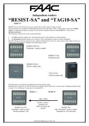
“COBRA <strong>600</strong>”<br />
MANAGEMENT UNIT<br />
EPROM Ver.5.7.6x<br />
<strong>Manual</strong> Rev. C of 29.06.2000<br />
\\Pc5\docword\Doc00\15manual\FaacControl\<strong>Cobra</strong><strong>600</strong>\<strong>Manual</strong>e <strong>Cobra</strong><strong>600</strong> - V 5-7-6x.doc<br />
<strong>FAAC</strong> s.p.a. Pagina 1
CONTENTS<br />
1. DESCRIPTION OF “COBRA <strong>600</strong>” CONTROL UNIT .............................................................. 4<br />
1.1 FEATURES ................................................................................................................................... 4<br />
1.2 “ON-LINE” AND “STAND-ALONE” MODES................................................................................ 5<br />
1.2.1 CHARACTERISTICS IN "STAND-ALONE" MODE. ..................................................................... 5<br />
1.2.2 OPERATIONAL FUNCTIONS IN "STAND-ALONE" MODE. ......................................................... 6<br />
1.2.3 LIMITATIONS AND NON-OPERATIONAL FUNCTIONS IN "STAND-ALONE" MODE. ................... 6<br />
1.3 OPERATING MODES.................................................................................................................... 6<br />
1.3.1 “ACCESS CONTROL” MODE ................................................................................................... 7<br />
1.3.2 “TIME & ATTENDANCE” MODE............................................................................................. 7<br />
1.3.3 “EXCESS” MODE.................................................................................................................... 7<br />
1.4 DISABLING THE “SITE CODE” TEST .......................................................................................... 7<br />
2. CONNECTIONS LAY-OUT ......................................................................................................... 8<br />
3. CARD READING ......................................................................................................................... 11<br />
3.1 MAGNETIC-STRIPE................................................................................................................... 12<br />
3.2 WIEGAND .................................................................................................................................. 12<br />
3.3 “T” AND “N” PREFIX................................................................................................................ 13<br />
3.4 CODE CONTROL SETTINGS....................................................................................................... 15<br />
3.5 LRC CONTROL......................................................................................................................... 16<br />
3.6 IGNORE CARDS ......................................................................................................................... 16<br />
3.7 DISABLE TIME BAND TEST ...................................................................................................... 17<br />
3.8 DISPLAY AND COMMUNICATION SETTINGS ............................................................................ 17<br />
3.8.1 REASONS ............................................................................................................................. 18<br />
3.8.2 ENTRANCE/EXIT/NEUTRAL ................................................................................................. 18<br />
3.8.3 WORD ON DISPLAY.............................................................................................................. 18<br />
3.9 REPLACEMENT PIN FUNCTION ................................................................................................ 18<br />
3.10 PIN FUNCTION......................................................................................................................... 19<br />
3.10.1 CARDS NOT REQUIRING A PIN ........................................................................................... 19<br />
3.10.2 SUSPENSION OF PIN ON A TIME-BAND ............................................................................... 19<br />
4. MISCELLANEOUS FUNCTIONS ............................................................................................. 19<br />
4.1 TENTHS / SECONDS................................................................................................................... 19<br />
4.2 PROGRAMMABLE INPUTS LOGIC............................................................................................. 21<br />
4.3 TRANSIT MEMORY SHUT-DOWN .............................................................................................. 21<br />
4.4 BAUD-RATE CHANGE ............................................................................................................... 21<br />
5. MISCELLANEOUS MANAGEMENT ...................................................................................... 21<br />
5.1 MANAGEMENT OF VEHICLE GATEWAYS WITH MAGNETIC LOOPS....................................... 21<br />
5.1.1 INTRODUCTION .................................................................................................................... 21<br />
\\Pc5\docword\Doc00\15manual\FaacControl\<strong>Cobra</strong><strong>600</strong>\<strong>Manual</strong>e <strong>Cobra</strong><strong>600</strong> - V 5-7-6x.doc<br />
<strong>FAAC</strong> s.p.a. Pagina 2
5.1.2 PROGRAMMING.................................................................................................................... 22<br />
5.2 DOUBLE DOOR MANAGEMENT (READER A ON ONE GATEWAY, B ON THE OTHER) ............. 22<br />
5.2.1 INTRODUCTION .................................................................................................................... 22<br />
5.2.2 HOW TO PROGRAM .............................................................................................................. 23<br />
5.2.2.1 PROGRAMMING FROM "WINCONTROL" .................................................................... 23<br />
5.2.2.2 PROGRAMMING FROM THE KEYBOARD ......................................................................... 24<br />
5.2.3 MISCELLANEOUS NOTES...................................................................................................... 24<br />
5.2.4 “DOOR MANAGEMENT” FOR TWO SEPARATE GATEWAYS.................................................... 24<br />
5.3 DISABLING READER A AND READER B.................................................................................... 25<br />
5.4 INTERFACING WITH ALARM CONTROL UNITS....................................................................... 25<br />
5.4.1 INPUT MANAGEMENT FROM ALARM CONTROL UNIT MODE 0 .............................................. 25<br />
5.4.2 INPUT MANAGEMENT FROM ALARM CONTROL UNIT MODE 1 ............................................. 26<br />
5.5 “MONODIRECTIONAL” OR “BIDIRECTIONAL” MODE............................................................ 26<br />
5.6 “NORMAL” MODE OR “DOOR MANAGEMENT”...................................................................... 27<br />
5.7 ANTI-COERCION IN "STAND-ALONE" MODE.......................................................................... 27<br />
5.8 ACTIVATING OPERATIONS ON TIME-BAND ............................................................................ 28<br />
6. SETTINGS OF COBRA <strong>600</strong> CARD ........................................................................................... 28<br />
6.1 PROGRAMMING FROM THE KEYBOARD.................................................................................. 28<br />
APPENDIX .......................................................................................................................................... 37<br />
6.2 DISPLAY OF CURRENT VERSION .............................................................................................. 37<br />
6.2.1 DISPLAY IDENTIFYING A OR B ........................................................................................... 37<br />
6.2.2 CHANGING THE EPROM ..................................................................................................... 37<br />
6.3 PROGRAMMING SUMMARY TABLE.......................................................................................... 38<br />
SYSTEM ARCHITECTURE...................................................................................................................... 39<br />
6.5 WIRING ................................................................................................................................... 41<br />
6.5.1 CONVERTER FOR INTERFACING RS 232/485 1 LINE............................................... 42<br />
6.5.2 CONVERTER FOR INTERFACING RS 232/485 4 LINES ............................................ 43<br />
6.5.3 COBRA <strong>600</strong> ........................................................................................................................ 44<br />
6.5.4 GATEWAY “B” BARRIER...................................................................................................... 45<br />
6.5.5 DETECTOR FG-2............................................................................................................... 46<br />
6.5.6 MAG READER................................................................................................................... 47<br />
6.5.7 TAG-3 READER ................................................................................................................ 48<br />
6.5.8 TAG-5 READER ................................................................................................................ 49<br />
6.5.9 TAG-10 READER ..............................................................................................................50<br />
6.5.10 DIGIMAG ......................................................................................................................... 51<br />
6.5.11 DIGITAG .......................................................................................................................... 52<br />
6.5.12 RADIO-CONTROL 433SLP ............................................................................................ 53<br />
6.5.13 MIXER CARD .................................................................................................................. 54<br />
6.5.14 AT-8 .................................................................................................................................. 55<br />
\\Pc5\docword\Doc00\15manual\FaacControl\<strong>Cobra</strong><strong>600</strong>\<strong>Manual</strong>e <strong>Cobra</strong><strong>600</strong> - V 5-7-6x.doc<br />
<strong>FAAC</strong> s.p.a. Pagina 3
1. Description of “COBRA <strong>600</strong>” control unit<br />
The "COBRA <strong>600</strong>" control unit is a peripheral device of the “WinNet” network able to communicate with the<br />
Controller.<br />
The Controller is a PC on which the WINCONTROL program, with Win95, Win98, WinNT or Win2000, is installed<br />
and executed.<br />
One or two card readers of different technology can be connected to the control unit – i.e. magnetic, proximity etc, with<br />
or without keyboard and display.<br />
Every control unit has 6 inputs with various use, i.e. door status, sensors, photocells, alarm contacts, etc, and 4 outputs<br />
(2 with relay and 2 open collector) utilised for electric locks, activators, lighting, “traffic lights”, etc.<br />
An RS 485 serial port and an RS 232 port are provided for connection to the “WinNet” network.<br />
The information contained in this manual refers to the standard EPROM version for polling on the “WinNet” network.<br />
The standard "COBRA <strong>600</strong>" control unit has no additional (or auxiliary) serial ports. To make use of an additional<br />
auxiliary RS 232 serial port, the "COBRA <strong>600</strong>/S" control unit must be ordered – this port requires some EPROM<br />
variations (see relevant paragraph), which, therefore, require the "COBRA <strong>600</strong>/S” version.<br />
The additional auxiliary serial port is needed for interfacing with a serial printer, optical reader, etc, according to case.<br />
The "COBRA <strong>600</strong>" control unit is supplied with a “Clock Module” with a lithium buffer or floating battery, enabling the<br />
control unit to add local date/time to card reading data - this function is particularly useful for Time & Attendance and<br />
for activating relays on the time-band without using the Controller.<br />
As concerns the Time & Attendance facility, the user should directly see the date/time of the “stamp”, and therefore, we<br />
advise you to use readers complete with keyboard /display.<br />
The system normally operates with the "COBRA <strong>600</strong>" control units on-line - in this case, one refers to “On-line” mode.<br />
This is the only mode ensuring all the functions possible with the program installed on the PC.<br />
If communication with the Controller is interrupted, the "COBRA <strong>600</strong>" control unit switches to “Stand-Alone” mode.<br />
Only some of the functions are possible in this mode, and, therefore, some limitations are inevitable.<br />
on system level<br />
on "COBRA <strong>600</strong>" level<br />
A paragraph will describe these limitations.<br />
1.1 Features<br />
Local memory for card archive, time-bands, public holidays.<br />
Archives sent from PC<br />
Lithium battery for maintaining data-memory and clock/dater ever in the event of a power cut..<br />
Functional settings saved on a non-volatile memory (EEPROM).<br />
Programming by PC of functional settings.<br />
Local buffer memory containing <strong>600</strong> user codes.<br />
Local buffer memory containing 1750 transactions.<br />
Facility for activating reading shut-down if the transits memory is full.<br />
32 Kbyte RAM with lithium battery to maintain data even in the event of power failure.<br />
RAM used partly for the transactions buffer and the remainder for archives (cards, time-bands, public holidays).<br />
Complete management of gateway or door.<br />
Incomplete management of 2 separate gateways (reader A on one door and reader B on the other)<br />
Maximum distance between a "COBRA <strong>600</strong>" and a reader without keyboard / display : 100 mt.<br />
Maximum distance between a "COBRA <strong>600</strong>" and a reader with keyboard / display : 40 mt.<br />
Power supply voltage; 230 Vac (+6% -10%) 50 (60) Hz<br />
Maximum absorption: 900mA (varies according to number of connected readers).<br />
Important note : only the main settings are possible from the PC in a way that is clear to the user.<br />
However, other settings are possible, by programming appropriate values in certain areas of the memory.<br />
This is possible from both WINCONTROL (“EEPROM Reading/writing”) and from the programming keyboard on the<br />
"COBRA <strong>600</strong>".<br />
As an example of programming, you will find the following symbols in the manual: 486 (18)dec<br />
This means: send (or write) decimal number 18 to location #486.<br />
The described programming will be shown during the explanation and at the end of each paragraph.<br />
\\Pc5\docword\Doc00\15manual\FaacControl\<strong>Cobra</strong><strong>600</strong>\<strong>Manual</strong>e <strong>Cobra</strong><strong>600</strong> - V 5-7-6x.doc<br />
<strong>FAAC</strong> s.p.a. Pagina 4
1.2 “On-line” and “Stand-Alone” modes.<br />
The "COBRA <strong>600</strong>" control unit is able to operate both by communication with the PC (“On-line” mode) and locally<br />
(“Stand-Alone” mode), if communication with the PC is interrupted.<br />
In other words, "COBRA <strong>600</strong>" has decision making ability and this makes it possible not to interrupt the Access Control<br />
service and, if necessary, the Time & Attendance service.<br />
Switching from “On-line” and “Stand-alone” modes (and vice versa) is automatic depending on whether communication<br />
is activated with the Controller (polling) or not.<br />
In “On-line” mode, every "COBRA <strong>600</strong>" panel continuously dialogues with the PC (polling), transmitting every<br />
detected event in real-time. All decisions regarding a transit are delegated to the Controller (on which<br />
“WINCONTROL” software is applied) which records it in the “Historical Archive”. Before being enabled for transit,<br />
every card is subjected to all the controls specified in the “WINCONTROL” software for “Access Control” (see relevant<br />
manual).<br />
In “Stand Alone” mode, all decisions regarding transit by card, is made by the panel: all transits related data are<br />
recorded on the terminal’s non-volatile memory and are automatically downloaded toward the Controller, as soon as<br />
communication is restored.<br />
Enabled opening by the panel is based on personal-data archives also stored in the panel’s non-volatile memory.<br />
The terminal’s memory capacity does not allow complete management in “Stand-Alone” mode, as if the panel were<br />
“On-line” (communicating) with the Controller, but is sufficient to deal with a temporarily interrupted communication.<br />
The panel can be programmed so that it is forced to operate always in "On-line" mode or always in "Stand-alone" mode<br />
(this will be described in detail later in the manual).<br />
Forcing a "COBRA <strong>600</strong>" control unit to always operate "On-line", overrides any forcing to operate in "Stand-alone"<br />
mode.<br />
This facility is set either by Programming on the "COBRA <strong>600</strong>" keyboard or with the following commands:<br />
Always "On-line" 432 (00)dec (432 (255)dec to disable)<br />
Always "Stand-alone" 428 (00)dec (428 (255)dec to disable)<br />
The always "On-line" mode is used for this reason:<br />
to force the system to operate only if the PC is on-line in special applications. If the system is being polled by the<br />
PC, everything functions as described – if it is not being polled, the card, alarms etc. are ignored as local management is<br />
disabled.<br />
The Always “Stand-alone” mode is in operation, even if communication with the Controller (active polling) is active.<br />
In this case, if a card is read, the validity decision is made by "COBRA <strong>600</strong>" – if the card is valid, the transit data-item is<br />
sent to the internal buffer. If "COBRA <strong>600</strong>" is communicating with the Controller, the information is immediately<br />
transferred to the PC, or it will be as soon as communication is restored. Note the significant difference between the<br />
modes:<br />
if "On-line", the decision is made by the PC which immediately re-sends the result to "COBRA <strong>600</strong>"<br />
if "Stand-alone", the decision is made by "COBRA <strong>600</strong>" and is then communicated to the PC which does no more<br />
than archive it.<br />
We shall now describe the functions of a panel in "Stand-alone" mode and the limitations compared to the "On-line"<br />
mode.<br />
1.2.1 Characteristics in "Stand-alone" mode.<br />
The following paragraph explains the memory limits of a "COBRA <strong>600</strong>" panel in "Stand-alone" mode.<br />
Historical archive :<br />
1750 transits (that used to be 1770 up to 5.7.1 version) are stored in a circular buffer – if it is full, new data are<br />
overwritten over the oldest.<br />
Facility for preventing readings if the buffer is full – to re-enable reading, data must be downloaded to the PC.<br />
This facility is set either by Programming on the "COBRA <strong>600</strong>" keyboard or with the following command:<br />
Historical archive shut-down 292 (00)dec (292 (255)dec to disable)<br />
Data of valid transits only are normally archived to allow maximum space for this function (therefore alarms, restoring<br />
operations, invalid cards, etc are not archived).<br />
Alarms must also be stored in some applications. By programming one can do the following:<br />
archive alarms + restoring operations + valid transits (414 (00)dec)<br />
archive alarms + valid transits (414 (00)dec + 413 (00)dec)<br />
Other archives:<br />
\\Pc5\docword\Doc00\15manual\FaacControl\<strong>Cobra</strong><strong>600</strong>\<strong>Manual</strong>e <strong>Cobra</strong><strong>600</strong> - V 5-7-6x.doc<br />
<strong>FAAC</strong> s.p.a. Pagina 5
Storing data of a maximum of <strong>600</strong> cards (see note further below) (was 598 up to 5.7.1. version)<br />
Storing data of a maximum of 255 time bands (N.B.: numbered from 1 to 255)<br />
Storing data of a maximum of 32 days defined as “Holidays”.<br />
N.B.: the limits of some EPROM options and of customised EPROMs can be expanded in order to accommodate more<br />
cards in the memory and, therefore - less space is reserved for transactions and vice versa.<br />
“WINCONTROL” is not designed to send the “Accesses Level” archive to the "COBRA <strong>600</strong>" control unit and neither<br />
does it send – card by card - information on the associated “Accesses Level”.<br />
Instead, “WINCONTROL” sends to a certain control unit only those cards which are potentially valid there.<br />
This is typically effected according to the primary “Accesses Level” only. As from the 2.33.34 version of the<br />
“WINCONTROL” program, the other “Accesses Levels” associated with a card are also analysed - for further<br />
information, see the current program manual. However, the “Accesses Level” associated with the reason is not used.<br />
The Card archive is sent in increasing numerical order according to the “Card Code”: first the lowest numbers and then<br />
the highest. Therefore, only some cards (or even no cards) may be sent to a given "COBRA <strong>600</strong>".<br />
The program sends all relevant cards to the control unit - it may send more cards than can be contained in the specified<br />
capacity of the installed EPROM (<strong>600</strong> for the standard version).<br />
In this case, the "COBRA <strong>600</strong>" control unit stores the first <strong>600</strong> received (if it is the standard version) and ignores the<br />
rest.<br />
1.2.2 Operational functions in "Stand-alone" mode.<br />
The following function remain in operation in the "Stand-alone" mode (see the “WINCONTROL” manual for possible<br />
explanations of the functions listed below):<br />
check of card validity per time band and accesses level (typically primary level only – additional levels are also<br />
considered as from the 2.33.34 version of "WINCONTROL")<br />
full use of the “character sequence” association<br />
validity of only the first “Site Code” (the one on the left) of the three on the mask in the panels archive<br />
activation of the four outputs for valid cards (the valid card action message is not executed)<br />
different activating operations between reader A and reader B (this is a local decision of "COBRA <strong>600</strong>" in "Online"<br />
mode too)<br />
activation of one output for non-valid cards (the non-valid card action message is not executed)<br />
an Activation Card executes only the activation operations specified for that panel and not those for other panels<br />
(which, furthermore, are not on-line if "Stand-alone")<br />
PIN function (only in the following order: type code + presenting card and not vice versa)<br />
PIN suspended for Time Band + Exit always valid<br />
PINSOST function, i.e. PIN replacing a card<br />
a reason explanation can be typed before presenting the card<br />
Activation of exits according to time band (OUT1 – OUT4 are activated if current time is within the specified time<br />
band). N.B.: activation according to time band is a decision made by the panel even in "On-line" mode<br />
archival of card data, date/time, reason and relevant reading head (A or B)<br />
activating operations associated with entrances providing they concern the same panel<br />
1.2.3 Limitations and non-operational functions in "Stand-alone" mode.<br />
In "Stand-alone" mode, "COBRA <strong>600</strong>" operates at a lower performance level – details below:<br />
limit: recognition of a maximum of <strong>600</strong> cards (if standard version)<br />
limit: only 1750 transits can be stored in the memory<br />
card validity decisions made locally according to the latest data download operation<br />
present/absent count in real-time on "WINCONTROL" (however, the count is updated automatically while the<br />
historical data is being downloaded as soon as the panel resumes "On-line" status)<br />
“antipass-back” function<br />
action messages of any kind as not downloaded into the "COBRA <strong>600</strong>" memory<br />
subscriber cards<br />
enabling / disabling cards for a certain period<br />
validity extended for subscriber cards<br />
antipass-back disabled for certain cards<br />
simplified access (rudimentary type)<br />
1.3 Operating modes<br />
In "Stand-alone" status the "COBRA <strong>600</strong>" control unit can operate in three modes:<br />
1. standard “Access control” mode (as described up to now)<br />
2. “ Time & Attendance ” mode<br />
3. “Excess” mode<br />
\\Pc5\docword\Doc00\15manual\FaacControl\<strong>Cobra</strong><strong>600</strong>\<strong>Manual</strong>e <strong>Cobra</strong><strong>600</strong> - V 5-7-6x.doc<br />
<strong>FAAC</strong> s.p.a. Pagina 6
The setting is input by keyboard Programming on "COBRA <strong>600</strong>".<br />
1.3.1 “Access Control” mode<br />
This is the standard operating mode. The card validity check is performed according to COBRA <strong>600</strong> ‘s internal archives.<br />
The last archives to be downloaded from the Controller apply.<br />
maximum number of cards in the memory is <strong>600</strong><br />
maximum number of transits in the memory is 1750 in the standard versions<br />
“Access control” mode 427 (255)dec (default)<br />
In minimum security cases, the Site Code test can be disabled (see paragraph).<br />
This facility is set either by Programming on the "COBRA <strong>600</strong>" keyboard or with the following command:<br />
Disable Install. Code test 289 (00)dec (289 (255)dec to restore)<br />
1.3.2 “Time & Attendance” mode<br />
If this mode is activated, and the "COBRA <strong>600</strong>" control unit is in "Stand-alone" status, it executes some much more<br />
rudimentary tests when each card is read, to the extent that the Card archive need not be downloaded for it to function.<br />
N.B.: - the “T” prefix must be active<br />
- the always "Stand-alone" function must be activated<br />
Under these conditions, a card is considered valid if:<br />
the card number is in the range from 1 to 65535<br />
the read site code is in the range 1 to 65535 and coincides with that of "COBRA <strong>600</strong>"<br />
In practice, the card is checked to see if it belongs to the system and has a number within the specified range.<br />
No tests are run on time bands or for other purposes.<br />
“ Time & Attendance ” mode 427 (00)dec (427 (255)dec to restore the “Access Control” mode)<br />
In minimum security cases, the Site Code test can be disabled.<br />
This facility is set either by Programming on the "COBRA <strong>600</strong>" keyboard or with the following command:<br />
Disable Install. Code test 289 (00)dec (289 (255)dec to restore)<br />
Although downloading the Card archive is not necessary in this mode, the number of transits that can be stored in the<br />
memory is the same.<br />
If communication with "WINCONTROL" is re-established, transit data are immediately downloaded from "COBRA<br />
<strong>600</strong>".<br />
Important : the advantage of this mode is that the limit of <strong>600</strong> cards becomes 65535.<br />
1.3.3 “Excess” mode<br />
If this mode is activated, and "COBRA <strong>600</strong>" if in "Stand-alone" status, it behaves in a hybrid way, according to the<br />
number of downloaded cards.<br />
if below capacity (<strong>600</strong> for basic EPROM) “ Time & Attendance ” mode<br />
If acceptable on a system level, this makes it possible to have several "COBRA <strong>600</strong>" operating normally if On-line, but<br />
continuing to recognise all cards (subject to the limits we mentioned) if they change to off-line.<br />
N.B.: - the “T” prefix must be active<br />
- the always "Stand-alone" function must not be activated<br />
“Excess” mode 427 (01)dec (427 (255)dec to restore the “Access Control” mode”)<br />
1.4 Disabling the “Site code” test<br />
Up to the 5.7.5b version, one could disable the “Site Code” test only if in “Time & Attendance” mode (see relevant<br />
paragraph ).<br />
As from the 5.7.5c version, one can disable this test also in the "Access Control" mode (i.e. the standard one) and in<br />
“Excess” mode.<br />
This can be done only if in “T” Prefix. In fact, there is no sense in talking about “Site Code” with the “N” Prefix<br />
(“character sequence association”).<br />
This function should operate in the following :<br />
Stand-alone<br />
On-line<br />
Magnetic-Stripe input<br />
\\Pc5\docword\Doc00\15manual\FaacControl\<strong>Cobra</strong><strong>600</strong>\<strong>Manual</strong>e <strong>Cobra</strong><strong>600</strong> - V 5-7-6x.doc<br />
<strong>FAAC</strong> s.p.a. Pagina 7
Wiegand input<br />
If in "Stand-alone" mode, any “Site Code” read on the card is acceptable for card validity. When transit data are<br />
communicated to the Controller, the “Site Code” programmed on "COBRA <strong>600</strong>" will be used.<br />
If in "On-line" mode, transit data will be communicated to the Controller, using the “Site Code” programmed on<br />
"COBRA <strong>600</strong>" and not data read on the card.<br />
To disable the “Site Code” test:<br />
This facility is set either by Programming on the "COBRA <strong>600</strong>" keyboard or with the following command:<br />
Disable Install. Code test 289 (00)dec (289 (255)dec to restore)<br />
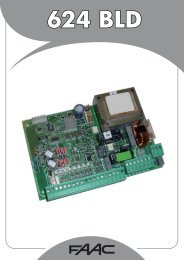
2. Connections lay-out<br />
DB 25 DB 9<br />
7 5 GND<br />
2 3 Tx<br />
3 2 Rx<br />
connections to<br />
RS 232 PC<br />
Minimum cable diameter:<br />
+12V and GND 0,5 mm 2<br />
remaining 7 poles 0,22 mm 2<br />
READER A<br />
Connect the reader<br />
with 9-pole cable + shield<br />
Connect the shield<br />
to the GDN terminal<br />
from both sides<br />
READER B<br />
input/output<br />
RS485<br />
input/output<br />
MISO<br />
MOSI<br />
SCK<br />
SS-N<br />
+12V<br />
GND<br />
D1-DATO<br />
D0-CLK<br />
BUZ<br />
MISO<br />
MOSI<br />
SCK<br />
SS-N<br />
+12V<br />
GND<br />
D1-DATO<br />
D0-CLK<br />
BUZ<br />
+485<br />
-485<br />
SHIELD<br />
+485<br />
-485<br />
SHIELD<br />
1<br />
2<br />
3<br />
4<br />
5<br />
6<br />
7<br />
8<br />
9<br />
1<br />
2<br />
3<br />
4<br />
5<br />
6<br />
7<br />
8<br />
9<br />
1<br />
2<br />
3<br />
1<br />
2<br />
3<br />
COM2<br />
M1<br />
M2<br />
M3<br />
M4<br />
M12 1 2 3 4 5 1 2 3 4 5 M13<br />
Tx RTS GND Tx RTS GND<br />
Rx GND Rx CTS<br />
1 2 3<br />
J11<br />
JP1 Removable card<br />
1<br />
J5<br />
J6<br />
EPROM<br />
with Progr.<br />
Galvanically<br />
separated area<br />
for RS485<br />
Relay 2<br />
Relay 1<br />
POWER SUPPLY<br />
11<br />
Out3 LED<br />
Relay 2 LED<br />
Power LED<br />
M7<br />
Relay 1 LED<br />
M5 1 2<br />
COM1 (SA64/S only<br />
\\Pc5\docword\Doc00\15manual\FaacControl\<strong>Cobra</strong><strong>600</strong>\<strong>Manual</strong>e <strong>Cobra</strong><strong>600</strong> - V 5-7-6x.doc<br />
<strong>FAAC</strong> s.p.a. Pagina 8<br />
M11<br />
2<br />
1<br />
8<br />
7<br />
6<br />
5<br />
M10 4<br />
3<br />
2<br />
1<br />
Auxiliary<br />
connector J3<br />
1 Out4<br />
M9<br />
LED<br />
M8<br />
M6<br />
3<br />
2<br />
1<br />
3<br />
2<br />
1<br />
3<br />
2<br />
1<br />
3<br />
2<br />
1<br />
GND<br />
IN7<br />
GND<br />
GND<br />
IN6<br />
IN5<br />
IN4<br />
IN3<br />
IN2<br />
IN1<br />
+12V<br />
OUT4<br />
OUT3<br />
NO<br />
COM<br />
NC<br />
NO<br />
COM<br />
NC<br />
NO<br />
COM<br />
NC<br />
Rx<br />
Tx<br />
CTS<br />
RTS<br />
GND<br />
OUT-OC<br />
RELAY 2<br />
1/B<br />
1/A<br />
N.B.: 1/A contact not free<br />
COM is on<br />
GND<br />
GND<br />
POWER SUPPLY 12:14 Vdc<br />
Optional<br />
REMOTE DEV ICE<br />
(printers, barcode readers, etc.)<br />
TAMPER<br />
RELAY 1<br />
INPUT
The "COBRA <strong>600</strong>" control unit consists of 2 cards connected one above the other by a 60-pole connector.<br />
The basic card is used for fastening, to support the terminals, and houses the “RS 485” section, the power supply to the<br />
digital section, the outputs (with or without relays), the input stages, and the “RS 2322” stages for variations to the basic<br />
version for which they are specified.<br />
The small card is fitted on SMD and is connected to the previous one by a 60-pole connector (2 rows of 30); it houses<br />
the CPU, the EEPROM non-volatile memory, the buffered memory and the Clock Module.<br />
There are several functional logic blocks on "COBRA <strong>600</strong>". They typically communicate with the outside world via<br />
terminals. The blocks are:<br />
power supply unit<br />
serial port for polling in RS485 (WinNet)<br />
serial port for polling in RS232 (COM2)<br />
auxiliary RS232 (COM1) serial port on COBRA <strong>600</strong>/S only<br />
Connection for reader A<br />
Connection for reader B<br />
physical inputs<br />
outputs<br />
Power supply<br />
The terminal board associated with M5 is a standard 12 Vdc (11.3-13.8 Vdc) power supply.<br />
The "COBRA <strong>600</strong>" control unit is equipped with the “ALI SA device, a power supply unit at 220/240 Vac with 12Vdc<br />
output.<br />
Serial port for polling in RS485 (WinNet)<br />
The associated terminal boards are M3 and M4.<br />
This port can be used only if the RS232 (COM2) port is not being used either.<br />
Connect as described in the figure of the control unit.<br />
The serial port is opto-isolated. Two 3-pole terminal boards are provided – they are identical to each other because the<br />
corresponding Pins are connected in parallel: use one terminal board for the incoming line and the other for the<br />
outgoing line.<br />
Meaning of Pins:<br />
Pin1: +485<br />
Pin2: -485<br />
Pin3: Cable shield<br />
N.B.: the shield is isolated and is not connected to the card’s GND: it serves only for anchoring the braids of the dataline<br />
cables.<br />
Serial port for polling in RS232 (COM2)<br />
The associated terminal board is M12.<br />
This port can be used only if the RS485 port is not being used either.<br />
Connect as described in the figure of the control unit.<br />
By using this serial port, a direct point-to-point connection on RS232 between one of the Conroller PC’s serial ports and<br />
just one "COBRA <strong>600</strong>" control unit is possible (max. distance 15 m).<br />
Auxiliary RS232 (COM1) serial port.<br />
The associated terminal board is M13.<br />
This port is available only on the "COBRA <strong>600</strong>/S" control unit.<br />
This terminal board can be installed on the panel to enable communication with peripheral devices such as optical<br />
readers, printers, etc.<br />
The "COBRA <strong>600</strong>/S" control units have more components installed on their card than the standard "COBRA <strong>600</strong>" .<br />
Connection for reader A<br />
The associated terminal board is M1.<br />
"COBRA <strong>600</strong>" can be programmed to read Wiegand or Magnetic-Stripe codes.<br />
N.B.: if Magnetic Stripe (or Wiegand) is set, it applies to both reader A and B.<br />
Note that Wiegand is the standard output for Cotag readers, whereas Magnetic-Stripe is the standard for Credit Card<br />
type coded cards (ABA).<br />
The keyboard / display is built into certain types of reader (see catalogue).<br />
The maximum distance for this type of connection is 40 metres if the keyboard/display is supplied, and about 100 metres<br />
for card readers only.<br />
\\Pc5\docword\Doc00\15manual\FaacControl\<strong>Cobra</strong><strong>600</strong>\<strong>Manual</strong>e <strong>Cobra</strong><strong>600</strong> - V 5-7-6x.doc<br />
<strong>FAAC</strong> s.p.a. Pagina 9
Connection for reader B<br />
The associated terminal board is M2.<br />
"COBRA <strong>600</strong>" can be programmed to read Wiegand or Magnetic-Stripe codes.<br />
N.B.: if Magnetic Stripe (or Wiegand) is set, it applies to both reader A and B.<br />
Note that Wiegand is the standard output for Cotag readers, whereas Magnetic-Stripe is the standard for Credit Card<br />
type coded cards (ABA).<br />
The keyboard / display is built into certain types of reader (see catalogue).<br />
The maximum distance for this type of connection is 40 metres if the keyboard/display is supplied, and about 100 metres<br />
for card readers only.<br />
Inputs:<br />
The associated terminal boards are M10 and M11.<br />
M10 is an 8-pole terminal: it is used for inputs from 1 to 6.<br />
M11 is an 2-pole terminal: it is used for input 7, usually dedicated to the Tamper.<br />
Total inputs are 7. They should be activated by connecting them to GDN and using a free contact.<br />
If necessary, they may be connected directly to OUT3 and OUT45 open collector.<br />
The function logic can be programmed, i.e. if the inputs have to be activated by “normally open” or “normally closed”<br />
contacts. The following table describes the pre-defined settings and the meanings of Pins.<br />
TERMINAL INPUT STATUS WITH PRE-DEFINED LOGIC AND<br />
TERMINAL LEFT FREE<br />
PRE-DEF.<br />
LOGIC<br />
M10-Pin1 IN1 Restore Normally open<br />
M10-Pin2 IN2 Restore Normally open<br />
M10-Pin3 IN3 Restore Normally open<br />
M10-Pin4 IN4 Restore Normally open<br />
M10-Pin5 IN5 Restore Normally open<br />
M10-Pin6 IN6 Restore Normally open<br />
M10-Pin7 GND<br />
M10-Pin8 GND<br />
M11-Pin1 IN7 Alarm Normally closed<br />
M11-Pin2 GND<br />
“Normally open” logic means that:<br />
there is no tick-mark on WINCONTROL’s “On-line panel initialisation” screen mask<br />
the input left disconnected is in Restore state.<br />
the input connected to GND is in Alarm status.<br />
“Normally closed” logic means that:<br />
there is a tick-mark on WINCONTROL’s “On-line panel initialisation” screen mask<br />
the input connected to GND is in Restore status.<br />
the input left disconnected is in Alarm state.<br />
All M10 inputs is in restore status if left disconnected and with a pre-defined logic - to put it in alarm status, it must be<br />
connected to GND.<br />
The tamper input is normally in alarm status: to put it in restore status, it must be connected to GND.<br />
Some inputs can have alternative functions according to setting or EEPROM version.<br />
Outputs<br />
The associated terminal boards are M6, M7, M8 and M9.<br />
Four outputs are available. These outputs have no pre-defined function and, therefore, can be utilised at the user’s<br />
discretion. A valid card can activate all 4 outputs or part of them at a time settable for each. Everyone of the 4 control<br />
outputs can be activated on a time band basis too. If a valid card activates for a certain period an output that is already<br />
enabled as it is within a time-band, when the relevant time elapses, the output remains activated because the timed<br />
activation command is ignored and the time-band is given priority.<br />
OUT1 activates RELAY1/A and RELAY1/B; 2 exchanges are available on a terminal, one of which is not<br />
free (see below)<br />
OUT2 activates RELAY2; 1 free exchange available on a terminal<br />
\\Pc5\docword\Doc00\15manual\FaacControl\<strong>Cobra</strong><strong>600</strong>\<strong>Manual</strong>e <strong>Cobra</strong><strong>600</strong> - V 5-7-6x.doc<br />
<strong>FAAC</strong> s.p.a. Pagina 10
OUT3 is open collector type; 100 mA max; no protective diode is supplied at counter-phase<br />
OUT4 is open collector type; 100 mA max; no protective diode is supplied at counter-phase<br />
N.B.: If connecting one ore more outputs of the "COBRA <strong>600</strong>" panel using direct current electro-actuators, make sure<br />
that these devices are equipped with adequate protective diodes in parallel, and have a different power supply from that<br />
of the panel itself.<br />
Noise induced by external actuators could reset COBRA <strong>600</strong>’s CPU at every activating/de-activating operation..<br />
Remember that different activating operations can be defined for readers A and B: a paragraph will describe how to<br />
proceed.<br />
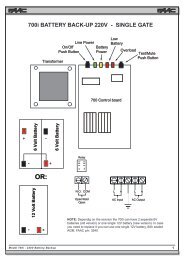
N.B.: OUT1 has a double exchange: section A of the relay does not have free exchanges because its COM is already<br />
connected to the card’s GND - this connection can be excluded by interrupting a card bed on the exposed side of the<br />
card to the left of the terminal in question, as shown in the figure.<br />
It can always be restored later with a drop of solder.<br />
SA64 card,<br />
top side<br />
Relay 1<br />
Pow er LED<br />
Relay 1 LED<br />
1 2<br />
Auxiliary connector: description of Pins<br />
J3<br />
level CMOS (0- 5V) OUT5-AUX 1 2 +12V<br />
level CMOS (0- 5V) OUT4-AUX 3 4 IN4-AUX<br />
level CMOS (0- 5V) OUT3-AUX 5 6 IN3-AUX<br />
level CMOS (0- 5V) OUT2-AUX 7 8 IN2-AUX<br />
Open-Collector OUT1-AUX (*) 9 10 IN1-AUX<br />
GND 11 12 GND<br />
(*): OUT1-AUX is an Open-Collector type output.<br />
N.B.: OUT1-AUX is active if the Panel is in "Stand-alone" mode (basic options only).<br />
Outputs from OUT2-AUX to OUT5-AUX are at level CMOS (0- 5V).<br />
Inputs from IN1-AUX to IN4-AUX should be activated with free contacts toward GND.<br />
3<br />
2<br />
1<br />
3<br />
2<br />
1<br />
NC<br />
COM<br />
NC<br />
NC<br />
COM<br />
NC<br />
OUT 1/B<br />
OUT 1/A<br />
Not a<br />
free contact<br />
Relay 1<br />
Interrupt connection<br />
to make the contact free<br />
3. Card reading<br />
One of "COBRA <strong>600</strong>" control unit’s most important functions is card reading.<br />
The control unit has no built-in readers but has inputs for interfacing with a maximum of 2 readers: reader A and reader<br />
B:<br />
Each input consists of 2 Pins named D0-CLOCK and D1-DATO.<br />
\\Pc5\docword\Doc00\15manual\FaacControl\<strong>Cobra</strong><strong>600</strong>\<strong>Manual</strong>e <strong>Cobra</strong><strong>600</strong> - V 5-7-6x.doc<br />
<strong>FAAC</strong> s.p.a. Pagina 11
The program is able to decode two types of readers:<br />
readers with Magnetic-Stripe output<br />
readers with Wiegand output<br />
The "COBRA <strong>600</strong>" control unit is delivered (unless otherwise agreed) preset for interfacing Magnetic-Stripe readers.<br />
The setting can be modified from both the Controller and the keyboard.<br />
The "COBRA <strong>600</strong>" control unit waits for a code from one of the two readers and dedicates itself to receiving the first to<br />
be activated.<br />
This means that, if the second reader is activated while the first is receiving codes, the reading from the second reader<br />
may be lost.<br />
3.1 Magnetic-Stripe<br />
The most common readers with a Magnetic-Stripe output are:<br />
both swipe and insertion type readers of magnetic cards<br />
radio-control receivers<br />
To provide full information, please note that, on request, Contag Controllers can be programmed for a Magnetic-Stripe<br />
output.<br />
However, this is used only in very special cases. A typical case is when, for economic reasons, on a single "COBRA<br />
<strong>600</strong>", a Cotag controller is connected to the A reader for vehicle Tags, and a magnetic reader to the B reader for a<br />
pedestrian gateway.<br />
As the Magnetic-Stripe (or Wiegand) setting applies to both A and B readers, the Cotag Controller is set for a Magnetic-<br />
Stripe output. Programming of Tag Cotags becomes very complicated and compatibility with the usual Tag Cotags is<br />
lost.<br />
The "COBRA <strong>600</strong>" control unit requires a Magnetic-Stripe code with a maximum of 37 characters + 3 control<br />
characters according to ABA standard<br />
A magnetic reader on ISO2 track, requiring a maximum of 37 characters + 3, must be connected.<br />
These are the control characters:<br />
Start sentinel (B)hex.........START.......located at the beginning of the useful code<br />
End sentinel (F)hex ..........STOP .........located at the end of the useful code<br />
LRC..................................LRC............located after End sentinel (Longitudinal Control of Redundancy)<br />
The string must, therefore, be of the following type: START + DATA (max. 37) + STOP + LRC<br />
If codes are in found to be correct order during decoding, reading is “normal”.<br />
If codes are in found to be reverse order (first LRC + STOP + DATA + START) during decoding, reading is<br />
“reverse”.<br />
3.2 Wiegand<br />
Readers with Wiegand output are typically:<br />
readers of active cards (Cotag controller)<br />
The "COBRA <strong>600</strong>" control unit requires a 32-bit Wiegand code which is seen as 16 + 16 bit.<br />
The first 16 bits are the Site Code in binary code. They are transformed into decimal code and take on values<br />
from 00000 to 65535<br />
The second 16 bits are the Card Code in binary code. They are transformed into decimal code and take on<br />
values from 00000 to 65535<br />
With “T” prefix. (see further below)<br />
The card is communicated to "WINCONTROL" (or internally managed if "Stand-alone") as a 10-character string, the<br />
sum of the 5 Site Codes and the 5 Card Codes.<br />
With “N” prefix. (see below)<br />
The card is communicated to "WINCONTROL" (or internally managed if "Stand-alone") as a 10-character string, the<br />
sum of the 5 Site Codes and the 5 Card Codes.<br />
So, only the prefix changes, but the rest of the code is the same.<br />
\\Pc5\docword\Doc00\15manual\FaacControl\<strong>Cobra</strong><strong>600</strong>\<strong>Manual</strong>e <strong>Cobra</strong><strong>600</strong> - V 5-7-6x.doc<br />
<strong>FAAC</strong> s.p.a. Pagina 12
3.3 “T” and “N” prefix<br />
It is very important to set the prefix because it involves the way the read codes are interpreted.<br />
This interpretation is performed by the "WINCONTROL" program, if "COBRA <strong>600</strong>" control unit is "On-line" or<br />
"COBRA <strong>600</strong>" if "Stand-alone".<br />
It is called “prefix” because the most evident effect of programming is that the first character of the string containing the<br />
data of the card sent to the Controller is a “T” or an “N” (e.g. NØØ426ØØØ32678?……..).<br />
N.B.: we inform the person monitoring communications with the “Terminal Emulation” function, that in the sent string,<br />
the “T” was replaced some time ago by a “K”, but the prefix is still referred to as a “T” prefix for the sake of continuity.<br />
With “T” prefix<br />
The "COBRA <strong>600</strong>" control unit :<br />
reads all codes on the card (e.g. ØØ426ØØØ32678)<br />
identifies the Site Code and the Card Code in precise positions (fixed for all cards).<br />
transforms the Site Code into a 5-character number with zeros at the beginning if necessary (e.g. ØØ426)<br />
transforms the Card Code into a 5-character number with zeros at the beginning if necessary (e.g. ØØ32).<br />
unites the two codes into a single 10-character string (e.g.: ØØ426ØØØ32)<br />
sends the data of the read card with the “T” prefix + 10 characters.<br />
characters that are neither Site Code nor Card Code (e.g. 678) are ignored.<br />
Procedure of instrument analysing the code ("WINCONTROL" if "On-line" or "COBRA <strong>600</strong>" if "Stand-alone") if it<br />
detects that the prefix is “T”:<br />
requires 10 numeric characters after the prefix and sees them as two groups of 5 + 5<br />
interprets the first 5 as the Site Code<br />
interprets the second 5 as the Card Code<br />
scans the internal Card archive to evaluate if a Card with that Number and that Site Code exists.<br />
if it does not exist, the card is not valid – if it does exist, the different validity tests applicable are run (time bands,<br />
etc.).<br />
To exploit this function, one must be able to program the cards:<br />
it must be possible to identify on the code one part that clearly refers to the Card Code, and another to the Site Code.<br />
This can be done with :<br />
new magnetic cards programmed by <strong>FAAC</strong><br />
active Cotag cards<br />
Prefix “T” is preferable since it is easier to manage.<br />
With “N” prefix<br />
The "COBRA <strong>600</strong>" control unit :<br />
reads all codes on the card (e.g. 4567ØØ324ØØØ256781987)<br />
if specified, the initial part and final part of the code (only in special applications) are cut in order to compose a<br />
“useful code” (ØØ324ØØØ25678)<br />
sends data with the “N” prefix + useful code (NØØ324ØØØ25678).<br />
Procedure of instrument analysing the code ("WINCONTROL" or "COBRA <strong>600</strong>" if "Stand-alone") if it detects that the<br />
prefix is “N”:<br />
scans the internal Card archive to evaluate if a Card with that code in the “Character sequence Association” field<br />
exits.<br />
if it does not exist, the card is not valid; if it does exist, the Card Code and the Site Code are extracted from it for<br />
identification, then the necessary validity tests are run (time bands, etc.)<br />
if valid, the card is archived in the historical archive with the Card Code and Site Code obtained from the Card<br />
archive, and not from the numbers read on the card (“Character sequence Association” field).<br />
It is clear that the archives must have been prepared beforehand, so that, the corresponding code was loaded in the<br />
“Character sequence Association” field card by card: the Autoread function in "WINCONTROL" is used.<br />
N.B.: it is usually advisable to have a "COBRA <strong>600</strong>" control unit close to the PC, using "WINCONTROL" for<br />
Autoreading.<br />
Most common use.<br />
The “N” prefix is used in the following cases:<br />
proximity passive cards (they have a distinct random non re-programmable code)<br />
\\Pc5\docword\Doc00\15manual\FaacControl\<strong>Cobra</strong><strong>600</strong>\<strong>Manual</strong>e <strong>Cobra</strong><strong>600</strong> - V 5-7-6x.doc<br />
<strong>FAAC</strong> s.p.a. Pagina 13
existing cards whose code does not make it possible to identify if one part of the code clearly refers to a Card Code<br />
and another to the Site Code.<br />
\\Pc5\docword\Doc00\15manual\FaacControl\<strong>Cobra</strong><strong>600</strong>\<strong>Manual</strong>e <strong>Cobra</strong><strong>600</strong> - V 5-7-6x.doc<br />
<strong>FAAC</strong> s.p.a. Pagina 14
3.4 Code control settings<br />
The contents of the following paragraph refer only to a reader with a Magnetic-Stripe output.<br />
The length read code can be up to 37 characters.<br />
With “T” prefix<br />
The "COBRA <strong>600</strong>" control unit executes the following controls and operations:<br />
it checks that the length of the read code is longer than “Minimum length” (default 1 but programmable from 1 to<br />
37). If it is shorter, it aborts that card reading operation.<br />
it checks that the length of the read code is shorter than “Maximum length” (default 37 but programmable from 1 to<br />
37). If it is longer, it aborts that card reading operation.<br />
goes to the position indicated by “Start of Site Code” (default 1 but programmable from 1 to 37) and takes as<br />
many characters as specified in “Site Code Length” (default 5 but programmable from 1 to 5)<br />
the read characters are, in any case, converted into a 5-character string with leading zeros on the left, and form the<br />
Site Code (e.g. if length I.C. = 3 and there are 234 characters, they become ØØ234)<br />
goes to the position indicated by “Start of Card code” (default 6 but programmable from 1 to 37) and takes as many<br />
characters as specified in “Card Code Length” (default 5 but programmable from 1 to 5)<br />
the read characters are, in any case, converted into a 5-character string with leading zeros on the left, and form the<br />
Card Code (e.g. if length C.C. = 4 and there are Ø519 characters, they become ØØ519)<br />
the 10 obtained characters (5 Site Code characters + 5 Card Code characters) are sent to the Controller with prefix<br />
“T”.<br />
Possible settings with "COBRA <strong>600</strong>":<br />
Start of Card Code (474 (05)dec) input a number from 1 to 37 less 1 i.e. from 0 to 36 (def. 5).<br />
Card Code Length (475 (05)dec) input a number from 1 to 5 (default 5).<br />
Start of Site Code (476 (00)dec) input a number from 1 to 37 less 1 i.e. from 0 to 36 (def. 0).<br />
Site Code Length (477 (05)dec) input a number from 1 to 5 (default 5).<br />
The setting is made in “On-line panels Programming” (Code beginnings only) of "WINCONTROL" or in "COBRA<br />
<strong>600</strong>" keyboard programming.<br />
Minimum Card length (415 (01)dec) input a number from 1 to 37 but not in excess of Max. Card. Length.<br />
Maximum Card length (416 (37)dec) input a number from 1 to 37 but not below Min. Card. Length.<br />
The setting is input by keyboard programming on "COBRA <strong>600</strong>".<br />
Example<br />
1 2 3 4 5 6 7 8 9 10 11 12 ... 32 33 34 35 36 37 ?Position<br />
0 0 7 3 5 0 0 3 8 2 9 5 ... X x x x x x ?Numeric code<br />
N.B.: there is nothing from position 13 to 37, i.e. the card is 12 characters long.<br />
Minimum Card length = 12 Maximum Card length = 12<br />
Start of Site Code = 1 Length of Site Code = 5<br />
Start of Card Code = 6 Length of Card Code = 5<br />
Reading result:<br />
Minimum length test OK: there must be at least 12 characters<br />
Maximum length test OK: there must be 12 characters at the most<br />
ØØ735 Site Code<br />
ØØ382 Card Code<br />
Sent as TØØ735ØØ382 (in Terminal Emulation one would actually see K;ØØ735ØØ382?011832190599 A).<br />
Note that with any other card length (e.g. 13 characters) the reading would be aborted.<br />
With “N” prefix<br />
The "COBRA <strong>600</strong>" control unit executes the following controls and operations:<br />
it checks that the length of the read code is longer than “Minimum length” (default 1 but programmable from 1 to<br />
37). If it is shorter, it aborts that card reading operation.<br />
it checks that the length of the read code is shorter than “Maximum length” (default 37 but programmable from 1 to<br />
37). If it is longer, it aborts that card reading operation.<br />
goes to the position indicated by “Start of character sequence” (default 1 but programmable from 1 to 37) and<br />
eliminates all characters preceding the specified position.<br />
goes to the position indicated by “End of character sequence” (default 37 but programmable from 1 to 37) and<br />
eliminates all characters following the specified position.<br />
the characters thus obtained are sent to the Controller with prefix “N”.<br />
\\Pc5\docword\Doc00\15manual\FaacControl\<strong>Cobra</strong><strong>600</strong>\<strong>Manual</strong>e <strong>Cobra</strong><strong>600</strong> - V 5-7-6x.doc<br />
<strong>FAAC</strong> s.p.a. Pagina 15
Minimum Card length (415 (01)dec) input a number from 1 to 37 but not in excess of Max. Card. Length.<br />
Maximum Card length (416 (37)dec) input a number from 1 to 37 but not below Min. Card. Length.<br />
The setting is input by keyboard programming on "COBRA <strong>600</strong>".<br />
Start of character sequence (437 (01)dec) input number –1, i.e. from 0 to 36 and not longer than the End.<br />
char. seq.<br />
End of character sequence (438 (37)dec) input number –1, i.e. from 0 to 36 and not shorter than the Start.<br />
char. seq.<br />
The setting is made in “On-line panels Programming” of "WINCONTROL" or in "COBRA <strong>600</strong>" keyboard<br />
programming.<br />
Example<br />
1 2 3 4 5 6 7 8 9 10 11 12 ... 32 33 34 35 36 37 ?Position<br />
0 0 7 3 5 0 0 3 8 2 9 5 ... X x x x x x ?Numeric code<br />
N.B.: there is nothing from position 13 to 37, i.e. the code is 12 characters long.<br />
Minimum Card length = 1 Maximum Card length = 37<br />
Start of character sequence =3 End of character sequence = 10<br />
Reading result:<br />
Minimum length test OK: there must be at least 1 character<br />
Maximum length test OK: there must be 37 characters at the most<br />
735ØØ382 Card Code<br />
Sent as N735ØØ382 (in Terminal Emulation one would actually see N735ØØ382?011832190599 A)<br />
3.5 LRC Control<br />
This strictly concerns the Magnetic-Stripe input.<br />
A control character known as LRC is saved on the magnetic strip, just after the useful characters.<br />
It takes on a value which depends strictly on all the characters present on the magnetic strip.<br />
During reading, the program usually checks that all characters read on the magnetic strip generate an LRC equal to the<br />
one actually read on the strip itself – otherwise, the card reading is ignored.<br />
However, in the case of insertion readers reading only 60% of the magnetic strip, it may be impossible to insert the card<br />
sufficiently to read up to the LRC.<br />
The reading would normally be aborted, but if it is sufficient to read the first characters of the card, the following can be<br />
done:<br />
disable LRC control<br />
cut off the last part of the code, using the “End of character sequence” (for “N” prefix only”).<br />
De-activates LRC test 497 (00)dec (497 (255)dec to restore)<br />
End of character sequence 438 (37)dec) input a number from 1 to 37 but not below Start.char. seq.<br />
The setting is made in “On-line panels Programming” of "WINCONTROL" or in "COBRA <strong>600</strong>" keyboard<br />
programming.<br />
3.6 Ignore Cards<br />
The “Ignore Card” function can be enabled separately on reader A and reader B:.<br />
The time needing to elapse so that the same card can be read again on the same reader can be set for each reader (A and<br />
B).<br />
Note the following:<br />
the system compares the code of the last read card with that of the penultimate one: if it is the same, it checks if the<br />
“ignore card” time has elapsed.<br />
if “ignore card” time is set at zero (as a pre-setting) the function is de-activated.<br />
a second card that is different from the first is read immediately even if the set “ignore card” time has not elapsed.<br />
time is expressed in seconds, and can be in the range from 0 to 255.<br />
the Tenths/Seconds flag does not influence this function<br />
Example: time is 10 seconds The terminal remembers the last recognised card and, if it is presented within 10 seconds,<br />
it is ignored.<br />
Use: Remember, that for readers of insertion magnetic cards, about 10 seconds are recommended so that the cards are<br />
not read as they are extracted. For proximity readers too (e.g. Cotag) 10 to 15 seconds should be set for personal cards<br />
and about 60 secs for vehicle Tags read by a Loop ahead of a gate.<br />
\\Pc5\docword\Doc00\15manual\FaacControl\<strong>Cobra</strong><strong>600</strong>\<strong>Manual</strong>e <strong>Cobra</strong><strong>600</strong> - V 5-7-6x.doc<br />
<strong>FAAC</strong> s.p.a. Pagina 16
Ignore Reader A card 465 (00)dec input a number from 0 to 255 – 0 to disable<br />
Ignore Reader B card 480 (00)dec input a number from 0 to 255 – 0 to disable<br />
The setting is made in “On-line panels Programming” on "WINCONTROL" or in "COBRA <strong>600</strong>" keyboard<br />
programming.<br />
3.7 Disable Time Band test<br />
During the card validity check, the card is evaluated to ascertain if it is in the Time Band.<br />
If there is no need for a given panel to run this test (e.g. an external vehicle gateway), control can be disabled so that all<br />
cards presented at that panel are valid round-the-clock for 365 days a year.<br />
Obviously, the other tests, such as Card archive, “Accesses Level”, etc. remain enabled.<br />
To disable the Time Band test:<br />
access item “Time Band test” in Panel Archive of "WINCONTROL", and remove the tick-mark.<br />
effect a download operation toward "COBRA <strong>600</strong>"<br />
This function is operational also in "Stand-alone" mode.<br />
Disable test on FAO 436 (00)dec (436 (255)dec not to provide the possibility)<br />
3.8 Display and communication settings<br />
There are four types of card readings:<br />
1. “normal” reading on reader A (NA)<br />
2. “reverse” reading on reader A (RA)<br />
3. “normal” reading on reader B (NB)<br />
4. “reverse” reading on reader B (RB)<br />
A reading is considered “normal” when the code sent by the reading head starts with the first character and ends with the<br />
last.<br />
A reading is considered “reverse” when the code sent by the reading head starts with the last character and ends with the<br />
first.<br />
The “normal” and “reverse” reading concept is typical of magnetic card readers:<br />
♦ if swipe-type, the following apply to <strong>FAAC</strong> readers:<br />
“normal” is a reading from right to left ()<br />
“reverse” is from left to right <br />
♦ if insertion type<br />
“normal” is reading during insertion<br />
“reverse” is reading during extraction.<br />
B<br />
Start of code<br />
The figure shows a card viewed from the magnetic strip side.<br />
The code begins at A and ends at B. It ends a little short of B is the string is shorter than 37 characters (IS02)<br />
If the reading head in the card reader first meets point A and then B, the reading is “normal”.<br />
If the reading head in the card reader first meets point B and then A, the reading is “reverse”.<br />
<strong>FAAC</strong> passive proximity readers have a “normal” Magnetic-Stripe output – by closing a contact on the reading card, a<br />
“reverse” type output can be activated.<br />
Readers of Cotag active cards (and Wiegand in general too) only have a “normal” output.<br />
The distinctions we have just made are important for setting the behaviour of "COBRA <strong>600</strong>" for card reading.<br />
The following can be defined for each of the 4 previous cases (NA, RA, NB, RB) :<br />
♦ reason (from 0 to 9)<br />
♦ entrance/exit/neutral (E, U, ‘ ‘)<br />
♦ on-display message for a valid card (6 characters. e.g. Exit).<br />
\\Pc5\docword\Doc00\15manual\FaacControl\<strong>Cobra</strong><strong>600</strong>\<strong>Manual</strong>e <strong>Cobra</strong><strong>600</strong> - V 5-7-6x.doc<br />
<strong>FAAC</strong> s.p.a. Pagina 17<br />
A
3.8.1 Reasons<br />
When a card is read (or downloaded later if valid while in "Stand-alone" mode), "WINCONTROL" is also informed of<br />
the reason associated with the type of reading effected.<br />
Reason is typically used for Time & Attendance applications. In fact, "WINCONTROL" does no more than file the<br />
information in the historical archive.<br />
If the 8-hour module is built-in, the information serves to reconstruct if transit was an entrance or an exit.<br />
The information is reconstructed by associating certain reasons with Entrance and others with Exit. E.g. 1=Entrance;<br />
2=Exit).<br />
Warning: do not use the Entrance / Exit indications of the next paragraph for this purpose.<br />
A card reading is typically communicated complete with the corresponding reason.<br />
For Time & Attendance purposes, one can enable the facility for typing in a reason before the card is read.<br />
In that case, one can type in just one numeric number from 0 to 9.<br />
The setting is made in “On-line panels Programming” of "WINCONTROL" or in "COBRA <strong>600</strong>" keyboard<br />
programming.<br />
Random typing-in facility 479 (00)dec (479 (255)dec to avoid enabling the facility)<br />
3.8.2 Entrance/Exit/Neutral<br />
When a card is read (or downloaded later if valid while in "Stand-alone" mode), "WINCONTROL" is also informed<br />
whether the type of reading effected also serves for “Present Vehicles Count” or for “Antipassback” purposes.<br />
The information in question can take on one of the three following values:<br />
1. “ “ (a space) Neutral (pre-defined value)<br />
2. “E“ Entrance<br />
3. “U” Exit<br />
If "WINCONTROL" receives an “E” transaction<br />
if “Antipassback “ is active, the card is considered valid only if it is “Absent”.<br />
the program forces the card under “Present” and increases the “Present vehicles counter” (at top right) by one unit.<br />
If "WINCONTROL" receives a “U” transaction<br />
if “Antipassback” is active, the card is considered valid only if it is “Present” – however the “Exit always valid” flag<br />
can still be activated on "WINCONTROL" to prevent any problems at the exit.<br />
The program forces the card under “Absent” and reduces the “Present vehicles counter” (at top right) by one unit.<br />
If "WINCONTROL" receives a transaction with “ “ (space)<br />
it does not concern the preceding tests. The “present vehicles counter” is not influenced. This is the pre-defined<br />
situation.<br />
N.B.: do not use this function to define entrances and exits under Time & Attendance!!!<br />
Exit always valid 288 (00)dec (288 (255)dec to restore)<br />
We recommend programming the command directly on "COBRA <strong>600</strong>" but to program it on "WINCONTROL" and then<br />
download it.<br />
3.8.3 Word on display<br />
You can set a string with a maximum of 6 characters. If the card is valid, this string will be shown on the display of the<br />
relevant terminal (either on A or on B) – on the bottom left line.<br />
"COBRA <strong>600</strong>" is delivered with a setting enabling 6 spaces to be printed.<br />
This function can be exploited to display words such as ENTRANCE or EXIT according to how the card was read.<br />
Operating in "WINCONTROL" ("On-line panel programming”) you can compose each word as you like, whereas if you<br />
operate from the keyboard programming facility, you can activate only one of the three preset words.<br />
1. “ “ (nil i.e. 6 spaces)<br />
2. “Entr. “<br />
3. “Exit ”<br />
3.9 Replacement Pin function<br />
With this function, the user does not require any card for opening and stamping.<br />
It operates also in "Stand-alone" mode.<br />
The function must be programmed in the “Panels” Archive of "WINCONTROL".<br />
write the following in the “Mode” field: PINSOST<br />
execute a download toward COBRA <strong>600</strong>.<br />
To make use of the function (e.g. because the user has forgotten his card) proceed as follows:<br />
1. type the card number<br />
2. press the “#” key<br />
\\Pc5\docword\Doc00\15manual\FaacControl\<strong>Cobra</strong><strong>600</strong>\<strong>Manual</strong>e <strong>Cobra</strong><strong>600</strong> - V 5-7-6x.doc<br />
<strong>FAAC</strong> s.p.a. Pagina 18
3. type the PIN associated with that card<br />
4. the press the ‘E’ Enter key<br />
Asterisks should appear in front of the numbers on the screen<br />
E.g. card 19 associated with PIN 429602.<br />
Type this: 19#429602E where E is the Enter key of the keypad<br />
You cannot type " reason".<br />
The reading cannot be indicated as a “Reverse” reading.<br />
3.10 Pin Function<br />
This function makes card progress more secure at some gateways. It also operates in "Stand-alone" mode, subject to a<br />
limit we shall describe later.<br />
The function must be programmed in the “Panels” Archive of "WINCONTROL".<br />
write the following in the “Mode” field: PIN<br />
effect a download operation toward "COBRA <strong>600</strong>"<br />
Procedure for effecting a card reading operation :<br />
1. type in the PIN code associated with the card<br />
2. Have the card read<br />
The execution order of the two operations can be reversed only "On-line" mode.<br />
A longer time period than the one specified under the “Initialisations” – “System configuration” in the “Special transits<br />
timeout” field (preset at 16 seconds) of "WINCONTROL" must not elapse between one stage and the next.<br />
When the PIN is being typed in, asterisks should appear instead of numbers on the screen.<br />
E.g. card 19 associated with PIN 429602.<br />
You must type: 19E where E is the Enter key<br />
Have the card read<br />
If the function is enabled, the “ reason ” can be typed before the card is read, but an asterisk is displayed.<br />
3.10.1 Cards not requiring a PIN<br />
An operational function of the 2.46.53 version of "WINCONTROL" and of the 5.7.5a version of "COBRA <strong>600</strong>" (the<br />
updated EPROM is necessary to maintain functionality in "Stand-alone" mode too).<br />
Card by card definition is possible – in the relevant archive – on whether a card is subject to PIN or not.<br />
In all panels defined as PIN, cards not subject to PIN do not require the PIN to be typed in.<br />
N.B.: the “Anti-coercion” function does not operate for cards not subject to PIN that do not require typing it in. This<br />
applies to both "On-line" and "Stand-alone".<br />
3.10.2 Suspension of Pin on a time-band<br />
In "WINCONTROL", the “Suspend PIN” function followed by three time-bands can be activated panel per panel.<br />
They are usually set at zero to de-activate the function. If time-bands are shown, this is the procedure:<br />
if you are in at least one of the three Time-Bands, card reading only without PIN is sufficient.<br />
if you are not in any of the three Time-Bands, card reading with PIN is necessary<br />
At download from "WINCONTROL", the information is transferred to "COBRA <strong>600</strong>", which continues behaving as<br />
described although in "Stand-alone".<br />
4. Miscellaneous functions<br />
4.1 Tenths / Seconds<br />
On the "COBRA <strong>600</strong>" control unit, the count of activation time of:<br />
1. OUT1 output (for valid card, for activation associated with an input or for external control)<br />
2. OUT2 output (for valid card, for activation associated with an input or for external control)<br />
3. OUT3 output (for valid card, for activation associated with an input or for external control)<br />
4. OUT4 output (for valid card, for activation associated with an input or for external control)<br />
is in “Tenths” of a second or in “Seconds”.<br />
In the first case, the loaded number is interpreted in Tenths, and, in the second case, in seconds.<br />
As the pre-defined setting is “Tenths”, remember to indicate activation times in tenths in "WINCONTROL" (e.g.<br />
activation time 2 seconds = 20 tenths).<br />
However, "COBRA <strong>600</strong>" can be set in “Seconds”. In that case, seconds must be directly specified.<br />
The Tenths/Seconds setting can be made from "WINCONTROL" (“On-line panels Programming”) or on "COBRA <strong>600</strong>"<br />
keyboard programming.<br />
\\Pc5\docword\Doc00\15manual\FaacControl\<strong>Cobra</strong><strong>600</strong>\<strong>Manual</strong>e <strong>Cobra</strong><strong>600</strong> - V 5-7-6x.doc<br />
<strong>FAAC</strong> s.p.a. Pagina 19
Remember that if a "COBRA <strong>600</strong>" is set in “tenths” with a time of, for example, 50 tenths for OUT1, if the time unit is<br />
then switched to “seconds” without changing the time period, the OUT1 output will be activated for 50 seconds.<br />
Up to the 5.7.0 version – excluding the “Disable input IN3” function of “Door management” – "COBRA <strong>600</strong>" was<br />
programmable in Tenths/Seconds (preset at 150 tenths). It is now always in seconds (preset at 15 sec.).<br />
\\Pc5\docword\Doc00\15manual\FaacControl\<strong>Cobra</strong><strong>600</strong>\<strong>Manual</strong>e <strong>Cobra</strong><strong>600</strong> - V 5-7-6x.doc<br />
<strong>FAAC</strong> s.p.a. Pagina 20
4.2 Programmable inputs logic<br />
Inputs IN1,IN2, IN3, IN4, IN5, IN6, IN7 are switchable in the function logic.<br />
This makes it possible to connect both normally open (NO) and normally closed (NC) contacts.<br />
This function is described better in the “Connections” paragraph.<br />
Use the “On-line panels Initialisation” item of "WINCONTROL".<br />
4.3 Transit memory shut-down<br />
If communication between "COBRA <strong>600</strong>" control unit and "WINCONTROL" is interrupted, transits can be saved and<br />
are then downloaded to the PC as soon as communication is restored.<br />
It the available memory is completely filled, the most recent data delete the oldest. However, operation continues. In<br />
some applications, it is preferable not to lose any data-item at the cost of stopping readings of any further cards.<br />
If the “Transit memory shut-down” is activated, when the memory is full:<br />
card readings are ignored<br />
a message is shown reporting the status and prompting you to download to the PC.<br />
The setting is performed in “Keyboard programming” of "COBRA <strong>600</strong>" (“HIST.ARCH. SHUT-DOWN?”).<br />
You can also operate with the following command:<br />
Transit memory shut-down 292 (00)dec (292 (255)dec to disable, i.e. to continue)<br />
4.4 Baud-Rate change<br />
You can change the Baud-Rate of the serial port used for communication with the PC (WINCONTROL)<br />
This port is accessible via two electric interfaces according to application:<br />
1. RS232 on COM2 terminal board<br />
2. RS485, galvanically separated<br />
It is clear that if one of the two interfaces is used, the other must not be used otherwise electric conflicts will occur.<br />
Changing the Baud Rate is generally of no use, but in some rare applications, it may be appropriate to lower polling<br />
speed.<br />
The preset speed is 57<strong>600</strong>, S, 8, 1.<br />
Other standard speeds can be selected with “Keyboard programming”.<br />
If you select another speed (e.g. 19200), the polling port is initialised at 19200, S, 8, 1.<br />
5. Miscellaneous management<br />
5.1 Management of Vehicle Gateways with magnetic loops<br />
5.1.1 Introduction<br />
"COBRA <strong>600</strong>" control unit is structured to manage two gateways equipped with loops and strictly configured in the<br />
same mode.<br />
This is a list of the four configurable modes:<br />
MODE “PRESENCE” LOOP “TRANSIT” LOOP<br />
1 NO NO<br />
2 YES NO<br />
3 NO YES<br />
4 YES YES<br />
In Mode 1 the reader is always enabled, the beam is opened for “Valid Card” and is re-closed for Timeout.<br />
In Mode 2 the reader is enabled by the “Presence” loop, the beam is opened for “Valid Card” and is re-closed for<br />
Timeout.<br />
In Mode 3 the reader is always enabled, the beam is opened for “Valid Card” and:<br />
- is re-closed for Timeout if the “Transit” Loop is disengaged<br />
- it is re-closed before Timeout if the “Transit” Loop switches before the time elapses.<br />
- it re-closed when the “Transit” loop is disengaged – if Timeout has elapsed, the Loop is engaged.<br />
In Mode 4 the reader is enabled by the “Presence” Loop, the beam is opened for “Valid Card” and:<br />
- is re-closed for Timeout if the “Transit” Loop is disengaged<br />
- it is re-closed before Timeout if the “Transit” Loop switches before the time elapses<br />
- it re-closed when the “Transit” loop is disengaged – if Timeout has elapsed, the Loop is engaged.<br />
\\Pc5\docword\Doc00\15manual\FaacControl\<strong>Cobra</strong><strong>600</strong>\<strong>Manual</strong>e <strong>Cobra</strong><strong>600</strong> - V 5-7-6x.doc<br />
<strong>FAAC</strong> s.p.a. Pagina 21
5.1.2 Programming<br />
Procedure for setting one of the four modes:<br />
Program the “Mode Number” in Location 240 ( in Terminal Emulation *>FØ1, *>FØ2, *>FØ3, *>FØ4)<br />
Reset "COBRA <strong>600</strong>" (By switching off and on again, or by closing the JP1 contact)<br />
When powered up again, the System sets some parameters according to the new Mode.<br />
N.B.: the Location number can be set in three different ways:<br />
Use Keyboard /Display programming<br />
Use “Communication” – “EEPROM Reading/Writing” on "WINCONTROL" software<br />
Use “Communication” – “Terminal Emulation” on "WINCONTROL" software<br />
Procedure for setting Beam Closure Timeout:<br />
For barrier “A”, program a time in seconds on Location 238 (in Terminal Emulation *>Dxx with xx in<br />
hexadecimal).<br />
For barrier “B”, program a time in seconds on Location 239 (in Terminal Emulation *>Exx with xx in<br />
hexadecimal).<br />
"COBRA <strong>600</strong>" must pilot <strong>FAAC</strong> barriers configured in “P” Logic. We advise you to set four short times on the<br />
“Activating operations for valid card” item in the “Panels Archive” mask of "WINCONTROL".<br />
For example: OUT1 4 Tenths of a Second<br />
OUT2 4 Tenths of a Second<br />
OUT3 4 Tenths of a Second<br />
OUT4 4 Tenths of a Second<br />
PRE-DEFINED ASSIGNMENTS FOR COBRA <strong>600</strong> INPUTS AND OUTPUTS<br />
ING1 “TRANSIT” LOOPS GATEWAY “A”<br />
ING2 “TRANSIT” LOOPS GATEWAY “B”<br />
ING5 “PRESENCE” LOOPS GATEWAY “A”<br />
ING6 “PRESENCE” LOOPS GATEWAY “B”<br />
OUT1 OPEN BARRIER GATEWAY “A”<br />
OUT2 CLOSED BARRIER GATEWAY “A”<br />
OUT3 OPEN BARRIER GATEWAY “B”<br />
OUT4 CLOSED BARRIER GATEWAY “B”<br />
N.B. The “2 RELAY” card is required to interface outputs OUT3-OUT4, which are OPEN-<br />
COLLECTOR type<br />
5.2 Double door management (reader A on one gateway, B on the other)<br />
5.2.1 Introduction<br />
The "COBRA <strong>600</strong>" control unit and the "WINCONTROL" program are not structured for completely separate<br />
management of reader A and reader B installed on two different gateways. However, accepting some limitations, a<br />
single "COBRA <strong>600</strong>" (complete with 2 readers: A and B) can be used to manage access of 2 separate gateways. A<br />
reader to be installed at each gateway: e.g. reader A at door A, and reader B at door B.<br />
N.B.: there are several limitations. These are the main ones:<br />
accesses level not separate among readers A and B<br />
non optimised reports for each reader<br />
video messages cannot be customised separately in "WINCONTROL" (the description of a transit at a gateway<br />
coincides with that at the other gateway).<br />
Remember also that the function:<br />
is active in "Stand-alone" mode<br />
“Action messages” for valid cards must not be involved<br />
“Action messages” or activating operations for non valid cards must not be involved<br />
The management function consists of:<br />
1. to identify which of the 4 available outputs are involved, irrespective whether they are for reader A or B<br />
2. to assign activation time to each output<br />
\\Pc5\docword\Doc00\15manual\FaacControl\<strong>Cobra</strong><strong>600</strong>\<strong>Manual</strong>e <strong>Cobra</strong><strong>600</strong> - V 5-7-6x.doc<br />
<strong>FAAC</strong> s.p.a. Pagina 22
3. to program which output (OUT1 - OUT4) to activate in the event of a valid card on reader A<br />
4. to program which output (OUT1 - OUT4) to activate in the event of a valid card on reader B<br />
For a clearer picture of point 3) or 4), consult the following tables:<br />
Outputs Actvatn. time Filter for A Activation operations really executed if card valid in A<br />
OUT 1 10 tenths Yes 10 tenths<br />
OUT 2 15 tenths No -<br />
OUT 3 40 tenths Yes 40 tenths<br />
OUT4 60 tenths No -<br />
Outputs Actvatn. time Filter for B Activation operations really executed if card valid in B<br />
OUT 1 10 tenths No -<br />
OUT 2 15 tenths Yes 15 tenths<br />
OUT 3 40 tenths No -<br />
OUT4 60 dec. Yes 60 tenths<br />
All 4 outputs are involved in the preceding example, and, therefore, the corresponding activation time must be specified<br />
on all four.<br />
Filter for A is “No, Yes, No, Yes” and corresponding to binary number “0101” which becomes “5” in hexadecimal.<br />
Filter for B is “Yes, No, Yes, No” and corresponding to binary number “1010” which becomes “A” in hexadecimal.<br />
For example, the electric lock of door A can be connected to OUT1 (time of 10 tenths) and electric lock of door B to<br />
OUT2 (time of 15 tenths).<br />
COT COBRA <strong>600</strong> must be programmed so that it activates OUT1 only when a valid card is read at door A, and<br />
activates OUT2 only when the reading is at door B.<br />
In the paragraph “How to program” we explain how to send these two filters to "COBRA <strong>600</strong>".<br />
5.2.2 How to program<br />
Programming can be done both by using "WINCONTROL" software on the PC, or using the keyboard/display of COT<br />
"COBRA <strong>600</strong>" if installed.<br />
5.2.2.1 Programming from "WINCONTROL"<br />
First of all, in the “Panel Archive” of the "WINCONTROL" software, set all the activation times for both A and B (e.g.<br />
10 tenths for OUT1, 15 tenths for OUT2, 40 tenths for OUT3 and 60 tenths for OUT2).<br />
Update the terminal enabling you to transfer data from the panel archive of "WINCONTROL" to "COBRA <strong>600</strong>".<br />
Next, activate the function “Communication” – “EEPROM Reading/writing” in "WINCONTROL"<br />
Send the following command to the relevant terminal:<br />
Double door management 486 (xy)hex input a number in hexadecimal. ‘x’ for reader A ‘y’ for reader B<br />
‘x’ and ‘y’ are two hexadecimal system numbers (from 0 to F), and their value can be obtained from the following table.<br />
Hexadecimal<br />
number for<br />
A “x”<br />
OUT4<br />
for A<br />
OUT3<br />
for A<br />
OUT2<br />
for A<br />
OUT1<br />
for A<br />
OUT4<br />
for B<br />
OUT3<br />
for B<br />
OUT2<br />
for B<br />
OUT1<br />
for B<br />
Hexadecim.<br />
number for<br />
B “y”<br />
0 - - - - - - - - 0<br />
1 - - - Yes - - - Yes 1<br />
2 - - Yes - - - Yes - 2<br />
3 - - Yes Yes - - Yes Yes 3<br />
4 - Yes - - - Yes - - 4<br />
5 - Yes - Yes - Yes - Yes 5<br />
6 - Yes Yes - - Yes Yes - 6<br />
7 - Yes Yes Yes - Yes Yes Yes 7<br />
8 Yes - - - Yes - - - 8<br />
9 Yes - - Yes Yes - - Yes 9<br />
A (10) Yes - Yes - Yes - Yes - A (10)<br />
B (11) Yes - Yes Yes Yes - Yes Yes B (11)<br />
C (12) Yes Yes - - Yes Yes - - C (12)<br />
D (13) Yes Yes - Yes Yes Yes - Yes D (13)<br />
E (14) Yes Yes Yes - Yes Yes Yes - E (14)<br />
\\Pc5\docword\Doc00\15manual\FaacControl\<strong>Cobra</strong><strong>600</strong>\<strong>Manual</strong>e <strong>Cobra</strong><strong>600</strong> - V 5-7-6x.doc<br />
<strong>FAAC</strong> s.p.a. Pagina 23
F (15) Yes Yes Yes Yes Yes Yes Yes Yes F (15)<br />
Referring to the preceding example, the following EEPROM writing command must be given<br />
Double door management 486 (5A)hex<br />
5.2.2.2 Programming from the keyboard<br />
Obviously, one can go ahead only if the COT "COBRA <strong>600</strong>" in question has a connected keyboard/display.<br />
First of all, in “Panel Archive” of the "WINCONTROL" software , set all the activation times for both A and B (e.g. 10<br />
tenths for OUT1, 15 tenths for OUT2, 40 tenths for OUT3 and 60 tenths for OUT2).<br />
Update the terminal enabling you to transfer data from the panel archive of "WINCONTROL" to "COBRA <strong>600</strong>".<br />
N.B:: if you do not intend using "WINCONTROL", you can set times for OUT1, OUT2, OUT3, OUT4 from the<br />
keyboard.<br />
On COT "COBRA <strong>600</strong>", activate programming from the keyboard (see manual).<br />
Use key “E” to confirm fields not involved in this function.<br />
At a certain point, the display shows the following message referred to reader A:<br />
N. FOR ACT. READ.A<br />
Type in a decimal number from 0 to 15 and press key “E”.<br />
To find the detail of the activating operations associated with each number, consult the previous table, and remember<br />
that, if a number is higher than 9, you must use the number in decimals - this is in brackets.<br />
The following request is shown:<br />
N. FOR ACT. READ.B<br />
The explanations for reader A apply here too.<br />
Continuing with the above example, type in “5” for reader A and “10” for reader B.<br />
5.2.3 Miscellaneous notes<br />
The behaviour we have described applies to both "On-line" and "Off-line" modes.<br />
Any activation combination is acceptable for reader A and B – therefore, one or more exits may be activated in the event<br />
of a valid card on both reader A and reader B.<br />
5.2.4 “Door management” for two separate gateways<br />
"COBRA <strong>600</strong>" cannot be configured so that it behaves with both door A and door B in “Door management” (internal<br />
door opening push-button + open door microswitch that can be disabled) - this is possible with door A only.<br />
However, "COBRA <strong>600</strong>" can be set so that it simulates “Door management” behaviour on two gateways.<br />
Procedure :<br />
Connections for door A<br />
OUT1/B (e.g.. timed 20 tenths) for door-opener A (do not use OUT1/A as it is not a free contact)<br />
OUT 3 (open collector) (e.g. time 150 tenths) connected by a short wire to IN1.<br />
IN1 + GND for the microswitch (normally closed if door closed) which senses the status of door A.<br />
The status of IN1 logic must be reversed, i.e. it must be tick-marked on "WINCONTROL".<br />
IN2 + GND for the A door-opening push-button<br />
Connections for door B<br />
OUT2 (e.g. time 20 tenths) for door-opener B.<br />
OUT 4 (open collector) (e.g. time 150 tenths) connected by a short wire to IN3.<br />
IN3 + GND for the microswitch (normally closed if door closed) which senses the status of door B.<br />
The status of IN3 logic must be reversed, i.e. it must be tick-marked on "WINCONTROL".<br />
IN4 + GND for the B door-opening push-button<br />
This is the necessary programming:<br />
The panel concerned must not be under “Door management”.<br />
In the Panel archive of "WINCONTROL", set activation times for a valid card. Example:<br />
OUT1 = 20 tenths<br />
OUT2 = 20 tenths<br />
OUT3 = 150 tenths<br />
OUT4 = 150 tenths<br />
In the Panel archive of "WINCONTROL", set two activation times associated with input IN2. Example:<br />
IN2 OUT1 = 20 tenths on the same panel<br />
\\Pc5\docword\Doc00\15manual\FaacControl\<strong>Cobra</strong><strong>600</strong>\<strong>Manual</strong>e <strong>Cobra</strong><strong>600</strong> - V 5-7-6x.doc<br />
<strong>FAAC</strong> s.p.a. Pagina 24
IN2 OUT3 = 150 tenths on the same panel<br />
In the Panel archive of "WINCONTROL", set two activation times associated with input IN4. Example:<br />
IN4 OUT2 = 20 tenths on the same panel<br />
IN4 OUT4 = 150 tenths on the same panel<br />
Update the terminal enabling you to transfer data from the panel archive of "WINCONTROL" to "COBRA <strong>600</strong>".<br />
Activate the “Double door management” function for the panel in question.<br />
You can operate from "WINCONTROL" to "COBRA <strong>600</strong>", or by programming on the keyboard. This is the<br />
command:<br />
Double door management 486 (5A)hex or<br />
Double door management 486 (90) dec (equivalent to previous command)<br />
5.3 Disabling reader A and reader B<br />
As from version 5.7.0, readers A and B can be disabled individually or both together.<br />
The function can be programmed and is usually non operational.<br />
Disabling is effected according to the status of an input, as follows:<br />
IN5 de-activated reader A operating<br />
IN5 activated reader A non operating<br />
IN6 de-activated reader B operating<br />
IN6 activated reader B non operating<br />
Remember that the input logic can be reversed to adapt behaviour.<br />
If a reader is not operating and a card is read, the initial signalling beep is nevertheless emitted.<br />
To activate the function on reader A:<br />
Disab. Reader A for IN5 241 (00)dec (241 (255)dec to de-activate, i.e. ignore IN5)<br />
To activate the function on reader B:<br />
Disab. Reader B for IN6 242 (00)dec (242 (255)dec to de-activate, i.e. ignore IN6)<br />
N.B.: do not use this function if the “Two-way” mode is active (see relevant paragraph) or with certain EPROM options<br />
that use other inputs to disable readers (e.g. S18, S18-DON, S19, etc.)<br />
5.4 Interfacing with Alarm Control Units<br />
A certain input on "COBRA <strong>600</strong>" can be used to interface with the output of an Alarm control unit in order to disable<br />
both readers (A + B).<br />
The appropriate input is IN2 and the functions are operational only if activated.<br />
Two functions can be activated:<br />
input management from alarm control unit mode 0<br />
input management from alarm control unit mode 1<br />
5.4.1 Input management from alarm control unit mode 0<br />
If the function is active, it enables the following behaviour:<br />
if IN2 is de-activated<br />
all is operational<br />
if IN2 is activated<br />
the display shows the message “ALARM CONTROL UNIT ON”<br />
normal cards are considered valid but do not execute the specified activating operations<br />
the “Activation” or “Activation only” cards are valid and activating operations are only those specified for<br />
“Activation only” cards (therefore, there are no activating operations for normal valid cards).<br />
The fact that some cards can execute activating operations makes it possible to turn ON/OFF the Control unit with the<br />
Access Control system. The “Card Counter” of "WINCONTROL" (providing it is always on-line) is usually utilised.<br />
an action message is associated when there are zero presences.<br />
another action message is associated when presences are above zero.<br />
The two action messages have to activate or de-activate an output on a "COBRA <strong>600</strong>" which must be connected to the<br />
input that turns the Alarm control unit ON or OFF.<br />
\\Pc5\docword\Doc00\15manual\FaacControl\<strong>Cobra</strong><strong>600</strong>\<strong>Manual</strong>e <strong>Cobra</strong><strong>600</strong> - V 5-7-6x.doc<br />
<strong>FAAC</strong> s.p.a. Pagina 25
How to activate mode 0:<br />
Control unit management from IN2 412 (00)dec<br />
Control unit management from IN2 412 (255)dec (de-activates the function)<br />
If you observe the command that was sent, you will see that the two modes cannot be activated simultaneously.<br />
5.4.2 Input management from alarm control unit mode 1<br />
If the function is active, it enables the following behaviour:<br />
if IN2 is de-activated<br />
all is operational<br />
if IN2 is activated<br />
the display normally shows Date/Time<br />
if any card is read<br />
- the display shows the message “ALARM CONTROL UNIT ON”<br />
- normal, “Activation” and “Activation only” cards are all ignored.<br />
As no card can be recognised as valid when the Control unit is ON (IN2 activated), this means that the terminals in<br />
question cannot be used for turning the Alarm control unit ON or OFF:<br />
However, this is possible from other gateways set in “0 mode”.<br />
How to activate mode 1:<br />
Control unit management from IN2 412 (01)dec<br />
Control unit management from IN2 412 (255)dec (de-activates the function)<br />
If you observe the command that was sent, you will see that the two modes cannot be activated simultaneously.<br />
5.5 “Monodirectional” or “Bidirectional” mode<br />
The "COBRA <strong>600</strong>" panel is supplied in Monodirectional mode and can be switched to Bidirectional.<br />
To program, use “Communication” – “On-line panels initialisation” in "WINCONTROL"<br />
In “Monodirectional” mode, the card informs the Controller of the transit of the card, indicating the Site Code and the<br />
Card Code, and adds a reason which, typically, can have any meaning only in a Time & Attendance program<br />
environment.<br />
However, in Present Vehicles Count and Antipassback environments, the Controller must also be informed of the travel<br />
direction to indicate if the card owner intends to enter or exit (e.g. in the case of Bidirectional turnstiles, Cotag readers,<br />
proximity readers or insertion readers, etc.).<br />
This function can help solve the problem<br />
If you set the “Bidirectional” mode, inputs IN5 and IN6 are no longer general alarm inputs (they no longer communicate<br />
alarm statuses) and take on a meaning regarding the detected transit according to the following table:<br />
An input is considered inactive if at rest, and active when in alarm status (see table).<br />
Input IN 5 Input IN6 Meaning<br />
Inactive Inactive Unacceptable status: card reading is ignored<br />
Active Inactive Ok. “ Reason ” and “Toward”, associated with reader A Normal or B Normal, are<br />
queued<br />
Inactive Active Ok. “ Reason ” and “Toward”, associated with reader A Reverse or B Reverse, are<br />
queued<br />
Active Active Unacceptable status: card reading is ignored<br />
In “Bidirectional” mode, status changes (alarms and restoring operations) occurring at IN5 and IN6 inputs are not<br />
communicated to the Controller, but their status is analysed by "COBRA <strong>600</strong>" only when a card is being read in order to<br />
use the relevant data.<br />
The terminal stores the settings (“Monodirectional” or “Bidirectional”) in a non-volatile memory and, therefore, any<br />
reset of power cut do not make it necessary to repeat the initialising operation.<br />
In “Bidirectional” mode, inputs 5 and 6 cannot be disabled because "WINCONTROL" automatically enables these two<br />
inputs if “Bidirectional” mode is selected.<br />
\\Pc5\docword\Doc00\15manual\FaacControl\<strong>Cobra</strong><strong>600</strong>\<strong>Manual</strong>e <strong>Cobra</strong><strong>600</strong> - V 5-7-6x.doc<br />
<strong>FAAC</strong> s.p.a. Pagina 26
5.6 “Normal” mode or “Door Management”<br />
“Door management” means controlling any unauthorised openings of the gateway and use of a door-opening pushbutton<br />
to exit.<br />
The "COBRA <strong>600</strong>" panel is supplied in “Normal” mode but can be switched to “Door management”.<br />
To program, use “Communication” – “On-line panels initialisation” in "WINCONTROL"<br />
This function only refers to reader A and the relevant door. If there are two doors, consult the “Double door<br />
management” paragraph describing an application that emulates this mode if two readers are installed on two separate<br />
gateways.<br />
The difference is that this function is obtained via software and, therefore, occupies fewer inputs and outputs.<br />
If the “Door management” mode is set, inputs IN3 and IN4 of "COBRA <strong>600</strong>" can no longer be used as general alarm<br />
inputs, but must be connected to the following devices:<br />
Input 3 Door status microswitch. If it is normally closed, the logic must be reversed when the door is closed.<br />
Input 4 Internal push-button to activate door-opener<br />
Input 3 remains an alarm input but can be disabled for a certain time when one of the two following conditions occurs:<br />
transit of a valid card (even if via the replacing PIN)<br />
pressing the internal door-opening push-button connected to input 4.<br />
Disabling time can be set from the Controller, by selecting the screen mask that modifies the operating mode. Times<br />
range from a minimum of 1 sec to 255 secs The data-item is downloaded from the Controller to the terminal and saved<br />
in a non-volatile memory.<br />
Up to the 5.7.0 version – excluding the “Disable input IN3” function of “Door management” – "COBRA <strong>600</strong>" was<br />
programmable in Tenths/Seconds (preset at 150 tenths). It is now always in seconds (preset at 15 sec.).<br />
Pressing the door-opening key energises all outputs preset in the “Panel Archive” as a result of the “valid card” event<br />
and disabling of input 3 for the time mentioned.<br />
To sum up, presenting a valid card or pressing the door-opening push-button cause the same standard activating<br />
operations to be executed.<br />
Obviously, what we said does not concern<br />
Activation cards on which only the standard activating operations remain in common<br />
Activation only cards: a set of activating operations are enabled with the card, another set with the door-opening<br />
push-button<br />
Action messages<br />
The terminal stores the setting (“normal” or “door management ”) in a non-volatile memory and, therefore, any reset of<br />
power cut do not make it necessary to repeat the initialising operation.<br />
The “door management” or “normal” mode is not connected to the “one-way” or “two-way” mode, and, therefore, you<br />
can freely select from one of the four possible combinations.<br />
5.7 Anti-coercion in "Stand-alone" mode<br />
The Anti-coercion function can normally be used only with on-line terminals, and the generated alarm causes the same<br />
output to be activated on only one of the on-line panels.<br />
Fully "Stand-alone" management is possible: it must be enabled on each panel.<br />
"WINCONTROL" does not have a procedure directly communicating the setting on "COBRA <strong>600</strong>" - you have to work<br />
“manually” from "WINCONTROL"<br />
Functionality: this is the procedure :<br />
the panel in question must be enable for the “PIN” function , i.e. Code + Card<br />
any digital key in addition to the actual PIN code must be typed in<br />
the card must be read within the specified timeout<br />
output #4 is activated for 2 seconds (OUT4 2 sec.)<br />
however, the card is treated like any normal valid card<br />
Important: the output in question must not be activated for other reasons (for valid card, for time-band, etc.).<br />
N.B.: when the terminal returns to On-line status, this exit is not longer activated in the event of coercion: in fact, only<br />
the one programmed by the software will be activated again .<br />
This means that alarm outputs with this function must be located on several panels and be connected to each other (in<br />
series or in parallel according to configuration).<br />
N.B.: the following limits apply if in "Stand-alone" mode:<br />
a the PIN must be typed in first and then the card must be presented (if "On-line", reverse order is possible)<br />
\\Pc5\docword\Doc00\15manual\FaacControl\<strong>Cobra</strong><strong>600</strong>\<strong>Manual</strong>e <strong>Cobra</strong><strong>600</strong> - V 5-7-6x.doc<br />
<strong>FAAC</strong> s.p.a. Pagina 27
10-digit PIN codes are not permitted. Codes with lengths of 1 to 9 digits are acceptable.<br />
Enab.Anti-coercion in “St.-alone” 431 (00)dec (431 (255)dec to disable)<br />
5.8 Activating operations on Time-Band<br />
One or more Time-Bands in the archive can be associated with each of the outputs (OUT1 – OUT4). These outputs will<br />
be activated for the entire validity period of the Time-Band.<br />
Up to 5 activating operations can be specified for a Time-band : obviously, the same exit can be indicated several times<br />
to generate more complex Time-bands.<br />
Setting must be done on "WINCONTROL" using “Archive” – “Panels” + data download to "COBRA <strong>600</strong>".<br />
In this function, it is advisable to use outputs not utilised for other purposes, although there are exceptions: for example,<br />
an output for door-opener maintained continuously active at certain hours of the day, and activated with valid Cards at<br />
other hours.<br />
Application examples: light on, buzzers, closing an input in order to generate timed activating operations, etc.<br />
Management is handled from "COBRA <strong>600</strong>", whether operating in "On-line" or "Stand-alone" mode - the information<br />
must be downloaded from "WINCONTROL" to "COBRA <strong>600</strong>".<br />
If an output (e.g. OUT1) is active as it is within the Time-band, it stays active even if it is activated for a few seconds by<br />
a valid Card or by a timed activating operation associated with an input.<br />
As from the 5.7.4 version, if disabling of the output (time 255) is associated with an input, the output stays active.<br />
Previously, however, the output was de-activated for ~1 second and was then re-activated if still in the Time-band.<br />
A Reset causes the relevant outputs to be disabled for Reset time plus about one second.<br />
6. Settings of COBRA <strong>600</strong> card<br />
The card enables the user to select some operating modes and store data associated with them in a non-volatile<br />
EEPROM memory (therefore, data are not lost following a reset, a power cut, or disconnection from the lithium<br />
battery). These parameters can be set as follows:<br />
by “Keyboard programming” on "COBRA <strong>600</strong>", providing it is supplied with a keyboard/display.<br />
from the Controller if the panel to be set is on-line. In that case, the following setting procedures are available:<br />
1. using the "WINCONTROL" software and selecting the “Panel Archive” item<br />
2. using the "WINCONTROL" software and selecting the “Communication” – “On-line panel programming”<br />
item.<br />
3. using the "WINCONTROL" software and selecting the “Communication” – “On-line panel Initialisation” item.<br />
4. using the "WINCONTROL" software and selecting the “Communication” – “EEPROM Reading/writing” item.<br />
5. using the "WINCONTROL" software and selecting the “Communication” – “Terminal Emulation” item.<br />
N.B.: procedures 4) and 5) makes it possible to set all panel parameters, whereas the others do not.<br />
The difference is that procedures 1), 2) and 3) suggest screen masks to be used for setting the data-item and then<br />
unloading it automatically to "COBRA <strong>600</strong>" in the correct location, without any action by the operator.<br />
Procedures 4) and 5) essentially make it possible to write any data-item in any location of COBRA <strong>600</strong>’s EEPROM.<br />
Consequently this potentially dangerous operation must be effected by duly instructed personnel, and only by writing in<br />
the locations for which the relevant documentation is available.<br />
Settings effected on "WINCONTROL" are explained in the relevant manual or on on-line Help.<br />
Several settings can be effected by “Keyboard programming” but not all are permissible.<br />
As from the 5.7.0 version, one can program any location directly, writing the value in decimals.<br />
This virtually allows any setting although the operating procedure cannot always be described in the manual. In special<br />
cases, consult <strong>FAAC</strong> on what to do.<br />
6.1 Programming from the keyboard<br />
If only the A keyboard/display is supplied or both readers: programming is possible on A only.<br />
If only the B keyboard/display is supplied, programming is possible on B only.<br />
Keyboard programming can be accessed in two ways:<br />
1. using key pair 7 and 9<br />
2. using the JP1 connector<br />
Activating programming with keys 7 and 9<br />
power down the panel<br />
\\Pc5\docword\Doc00\15manual\FaacControl\<strong>Cobra</strong><strong>600</strong>\<strong>Manual</strong>e <strong>Cobra</strong><strong>600</strong> - V 5-7-6x.doc<br />
<strong>FAAC</strong> s.p.a. Pagina 28
simultaneously hold down keys 7 and 9 of the keyboard<br />
power up the panel<br />
release keys 7 and 9 after a brief beep and a long confirming beep.<br />
The display shows a set of screens listed in the following table: at every screen, type in the new setting and confirm the<br />
previous one with the “E” key (Enter).<br />
\\Pc5\docword\Doc00\15manual\FaacControl\<strong>Cobra</strong><strong>600</strong>\<strong>Manual</strong>e <strong>Cobra</strong><strong>600</strong> - V 5-7-6x.doc<br />
<strong>FAAC</strong> s.p.a. Pagina 29
Activating programming with the JP1 connector (see following figure):<br />
power down the panel<br />
electric connect to each other Pin 2 and 3 of JP1<br />
power up the panel<br />
release connection after a brief beep and a long confirming beep. N.B.: a<br />
short-circuit between Pin 1 and 2 causes the CPU to Reset, and the effects are<br />
approximately the same as if the card were powered down and<br />
powered up again. As a result, the preceding procedure can be:<br />
short-circuit between Pin 1 and 2 of JP1 (Reset)<br />
short-circuit between Pin 2 and 3 of JP1 (Programming)<br />
1 2 3<br />
RESET<br />
JP1<br />
+<br />
1 2 3<br />
JP1<br />
PROGRAMMING<br />
N.B.: in the following programming masks:<br />
if current value is displayed, it is shown between round brackets<br />
if a selection is made, the cursor flashes on the current value<br />
press the “E” key to confirm current value and move on to the next mask<br />
WRITE EEPROM?<br />
1=Yes 3=No<br />
If you reply Yes (1), this appears:<br />
1 2 3<br />
\\Pc5\docword\Doc00\15manual\FaacControl\<strong>Cobra</strong><strong>600</strong>\<strong>Manual</strong>e <strong>Cobra</strong><strong>600</strong> - V 5-7-6x.doc<br />
<strong>FAAC</strong> s.p.a. Pagina 30<br />
JP1<br />
REMOVABLE CARD<br />
IN SMD<br />
9=RESET EEPROM<br />
0=EXIT; 1=WRITE<br />
Key 0 to return to main menu.<br />
Key 1 to access the following routine: “Writing of a location” + “reading” function<br />
Key 9 to delete all settings previously stored in the EEPROM of the panel (with the exception of the panel number)<br />
and modify them to a pre-defined value. Caution: do not activate them involuntarily.<br />
If key 1) “Writing of a location”<br />
LOCAT.: ___<br />
VALUE:___ (255)<br />
In the top line, indicate a number from 001 to 512 (use three characters) + Enter - this is the location to read/write.<br />
The current value in brackets appears on the bottom line, and the cursor flashes signalling that you can type in a number<br />
from 0 to 255 – this is the value to write.<br />
If you press only the Enter key without typing in any value, the current value is confirmed (in practice, this serves to<br />
read the status of a location.) Read and typed-in values are decimal.<br />
The cycle is repeated to infinity.<br />
To interrupt it, reset or turn off and on again.<br />
CHANGE DATE/HR?<br />
1=Yes 3=No<br />
If you answer Yes (1), a sequence of screens appears referring to:<br />
hours, minutes, date, month, year (last two digits), day of the week (1= Monday, 2= Tuesday, , 7 = Sunday).<br />
At the end, you can reset the seconds hand by pressing the ‘0’ key.<br />
N.B.: if you write year ‘00’, this means ‘2000’.<br />
PANEL NUMBER<br />
1-255 ___ (001)
To change the current number of the panel (shown in brackets), type in the new number and confirm with key ‘E’. Type<br />
in a number in the range 1 to 255 that does not already exist on the network.<br />
SITE CODE<br />
(00001) _____<br />
To change the current Site Code of the panel (shown in brackets), type in the new code and confirm with key ‘E’.<br />
3 = WIEGAND<br />
1 = MAGN.-STRIPE<br />
Set the reading mode for the panel. Remember that it applies to both reader A and reader B.<br />
3 = TENTHS<br />
1 = SECONDS<br />
Press key “3” to indicate activation times in tenths of a second - these times can vary from 1 tenth to 25.3 tenths.<br />
If you press key “1”, the above value is indicated in seconds, and, consequently, times may vary from 1 to 253 seconds.<br />
Note that resolution also changes for the two situations.<br />
The disabling time for ING3 in “Door management” is also affected by this setting: if it is in tenths, it ranges from 1 to<br />
25.3 seconds, if in Seconds, from 1 to 253 seconds.<br />
The machine is delivered preset to “Tenths”.<br />
IGN.READ A CARD<br />
0-255 ___ (000)<br />
Set the “Ignore Card” time for reader A.<br />
IGN.READ B CARD<br />
0-255 ___ (000)<br />
Set the “Ignore Card” time for reader B.<br />
HIST. SHUT-DWN?<br />
1=Yes 3=No<br />
Press key ‘1’ to interrupt card reading (in "Stand-alone"), if the transit memory is full.<br />
ON-LINE ONLY?<br />
1=Yes 3=No<br />
Press key ‘1’ to configure the panel in "On-line only” mode.<br />
STAND AL. ONLY?<br />
1=Yes 3=No<br />
Press key ‘1’ if you wish to configure the panel as "Stand-alone".<br />
Press key ‘0’ if you do not wish to activate the configuration described above (preset value).<br />
\\Pc5\docword\Doc00\15manual\FaacControl\<strong>Cobra</strong><strong>600</strong>\<strong>Manual</strong>e <strong>Cobra</strong><strong>600</strong> - V 5-7-6x.doc<br />
<strong>FAAC</strong> s.p.a. Pagina 31
TIME/ATT. TYPE ?<br />
0=No 1=EXS 2=Yes<br />
Press key ‘0’ to configure the panel as a terminal for "Access Control" (preset value)<br />
Press key ‘2’ to configure the panel simply as a “ Time & Attendance “ terminal.<br />
Press key ‘1’ to configure the panel as an “Excess “ mode terminal.<br />
BAUD: 57.<strong>600</strong><br />
1=UP 3=DOWN<br />
Select the Baud-rate of the polling port (RS232 COM2 or RS485). The setting is BAUD, S, 8, 1<br />
Current value is suggested. To change the value:<br />
press either key 1 or key 3 until the value you require is shown.<br />
press the Enter key to confirm<br />
SET READERS?<br />
1=Yes 3=No<br />
Press key ‘3’ (No) or key ‘E’ to skip to the “Readers setting” item.<br />
Press key ‘1’ (Yes) for a sequence of settings for readers. The following is a case where the reply was yes (‘1’).<br />
REASON NORM. A<br />
0-9 ___ (001)<br />
Type in a number from 0 to 9.When the terminal informs the Controller of a “normal” reading of a card on reader A, it<br />
adds the reason number.<br />
REASON REVER. A<br />
0-9 ___ (002)<br />
Type in a number from 0 to 9. When the terminal informs the Controller of a “reverse” reading of a card on reader A, it<br />
adds the reason number at the end.<br />
REASON NORM. B<br />
0-9 ___ (001)<br />
Type in a number from 0 to 9. When the terminal informs the Controller of a “normal” reading of a card on reader B, it<br />
adds the reason number at the end.<br />
REASON REVER. B<br />
0-9 ___ (002)<br />
Type in a number from 0 to 9. When the terminal informs the Controller of a “reverse” reading of a card on reader B, it<br />
adds the reason number at the end.<br />
ENT/EXIT NA READ<br />
0=No 1=’E’ 2=’U’<br />
The selection refers to the “Entrance / Exit /Neutral” function. Letter ‘E’ refers to an entrance, whereas letter ‘U’ refers<br />
to an exit. Leave “Neutral” (replying ‘0’ (No)): in that case a space (‘ ‘) is added at the end.<br />
Their meaning regards strictly "Access Control" only as concerns:<br />
Card count<br />
“Present / Absent” flag<br />
Antipass-back (if operating)<br />
\\Pc5\docword\Doc00\15manual\FaacControl\<strong>Cobra</strong><strong>600</strong>\<strong>Manual</strong>e <strong>Cobra</strong><strong>600</strong> - V 5-7-6x.doc<br />
<strong>FAAC</strong> s.p.a. Pagina 32
Use “ reason” to generally communicate Time & Attendance, entrance/exit information. See the paragraph on the<br />
“Reasons”.<br />
ENT/EXIT RA READ<br />
0=No 1=’E’ 2=’U’<br />
This setting resembles the one in the previous mask but refers to a valid card read on reader A in “reverse”.<br />
ENT/EXIT NB READ<br />
0=No 1=’E’ 2=’U’<br />
This setting resembles the one in the previous mask but refers to a valid card read as “normal” on reader B.<br />
ENT/EXIT RB READ<br />
0=No 1=’E’ 2=’U’<br />
This setting resembles the one in the previous mask but refers to a valid card read on reader B in “reverse”.<br />
NA TYPE MESSAG.?<br />
0=No 1=ENT 2=EXT<br />
This concerns the 6-character message at bottom left for a valid card on “normal” reader A.<br />
If you press the ‘0’ key, the display will not show any (preset) message.<br />
If you press the ‘1’ key, the display will show “Entr.”.<br />
If you press the ‘2’ key, the display will show “Exit”.<br />
RA TYPE MESSAG.?<br />
0=No 1=ENT 2=EXT<br />
This concerns the 6-character message at bottom left for a valid card on reader A in “reverse”.<br />
If you press the ‘0’ key, the display will not show any (preset) message.<br />
If you press the ‘1’ key, the display will show “Entr.”.<br />
If you press the ‘2’ key, the display will show “Exit”.<br />
NB TYPE MESSAG.?<br />
0=No 1=ENT 2=EXT<br />
This concerns the 6-character message at bottom left for a valid card on “normal” reader B.<br />
If you press the ‘0’ key, the display will not show any (preset) message.<br />
If you press the ‘1’ key, the display will show “Entr.”.<br />
If you press the ‘2’ key, the display will show “Exit”.<br />
RB TYPE MESSAG.?<br />
0=No 1=ENT 2=EXT<br />
This concerns the 6-character message at bottom left for a valid card on reader B in “reverse”.<br />
If you press the ‘0’ key, the display will not show any (preset) message.<br />
If you press the ‘1’ key, the display will show “Entr.”.<br />
If you press the ‘2’ key, the display will show “Exit”.<br />
POSS. TYPED 0-9<br />
1=Yes 3=No<br />
Press the ‘3’ key (No) to ignore any reasons typed in before the card was read (preset).<br />
\\Pc5\docword\Doc00\15manual\FaacControl\<strong>Cobra</strong><strong>600</strong>\<strong>Manual</strong>e <strong>Cobra</strong><strong>600</strong> - V 5-7-6x.doc<br />
<strong>FAAC</strong> s.p.a. Pagina 33
Press the ‘1’ key (Yes) to accept any reason typed in before the card was read.<br />
ENABLE LRC ?<br />
1=Yes 3=No<br />
Press the ‘1’ key (Yes) to execute LRC control while a card is being read (preset).<br />
Press the ‘3’ key (No) to skip LRC control while a card is being read.<br />
SITE CODE TEST?<br />
1=Yes 3=No<br />
Press key ‘1’ (Yes) to check if the card’s Site Code matches that of COBRA <strong>600</strong> (preset). This only has any meaning<br />
with prefix “T”.<br />
Press key ‘3’ (No) to skip this type of check (i.e. any Site Code is acceptable).<br />
Card settings:<br />
SET CARDS ?<br />
1=Yes 3=No<br />
Press key ‘3’ (No) or key ‘E’ to skip to the “Prefix” item.<br />
Press key ‘1’ (Yes) for a sequence of settings for cards. The following is a case where the reply was yes (‘1’).<br />
CARD CODE START<br />
1-37 ___ (006)<br />
Type in a number from 1 to 37. This applies only to Mag-Stripe prefix “T”. It refers to the starting position of the Card<br />
Code.<br />
CARD CODE L<strong>ENG</strong>TH<br />
1-5 ___ (005)<br />
Type in a number from 1 to 5. This applies only to Mag-Stripe prefix “T”. It refers to Card Code length, i.e.<br />
how many characters represent the Card Code on the numeric string that was read.<br />
SITE CODE START<br />
1-37 ___ (001)<br />
Type in a number from 1 to 37. This applies only to Mag-Stripe prefix “T”. It refers to the starting position of the Site<br />
Code.<br />
SITE CODE L<strong>ENG</strong>TH<br />
1-5 ___ (005)<br />
Type in a number from 1 to 5. This applies only to Mag-Stripe prefix “T”. It refers to Site Code length, i.e. how many<br />
characters represent the Site Code on the numeric string that was read.<br />
\\Pc5\docword\Doc00\15manual\FaacControl\<strong>Cobra</strong><strong>600</strong>\<strong>Manual</strong>e <strong>Cobra</strong><strong>600</strong> - V 5-7-6x.doc<br />
<strong>FAAC</strong> s.p.a. Pagina 34
CARD MIN. L<strong>ENG</strong>TH<br />
1-37 ___ (001)<br />
Type in a number from 1 to 37. This applies only to Mag-Stripe. It refers to the minimum length of a numeric string<br />
being read.<br />
CARD MAX. L<strong>ENG</strong>TH<br />
1-37 ___ (037)<br />
Type in a number from 1 to 37. This applies only to Mag-Stripe. It refers to the maximum length of a numeric string<br />
being read.<br />
Prefix<br />
3 = PREFIX ‘T’<br />
1 = PREFIX ‘N’<br />
Press key “3” to indicate activation times in tenths of a second - these times can vary from 1 tenth to 25.3 tenths.<br />
If you press key “1”, the above value is indicated in seconds, and, consequently, times may vary from 1 to 253 seconds.<br />
Note that resolution also changes for the two situations.<br />
OUT1 FOR CARD OK<br />
0-253 ___ (000)<br />
Type in a number from 0 to 253. This is the activation time of OUT1 for a valid card.<br />
The preset value is zero. Therefore, we advise you to update the value either by downloading from "WINCONTROL" or<br />
by using this programming on the keyboard.<br />
Activation time of OUT1, OUT2, OUT3 and OUT4 depends on the “TENTHS/SECONDS” setting.<br />
OUT2 FOR CARD OK<br />
0-253 ___ (000)<br />
Type in a number from 0 to 253. This is the activation time of OUT2 for a valid card.<br />
OUT3 FOR CARD OK<br />
0-253 ___ (000)<br />
Type in a number from 0 and 253. This is the activation time of OUT3 for a valid card.<br />
OUT4 FOR CARD OK<br />
0-253 ___ (000)<br />
Type in a number from 0 e 253. This is the activation time of OUT4 for a valid card.<br />
This is followed by a timed display (about two seconds) of the current status of “Double door management”.<br />
The appropriate mask for reader A and B, executing the same activating operations (preset) is:<br />
ACT.MASK A 1234<br />
ACT.MASK B 1234<br />
This mask shows the current setting for both reader A (top line) and reader B (bottom line).<br />
\\Pc5\docword\Doc00\15manual\FaacControl\<strong>Cobra</strong><strong>600</strong>\<strong>Manual</strong>e <strong>Cobra</strong><strong>600</strong> - V 5-7-6x.doc<br />
<strong>FAAC</strong> s.p.a. Pagina 35
If all four outputs (“1234”) of each line are indicated in non-cryptic form, all are enabled.<br />
If one or more activation operations were disabled, an “X” would appear in their place.<br />
For example, if the mask were:<br />
ACT. MASK A 1X3X<br />
ACT. MASK B X2X4<br />
This means that a valid card on A is activating OUT1 and OUT 3 (providing both have times other than zero).<br />
This means that a valid card on B is activating OUT2 and OUT 4 (providing both have times other than zero).<br />
This is followed by the setting mask for reader A.<br />
N.FOR ACT.READ.A<br />
___<br />
Set a number from a 0 to 15.<br />
The value to set was explained in the “Double door management “ paragraph. The following table will clarify matters<br />
further.<br />
DEC. OUT 4 OUT3 OUT2 OUT1<br />
0 NO NO NO NO<br />
1 NO NO NO YES<br />
2 NO NO YES NO<br />
3 NO NO YES YES<br />
4 NO YES NO NO<br />
5 NO YES NO YES<br />
6 NO YES YES NO<br />
7 NO YES YES YES<br />
8 YES NO NO NO<br />
9 YES NO NO YES<br />
10 YES NO YES NO<br />
11 YES NO YES YES<br />
12 YES YES NO NO<br />
13 YES YES NO YES<br />
14 YES YES YES NO<br />
15 YES YES YES YES<br />
The preset value is 15: all outputs are enabled, i.e. they are potentially executed.<br />
This is followed again (for two seconds) by an updated display of the current status of “Double door management”.<br />
ACT.MASK A 1234<br />
ACT.MASK B 1234<br />
This is followed by the setting mask for reader B.<br />
N.FOR ACT.READ B<br />
___<br />
Set a number from a 0 to 15.<br />
If you confirm the previous mask, the mask appears for the third time, showing the updated situation of “Double door<br />
management”.<br />
Keyboard programming is no longer available on standard versions.<br />
Other requested specifications, described in the relevant manual, may appear on certain options.<br />
The panel performs an automatic reset and shows the main mask on the display.<br />
\\Pc5\docword\Doc00\15manual\FaacControl\<strong>Cobra</strong><strong>600</strong>\<strong>Manual</strong>e <strong>Cobra</strong><strong>600</strong> - V 5-7-6x.doc<br />
<strong>FAAC</strong> s.p.a. Pagina 36
Appendix<br />
6.2 Display of current version<br />
The display may show for a few seconds a screen containing important information on "COBRA <strong>600</strong>".<br />
When is the screen is shown?:<br />
at power-up (for a few seconds)<br />
after very Reset (for a few seconds)<br />
by short-circuiting Pins 2 and 3 of connector JP1, used for programming (for the entire time of the short-circuit).<br />
The display shows the panel Address (e.g. N. 001) and the version (e.g. 5.7.5a).<br />
6.2.1 Display identifying A or B<br />
The following techniques are available to find out if a reader is ‘A’ or ‘B’:<br />
If the readers is equipped with a keyboard:<br />
press the “#” key<br />
to show the letter A or B at bottom left of the display<br />
If the readers is equipped with a buzzer:<br />
Power down "COBRA <strong>600</strong>" and then power up again<br />
if it is reader A, the buzzer is sounded once<br />
if it is reader B, the buzzer is sounded twice<br />
6.2.2 Changing the EPROM<br />
To update the EPROM version, ask for the new version or a new option. Then do the following:<br />
take a note of the panel operating parameters (see further below)<br />
power down COBRA <strong>600</strong><br />
find the EPROM on the COBRA <strong>600</strong>’s CPU card and take a note of the insertion direction.<br />
remove the previous EPROM from the base<br />
insert the new one, taking care over the insertion direction<br />
power up<br />
Important: certain options require a COBRA <strong>600</strong>/S. If you are not using that model, there is no point going on.<br />
However, you can always fit on a COBRA <strong>600</strong>/S an EPROM that simply requires a COBRA <strong>600</strong>.<br />
We advise you to take a note of the operating parameters, because the current ones may be removed.<br />
In fact, under certain conditions, the EEPROM (the one containing the operating parameters) is cleaned and reinitialised<br />
with the standard parameters which could be different from current parameters obtained through subsequent<br />
modifications.<br />
It is re-initialised:<br />
if the first number of the EPROM version has changed (from 5.0.0 to 6.0.0)<br />
if the second number of the EPROM version has changed (from 5.6.0 to 5.7.0)<br />
if the option has changed (from S0 to S09) even if the version is the same<br />
It is not re-initialised:<br />
if the third number of the EPROM version has changed (from 5.7.0 to 5.7.1)<br />
\\Pc5\docword\Doc00\15manual\FaacControl\<strong>Cobra</strong><strong>600</strong>\<strong>Manual</strong>e <strong>Cobra</strong><strong>600</strong> - V 5-7-6x.doc<br />
<strong>FAAC</strong> s.p.a. Pagina 37
6.3 Programming summary table<br />
Display Type in Display Type in Display Type in<br />
WRITE EEPROM?<br />
1=Yes 3=No<br />
CHANGE DATE/HR?<br />
1=Yes 3=No<br />
PANEL NUMBER<br />
1-255 ___ (001)<br />
SITE CODE<br />
(00001) _____<br />
3 = NO CODE<br />
1 = WITH CODE<br />
3 = WIEGAND<br />
1 = MAGN.-STRIPE<br />
3 = TENTHS<br />
1 =.SECONDS<br />
IGN. R-A CARD<br />
0-255 ___ (000)<br />
IGN. R-B CARD<br />
0-255 ___ (000)<br />
HIST.SHUT-DWN?<br />
1=Yes 3=No<br />
ON-LINE ONLY ?<br />
1=Yes 3=No<br />
STAND AL.ONLY ?<br />
1=Yes 3=No<br />
TIME/ATT. TYPE<br />
0=No 1=EXS 2=Yes<br />
BAUD: 57.<strong>600</strong><br />
1=UP 3=DOWN<br />
SET READERS ?<br />
1=Yes 3=No<br />
3= No<br />
3=No<br />
1<br />
I.C.<br />
3<br />
1=MS<br />
3=T<br />
000<br />
000<br />
3=No<br />
3=No<br />
3=No<br />
0=No<br />
57<strong>600</strong><br />
1=Yes<br />
REASON NORM. A<br />
0-9 ___ (001)<br />
REASON REVER.A<br />
0-9 ___ (002)<br />
REASON NORM. B<br />
0-9 ___ (001)<br />
REASON REVER.B<br />
0-9 ___ (002)<br />
ENT/EXT NA READ<br />
0=No 1=’E’ 2=’U’<br />
ENT/EXT RA READ<br />
0=No 1=’E’ 2=’U’<br />
ENT/EXT NB READ<br />
0=No 1=’E’ 2=’U’<br />
ENT/EXT RB READ<br />
0=No 1=’E’ 2=’U’<br />
NA TYPE MESSG.?<br />
0=No 1=IN 2=OUT<br />
RA TYPE MESSG.?<br />
0=No 1=IN 2=OUT<br />
NA TYPE MESSG.?<br />
0=No 1=IN 2=OUT<br />
RB TYPE MESSG.?<br />
0=No 1=IN 2=OUT<br />
POSS. TYPED 0-9<br />
1=Yes 3=No<br />
ENABLE LRC ?<br />
1=Yes 3=No<br />
SITE CODE TEST ?<br />
1=Yes 3=No<br />
\\Pc5\docword\Doc00\15manual\FaacControl\<strong>Cobra</strong><strong>600</strong>\<strong>Manual</strong>e <strong>Cobra</strong><strong>600</strong> - V 5-7-6x.doc<br />
<strong>FAAC</strong> s.p.a. Pagina 38<br />
1<br />
2<br />
1<br />
2<br />
0=No<br />
0=No<br />
0=No<br />
0=No<br />
0=No<br />
0=No<br />
0=No<br />
0=No<br />
3=No<br />
1=Yes<br />
1=Yes<br />
Space for noting miscellaneous settings<br />
SET CARDS ?<br />
1=Yes 3=No<br />
CARD CODE START<br />
1-37 ___ (006)<br />
CARD CODE L<strong>ENG</strong>TH<br />
1-5 ___ (005)<br />
SITE CODE START<br />
1-37 ___ (001)<br />
SITE CODE L<strong>ENG</strong>TH<br />
1-5 ___ (005)<br />
CARD MIN. L<strong>ENG</strong>TH<br />
1-37 ___ (001)<br />
CARD MAX. L<strong>ENG</strong>TH<br />
1-37 ___ (037)<br />
3 = PREFIX ‘T’<br />
1 =.PREFIX ‘N’<br />
OUT1 FOR CARD OK<br />
0-253 ___ (000)<br />
OUT2 FOR CARD OK<br />
0-253 ___ (000)<br />
OUT3 FOR CARD OK<br />
0-253 ___ (000)<br />
OUT4 FOR CARD OK<br />
0-253 ___ (000)<br />
N.FOR ACT.READ A<br />
___<br />
N.FOR ACT.READ B<br />
___<br />
Location Value Description Location Value Description<br />
<br />
<br />
<br />
<br />
<br />
<br />
<br />
<br />
<br />
<br />
<br />
<br />
<br />
<br />
<br />
<br />
<br />
<br />
<br />
<br />
<br />
<br />
<br />
<br />
<br />
<br />
<br />
1=Yes<br />
6<br />
5<br />
1<br />
5<br />
1<br />
37<br />
3=T<br />
10<br />
0<br />
0<br />
0<br />
15<br />
15
6.4 System architecture<br />
Time & Attendence<br />
2.pole twisted, shielded<br />
0.5 mm diam. cable for<br />
data lines and RS485.<br />
Fit an internal resistance of 120 ohm on every<br />
branch used (locate the Jumper on the converter<br />
front panel, between 1 and 2. i.e. on the left)<br />
1200 m maximum for<br />
each branch of RS485. Fit<br />
the 120 ohm resistance on<br />
the converter (if using a<br />
branch) and on the<br />
furthest COBRA <strong>600</strong><br />
Software: WinControl for WIN95/98/NT operating<br />
systems to manage a maximum of 255 COBRA <strong>600</strong><br />
panels and a maximum of 65.000 cards.<br />
Access Control<br />
Max. 31 COBRA <strong>600</strong> with Panel number<br />
(from 1 to 255) providing not already used<br />
for another COBRA <strong>600</strong> even if on another<br />
\\Pc5\docword\Doc00\15manual\FaacControl\<strong>Cobra</strong><strong>600</strong>\<strong>Manual</strong>e <strong>Cobra</strong><strong>600</strong> - V 5-7-6x.doc<br />
<strong>FAAC</strong> s.p.a. Pagina 39<br />
Event printing<br />
Converter from RS232 to RS485 (4 branches) for Polling of<br />
COBRA <strong>600</strong> panels executed from the PC with WinControl.<br />
Examples of COBRA <strong>600</strong><br />
with one or two magnetic<br />
card Readers<br />
Inserire codice<br />
#####-<br />
9 8 7<br />
6 5 4<br />
3 2 1<br />
E 0 #<br />
Inserire codice<br />
#####-<br />
9 8 7<br />
6 5 4<br />
3 2 1<br />
E 0 #<br />
Inserire codice<br />
#####-<br />
9 8 7<br />
6 5 4<br />
3 2 1<br />
E 0 #
An example of connection of two COBRAS <strong>600</strong> panels to a<br />
RS232-to-RS485 Converter (1 branch only available) for polling<br />
COBRAS <strong>600</strong> panels executed from the PC with WinControl.<br />
Jumper on the front panel between<br />
position 1 and 2 (on left) to fit a 120<br />
ohm internal resistance between<br />
+485 and -485<br />
An example of direct connection between one COBRA <strong>600</strong> Panel<br />
and a P.C. with WinControl-1P not requiring DDP.<br />
N.B.: a program requiring DDP cannot be used.<br />
The DDP (Protective Device) is built into the.RS232/485 converter<br />
– not supplied here.<br />
Maximum cable length: 12 metres.<br />
\\Pc5\docword\Doc00\15manual\FaacControl\<strong>Cobra</strong><strong>600</strong>\<strong>Manual</strong>e <strong>Cobra</strong><strong>600</strong> - V 5-7-6x.doc<br />
<strong>FAAC</strong> s.p.a. Pagina 40<br />
Secure a 120 ohm<br />
resistance between<br />
terminals +485 and –<br />
485 of the unused<br />
connector.
6.5 WIRING<br />
The following pages contain tables, lay-outs and connections for the following devices:<br />
CONVERTER FOR INTERFACING RS 232/485 1 Line<br />
CONVERTER FOR INTERFACING RS 232/485 4 Lines<br />
COBRA <strong>600</strong><br />
GATEWAY “B” BARRIER<br />
DETECTOR FG-2<br />
MAG READER<br />
TAG-3<br />
TAG-5<br />
TAG-10<br />
DIGIMAG<br />
DIGITAG<br />
RADIO-CONTROL 433 SLP<br />
MIXER<br />
AT-8<br />
\\Pc5\docword\Doc00\15manual\FaacControl\<strong>Cobra</strong><strong>600</strong>\<strong>Manual</strong>e <strong>Cobra</strong><strong>600</strong> - V 5-7-6x.doc<br />
<strong>FAAC</strong> s.p.a. Pagina 41
6.5.1 CONVERTER FOR INTERFACING RS 232/485 1 LINE<br />
The RS 232/485 1 Line converter manages polling of the "COBRA <strong>600</strong>" peripheral CONTROL UNITS.<br />
It must be connected to the PC’s COM1 or COM2 serial port (see "WINCONTROL" manual).<br />
Two 120 ohm resistances (supplied) must be fitted on the two ends of the RS485 lines.<br />
power supply 230 Vac. (+6% -10%) 50 (60) Hz<br />
RS232 serial connection to PC wired cable with DB9 Female connector<br />
red LED power ON<br />
flashing green LED now polling<br />
dimensions 92 x 44 x 165 mm<br />
N.B.<br />
The converter may be connected to one of the two ends of the RS485 line (used as a terminator) or to an intermediate<br />
point.<br />
• If the converter is used as a terminator, fit the termination resistance (jumper on side R).<br />
• If the converter is used in an intermediate position, connect the two branches of the RS485 line in parallel to the<br />
converter terminals. Do not use the termination resistance (jumper on right side).<br />
In this case, the termination resistance must be fitted at the beginning (first management unit) and end of the line<br />
(last management unit).<br />
\\Pc5\docword\Doc00\15manual\FaacControl\<strong>Cobra</strong><strong>600</strong>\<strong>Manual</strong>e <strong>Cobra</strong><strong>600</strong> - V 5-7-6x.doc<br />
<strong>FAAC</strong> s.p.a. Pagina 42
6.5.2 CONVERTER FOR INTERFACING RS 232/485 4 LINES<br />
The RS 232/485 4 Lines converter manages polling of the "COBRA <strong>600</strong>" peripheral CONTROL UNITS.<br />
It must be connected to the PC’s COM1 or COM2 serial port (see "WINCONTROL" manual).<br />
The converter has 4 RS485 output lines. All or some may be used.<br />
Two 120 ohm resistances (supplied) must be fitted on the two ends of the lines.<br />
Non-used lines must not be fitted with a termination resistance.<br />
power supply 230 Vac. (+6% -10%) 50 (60) Hz<br />
RS232 serial connection to PC wired cable with DB9 Female connector<br />
red LED power ON<br />
flashing green LED now polling (on all lines)<br />
dimensions 92 x 44 x 165 mm<br />
N.B.<br />
The converter may be connected to one of the two ends of the RS485 line (used as a terminator) or to an intermediate<br />
point.<br />
• If the converter is used as a terminator, fit the termination resistance (jumper on side R).<br />
• If the converter is used in an intermediate position, connect the two branches of the RS485 line in parallel to the<br />
converter terminals. Do not use the termination resistance (jumper on right side).<br />
In this case, the termination resistance must be fitted at the beginning (first management unit) and end of the line<br />
(last management unit).<br />
\\Pc5\docword\Doc00\15manual\FaacControl\<strong>Cobra</strong><strong>600</strong>\<strong>Manual</strong>e <strong>Cobra</strong><strong>600</strong> - V 5-7-6x.doc<br />
<strong>FAAC</strong> s.p.a. Pagina 43
6.5.3 COBRA <strong>600</strong><br />
1 POWER CABLE<br />
Flame-retardant cable 2x1.5 sq.mm + Ground<br />
1 CABLE FOR READER A<br />
- Solution 1 for devices MAG, TAG-3, TAG-5, TAG-10, DECODER TTL, MIXER. Shielded<br />
flame-retardant cable 5x0.5<br />
- Solution 2 for DIGIMAG and DIGITAG devices.<br />
Shielded flame-retardant cable with 9 conductors (7x0.35 + 2x0.5)<br />
1 CABLE FOR READER B<br />
- Solution 1 for devices MAG, TAG-3, TAG-5, TAG-10, DECODER TTL, MIXER. Shielded<br />
flame-retardant cable 5x0.5<br />
- Solution 2 for DIGIMAG and DIGITAG devices.<br />
Shielded flame-retardant cable with 9 conductors (7x0.35 + 2x0.5)<br />
1 CABLE FOR RS485 ON INPUT (If not using RS232)<br />
Twisted, shielded, flame-retardant cable 2x0.25 sq.mm<br />
1 CABLE FOR RS485 ON OUTPUT (If not using RS232)<br />
Twisted, shielded, flame-retardant cable 2x0.25 sq.mm<br />
1 CABLE FOR RS232 (If not using RS485)<br />
Shielded flame-retardant cable 3x0.35<br />
1 CABLE FOR FG-2 DETECTOR CONTACTS GATEWAY “A”<br />
Flame-retardant cable 4x0.75 sq.mm<br />
1 CABLE FOR FG-2 DETECTOR CONTACTS GATEWAY “B”<br />
Flame-retardant cable 4x0.75 sq.mm<br />
1 CABLE FOR BARRIER COMMANDS GATEWAY “A”<br />
Flame-retardant cable 4x0.75 sq.mm<br />
1 CABLE FOR BARRIER COMMANDS GATEWAY “B”<br />
Flame-retardant cable 4x0.75 sq.mm<br />
\\Pc5\docword\Doc00\15manual\FaacControl\<strong>Cobra</strong><strong>600</strong>\<strong>Manual</strong>e <strong>Cobra</strong><strong>600</strong> - V 5-7-6x.doc<br />
<strong>FAAC</strong> s.p.a. Pagina 44
6.5.4 Gateway “B” barrier<br />
\\Pc5\docword\Doc00\15manual\FaacControl\<strong>Cobra</strong><strong>600</strong>\<strong>Manual</strong>e <strong>Cobra</strong><strong>600</strong> - V 5-7-6x.doc<br />
<strong>FAAC</strong> s.p.a. Pagina 45
6.5.5 DETECTOR FG-2<br />
GATEWAY “A”<br />
1 Flame-retardant cable 2x0.75 sq.mm – Powering the Detector<br />
1 Flame-retardant cable 1x1.50 sq.mm – Presence Loop (Twisted Cable)<br />
1 Flame-retardant cable 1x1.50 sq.mm – Transit Loop (Twisted Cable)<br />
1 Flame-retardant cable 4x0.75 sq.mm – Detector N.O. Contacts<br />
TERMINALS<br />
OF UNDECAL<br />
BASE<br />
DESCRIPTION ORIGIN OR DESTINATION<br />
1 +24 Vdc from outside Power-supp.<br />
unit<br />
2 0 Vdc from outside Power-supp.<br />
unit<br />
3 N.O. CONTACT TRANSIT L. to Pin 1 of M10 COBRA <strong>600</strong><br />
4 N.O. CONTACT TRANSIT L. to Pin 8 of M10 COBRA <strong>600</strong><br />
5 N.O. CONTACT PRESENCE L. to Pin 5 of M10 COBRA <strong>600</strong><br />
6 N.O. CONTACT PRESENCE L. to Pin 8 of M10 COBRA <strong>600</strong><br />
7 PRESENCE LOOP OF GATEWAY from Buried Loop<br />
8 PRESENCE LOOP OF GATEWAY from Buried Loop<br />
9 NOT CONNECTED -------------------------------------<br />
10 TRANSIT LOOP OF GATEWAY from Buried Loop<br />
11 TRANSIT LOOP OF GATEWAY from Buried Loop<br />
GATEWAY “B”<br />
A second FG-2 DETECTOR must be connected in the same way as that of Gateway “A”<br />
with the exception of the following terminals:<br />
TERMINALS<br />
OF<br />
UNDECAL<br />
BASE<br />
DESCRIPTION ORIGIN OR DESTINATION<br />
3 N.O. CONTACT TRANSIT L. to Pin 2 of M10 COBRA <strong>600</strong><br />
4 N.O. CONTACT TRANSIT L. to Pin 7 of M10 COBRA <strong>600</strong><br />
5 N.O. CONTACT PRESENCE L. to Pin 6 of M10 COBRA <strong>600</strong><br />
6 N.O. CONTACT PRESENCE L. to Pin 7 of M10 COBRA <strong>600</strong><br />
\\Pc5\docword\Doc00\15manual\FaacControl\<strong>Cobra</strong><strong>600</strong>\<strong>Manual</strong>e <strong>Cobra</strong><strong>600</strong> - V 5-7-6x.doc<br />
<strong>FAAC</strong> s.p.a. Pagina 46
6.5.6 MAG READER<br />
Reading head<br />
1 Shielded cable 5x0.5 sq.mm (MAX 100 m)<br />
MAG<br />
COBRA <strong>600</strong><br />
Connector J2<br />
Connector M1<br />
+ +12V<br />
- GND<br />
D D1<br />
C D0<br />
B BUZ<br />
Connect the shield from the COBRA <strong>600</strong> side only to the “GDN” (M1) terminal<br />
If using a second MAG reader, connect it to the M2 (COBRA <strong>600</strong>) terminal board –<br />
connection is identical to M1.<br />
Distance between MAG reader and COBRA <strong>600</strong>.<br />
100 m is guaranteed with 5x0.5 Shielded cable in a raceway separated from the 230V<br />
line.<br />
Note on heater:<br />
MAG is supplied with two heaters: the first is powered by the <strong>Cobra</strong> card, the second –<br />
required when operating temperatures of –20 °C are expected – requires an additional<br />
power supply.<br />
Additional heating<br />
N. 01 Cable 2x0,5 sq.mm<br />
MAG<br />
POWER FROM EXTERNAL POWER<br />
Connector J1<br />
SUPPLY UNIT<br />
+ TERM +12Vdc - +24Vdc or 24Vac<br />
- TERM GND<br />
\\Pc5\docword\Doc00\15manual\FaacControl\<strong>Cobra</strong><strong>600</strong>\<strong>Manual</strong>e <strong>Cobra</strong><strong>600</strong> - V 5-7-6x.doc<br />
<strong>FAAC</strong> s.p.a. Pagina 47
6.5.7 TAG-3 READER<br />
1 Shielded cable 5x0.5 sq.mm (Max 100m)<br />
TAG-3<br />
COBRA <strong>600</strong><br />
Connector<br />
Connector M1<br />
+ +12V<br />
- GND<br />
D D1<br />
C D0<br />
B BUZ<br />
Connect the shield from the COBRA <strong>600</strong> side only to the “GDN” (M1) terminal<br />
If using a second TG-3 reader, connect it to the M2 (COBRA <strong>600</strong>) terminal board –<br />
connection is identical to M1.<br />
\\Pc5\docword\Doc00\15manual\FaacControl\<strong>Cobra</strong><strong>600</strong>\<strong>Manual</strong>e <strong>Cobra</strong><strong>600</strong> - V 5-7-6x.doc<br />
<strong>FAAC</strong> s.p.a. Pagina 48
6.5.8 TAG-5 READER<br />
1 Shielded Cable 5x0.5 sq.mm (100 m max)<br />
TAG-5<br />
COBRA <strong>600</strong><br />
Connector<br />
Connector M1<br />
+ +12V<br />
- GND<br />
D D1<br />
C D0<br />
B BUZ<br />
Connect the shield from the COBRA <strong>600</strong> side only to the “GDN” (M1) terminal<br />
If using a second TG-5 reader, connect it to the M2 (COBRA <strong>600</strong>) terminal board –<br />
connection is identical to M1.<br />
\\Pc5\docword\Doc00\15manual\FaacControl\<strong>Cobra</strong><strong>600</strong>\<strong>Manual</strong>e <strong>Cobra</strong><strong>600</strong> - V 5-7-6x.doc<br />
<strong>FAAC</strong> s.p.a. Pagina 49
6.5.9 TAG-10 READER<br />
1 Shielded Cable 5x0.5 sq.mm (100 m max)<br />
TAG-10<br />
COBRA <strong>600</strong><br />
Connector<br />
Connector M1<br />
+ +12V<br />
- GND<br />
D D1<br />
C D0<br />
B BUZ<br />
Connect the shield from the COBRA <strong>600</strong> side only to the “GDN” (M1) terminal<br />
If using a second TAG-10 reader, connect it to the M2 (COBRA <strong>600</strong>) terminal board –<br />
connection is identical to M1.<br />
\\Pc5\docword\Doc00\15manual\FaacControl\<strong>Cobra</strong><strong>600</strong>\<strong>Manual</strong>e <strong>Cobra</strong><strong>600</strong> - V 5-7-6x.doc<br />
<strong>FAAC</strong> s.p.a. Pagina 50
6.5.10 DIGIMAG<br />
1 9-conductor cable comprising 7x0.35 and 2x0.5 sq.mm Shielded (Max 40m)<br />
DIGIMAG<br />
Connector M1<br />
COBRA <strong>600</strong><br />
Connector M1<br />
Diameter<br />
(sq.mm)<br />
Conductors<br />
MISO MISO 0,35<br />
MOSI MOSI 0,35<br />
SCK SCK 0,35<br />
SS-N SS-N 0,35<br />
+12V +12V 0,50<br />
GND GND 0,50<br />
D1 D1 0,35<br />
D0 D0 0,35<br />
BUZ BUZ 0,35<br />
Connect the shield to the “GND” terminal from both sides<br />
If using a second DIGIMAG reader, connect it to the M2 (COBRA <strong>600</strong>) terminal board –<br />
connection is identical to M1.<br />
\\Pc5\docword\Doc00\15manual\FaacControl\<strong>Cobra</strong><strong>600</strong>\<strong>Manual</strong>e <strong>Cobra</strong><strong>600</strong> - V 5-7-6x.doc<br />
<strong>FAAC</strong> s.p.a. Pagina 51
6.5.11 DIGITAG<br />
1 9-conductor cable comprising 7x0.35 and 2x0.5 sq.mm Shielded (Max 40m)<br />
DIGITAG<br />
Connector M1<br />
COBRA <strong>600</strong><br />
Connector M1<br />
Diameter<br />
(sq.mm)<br />
Conductors<br />
MISO MISO 0,35<br />
MOSI MOSI 0,35<br />
SCK SCK 0,35<br />
SS-N SS-N 0,35<br />
+12V +12V 0,50<br />
GND GND 0,50<br />
D1 D1 0,35<br />
D0 D0 0,35<br />
BUZ BUZ 0,35<br />
Connect the shield to the “GND” terminal from both sides<br />
If using a second DIGITAG reader, connect it to the M2 (COBRA <strong>600</strong>) terminal board –<br />
connection is identical to M1.<br />
\\Pc5\docword\Doc00\15manual\FaacControl\<strong>Cobra</strong><strong>600</strong>\<strong>Manual</strong>e <strong>Cobra</strong><strong>600</strong> - V 5-7-6x.doc<br />
<strong>FAAC</strong> s.p.a. Pagina 52
6.5.12 RADIO-CONTROL 433SLP<br />
1 Shielded 3x0.5 sq.mm cable (Max 50m)<br />
RECEIVER PLUS433E - DECODER TTL<br />
PLUS 433E<br />
DECODER TTL<br />
3-terminal Connector<br />
3-terminal Connector<br />
+ +<br />
- -<br />
⇒ ⇒<br />
Connect the shield to the “-” terminal from the PLUS 433E side only<br />
1 Shielded 4x0.5 sq.mm cable (Max 100m)<br />
DECODER TTL - COBRA <strong>600</strong><br />
DECODER TTL<br />
COBRA <strong>600</strong><br />
5-terminal Connector<br />
Connector M1<br />
+ +12V<br />
- GND<br />
D D1<br />
C D0<br />
B (Not connected)<br />
Connect the shield from the COBRA <strong>600</strong> side only to the “GDN” (M1) terminal<br />
If using a second DECODER TTL, connect it to the M2 (COBRA <strong>600</strong>) terminal board –<br />
connection is identical to M1.<br />
\\Pc5\docword\Doc00\15manual\FaacControl\<strong>Cobra</strong><strong>600</strong>\<strong>Manual</strong>e <strong>Cobra</strong><strong>600</strong> - V 5-7-6x.doc<br />
<strong>FAAC</strong> s.p.a. Pagina 53
6.5.13 MIXER CARD<br />
1 Shielded Cable 5x0.5 sq.m<br />
TAG-3/5/10, MAG, DECODER TTL - MIXER TTL<br />
TAG-3/5/10, MAG<br />
MIXER TTL<br />
5-terminal Connector<br />
5-terminal Connector<br />
+ +<br />
- -<br />
D D<br />
C C<br />
B B<br />
Connect the shield to the “-” terminal from the MIXER TTL side only<br />
Important: Do not connect the “B” terminal if using a DECODER TTL.<br />
1 Shielded 5x0.5 sq.mm cable (Max 100m)<br />
MIXER TTL - COBRA <strong>600</strong><br />
MIXER TTL<br />
COBRA <strong>600</strong><br />
5-terminal Connector<br />
Connector M1<br />
+ +12V<br />
- GND<br />
D D1<br />
C D0<br />
B BUZ<br />
Connect the shield from the COBRA <strong>600</strong> side only to the “GDN” (M1) terminal<br />
Important: Do not connect the “B” terminal if using a DECODER TTL.<br />
If using a second MIXER TTL, connect it to the M2 (COBRA <strong>600</strong>) terminal board –<br />
connection is identical to M1.<br />
\\Pc5\docword\Doc00\15manual\FaacControl\<strong>Cobra</strong><strong>600</strong>\<strong>Manual</strong>e <strong>Cobra</strong><strong>600</strong> - V 5-7-6x.doc<br />
<strong>FAAC</strong> s.p.a. Pagina 54
6.5.14 AT-8<br />
Electric connections<br />
To make the connections, unscrew the two Allen screws visible on the front panel of the appliance<br />
and lift up the cover.<br />
This exposes to view the screw terminals along one side of the printed circuit. The connection layout<br />
is shown below. The connection lay-out is shown below.<br />
For connection cables to the electric mains and control card, use the grommets supplied on the rear<br />
of the appliance.<br />
You are recommended to use a cable of adequate diameter for the grommet holes in order to ensure<br />
a perfect seal.<br />
Use these cables:<br />
1 FLAME-RETARDANT CABLE 2x1.5 + GROUND<br />
1 SHIELDED FLAME-RETARDANT CABLE 3X0.50 (Connect the shield from the COBRA <strong>600</strong><br />
side only to the “GND” terminal of terminal board M1).<br />
If using a second AT-8 reader, connect it to the M2 (COBRA <strong>600</strong>) terminal board – connection is<br />
identical to M1.<br />
Microcontroller<br />
and program<br />
K15: buzzer<br />
1-2 off; 2-3 on<br />
Expansion<br />
slot<br />
Voltage Diagnosis LEDs<br />
+5, -15, +15V<br />
F2-1 A<br />
(24Vdc)<br />
Mains Out<br />
230 Vac.<br />
F1-100mA<br />
(230Vac)<br />
Mains In<br />
230 Vac.<br />
\\Pc5\docword\Doc00\15manual\FaacControl\<strong>Cobra</strong><strong>600</strong>\<strong>Manual</strong>e <strong>Cobra</strong><strong>600</strong> - V 5-7-6x.doc<br />
<strong>FAAC</strong> s.p.a. Pagina 55