NeuLAND - FAIR
NeuLAND - FAIR
NeuLAND - FAIR

Create successful ePaper yourself
Turn your PDF publications into a flip-book with our unique Google optimized e-Paper software.
<strong>FAIR</strong>/NUSTAR/R 3 B/TDR <strong>NeuLAND</strong><br />
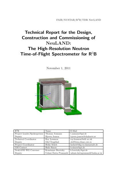
Technical Report for the Design,<br />
Construction and Commissioning of<br />
<strong>NeuLAND</strong>:<br />
The High-Resolution Neutron<br />
Time-of-Flight Spectrometer for R 3 B<br />
November 1, 2011<br />
R 3 B Name E-Mail<br />
Project Leader/Spokesperson Thomas Aumann t.aumann@gsi.de<br />
Deputy Bjoern Jonson bjoern.jonson@chalmers.se<br />
Technical Coordinator Roy Lemmon roy.lemmon@stfc.ac.uk<br />
Deputy Olof Tengblad olof@iem.cfmac.csic.es<br />
Project Coordinator Heiko Scheit hscheit@ikp.tu-darmstadt.de<br />
GSI Contact Haik Simon h.simon@gsi.de<br />
<strong>NeuLAND</strong> WG Convener Konstanze Boretzky k.boretzky@gsi.de<br />
Deputy Ushasi Datta Pramanik ushasi.dattapramanik@saha.ac.in
The R 3 B Collaboration<br />
Brazil<br />
University of Sao Paulo: Alinka Lepine-Szily<br />
Canada<br />
Saint Mary’s University Halifax: Rituparna Kanungo<br />
TRIUMF Vancouver: Reiner Krücken<br />
China<br />
Institute of Modern Physics Lanzhou: Ruofu Chen, Songlin Li, Hushan Xu, Yu-Hu<br />
Zhang<br />
Denmark<br />
Arhus University: Dmitri Fedorov, Hans Fynbo, Aksel Jensen, Karsten Riisager<br />
VTT: Simo Eränen, Juha Kalliopuska<br />
Finland<br />
France<br />
CEA/DAM Bruyères-le-Châtel: Farouk Aksouh, Audrey Chatillon, Julien Taieb<br />
CEA/DSM/IRFU Saclay: Alain Boudard, Diane Dore, Bernard Gastineau, Wolfram<br />
Korten, Philippe Legou, Sylvie Leray, Stefano Panebianco<br />
GANIL: David Boilley, Wolfgang Mittig, Fanny Rejmund, Patricia Roussel-Chomaz,<br />
Herve Savajols, Christelle Schmitt<br />
IPN Orsay: Bernard Genolini<br />
2
Germany<br />
EMMI and FIAS: Enrico Fiori, Bastian Löher, Deniz Savran<br />
GSI Darmstadt: Yuliya Aksyutina, Denis Bertini, Konstanze Boretzky, Peter Egelhof,<br />
Hans Emling, Hans Feldmeier, Hans Geissel, Jürgen Gerl, Kathrin Goebel, Magdalena<br />
Górska, Jörg Hehner, Michael Heil, Jan Hoffmann, Günter Ickert, Aleksandra Kelic-Heil,<br />
Ivan Kojouharov, Nikolaus Kurz, Karl-Heinz Langanke, Yvonne Leifels, Thomas Neff,<br />
Chiara Nociforo, Maria Valentina Ricciardi, Dominic Rossi, Thomas Roth, Takehiko<br />
Saito, Karl-Heinz Schmidt, Haik Simon, Klaus Sümmerer, Wolfgang Trautmann, Helmut<br />
Weick, Martin Winkler<br />
Helmholtz-Zentrum Dresden-Rossendorf: Daniel Bemmerer, Zoltan Elekes, Arnd Junghans,<br />
Mathias Kempe, Manfred Sobiella, Daniel Stach, Andreas Wagner, Jörn Wüstenfeld,<br />
Dmitry Yakorev<br />
TU Darmstadt: Leyla Atar, Thomas Aumann, Timo Bloch, Christoph Caesar, Joachim<br />
Enders, Diego Gonzalez-Diaz, Marcel Heine, Matthias Holl, Alexander Ignatov, Oleg<br />
Kiselev, Dmytro Kresan, Thorsten Kröll, Alina Movsesyan, Manfred Mutterer, Valerii<br />
Panin, Stefanos Paschalis, Marina Petri, Norbert Pietralla, Achim Richter, Heiko Scheit,<br />
Mirko von Schmid, Linda Schnorrenberger, Philipp Schrock, Stefan Typel, Vasily Volkov,<br />
Felix Wamers<br />
TU Dresden: Thomas Cowan, Marko Röder, Kai Zuber<br />
TU Munich: Michael Bendel, Michael Böhmer, Thomas Faestermann, Roman Gernhäuser,<br />
Walter Henning, Reiner Krücken, Tudi Le Bleis, Olga Lepyoshkina, Max Winkel, Sonja<br />
Winkler<br />
University of Cologne: Jannis Endres, Andreas Hennig, Vassili Maroussov, Lars Netterdon,<br />
Peter Reiter, Andreas Zilges<br />
University of Frankfurt: Sebastian Altstadt, Olga Ershova, Christoph Langer, Christian<br />
Müntz, Ralf Plag, René Reifarth, Kerstin Sonnabend, Meiko Volknandt, Christine<br />
Wimmer<br />
University of Gießen: Horst Lenske<br />
Unversity of Mainz: Jens Volker Kratz<br />
Hungary<br />
ATOMKI: Margit Csatlós, Zoltán Elekes, Zsolt Fülöp, János Gulyás, Attila Krasznahorkay,<br />
László Stuhl, János Timár, Tamás Tornyi<br />
University of Budapest:<br />
Ákos Horváth<br />
3
India<br />
AM University Aligarh: Rajeshwari Prasad, Manoj Kumar Sharma , Pushpendra Pal<br />
Singh<br />
BARC Mumbai: S. Kailas, Kripamay Mahata, Aradhana Shrivastava<br />
SINP Kolkata: Bijay Agrawal, Padmanava Basu, Pratap Bhattacharya, Sudeb Bhattacharya,<br />
Santosh Chakraborty, Sujib Chatterjee, Ushasi Datta Pramanik, Pradipta<br />
Kumar Das, Janaki Panja, Anisur Rahaman, Jayati Ra, Tinku Sinha<br />
Tata Institute: Rudrajyoti Palit<br />
RCNP Osaka: Isao Tanihata<br />
Japan<br />
Tokyo Institute of Technology: Takashi Nakamura<br />
University of Bergen: Jan Vaagen<br />
Norway<br />
Poland<br />
IFJ PAN Cracow: Bronislaw Czech, Stanislaw Kliczewski, Maria Kmiecik, Jerzy Lukasik,<br />
Adam Maj, Piotr Pawlowski, Miroslaw Zieblinski<br />
University of Cracow: Reinhard Kulessa, Wladyslaw Walus<br />
Portugal<br />
LIP Coimbra: Alberto Blanco, Paulo Fonte, Luis Lopes, Rui F. Marques<br />
University of Lisbon: Daniel Galaviz Redondo, Ana Henriques, Jorge Machado, Pamela<br />
Teubig, Paulo Velho<br />
UTL Lisbon: Raquel Crespo<br />
Romania<br />
Horia Hulubei National Institute of Physics: Mihai Stanoiu<br />
Institute of Space Sciences Bucharest: Madalin Cherciu, Maria Haiduc, Dumitru Hasegan,<br />
Mihai Potlog, Emil Stan<br />
4
INR Moscow: Alexander Botvina<br />
Russia<br />
Ioffe PTI St. Petersburg: Yuri Tuboltsev, Elena Verbitskaya<br />
IPPE Obninsk: Anatoly V. Ignatyuk<br />
JINR Dubna: Irina Egorova, Sergey N. Ershov, Andrey Fomichev, Mikhail Golovkov,<br />
Alexander V. Gorshkov, Leonid Grigorenko, Sergey Krupko, Yulia Parfenova, Sergey<br />
Sidorchuk<br />
PNPI Gatchina: Georgy Alkhazov, Vladimir Andreev, Andrey Fetisov, Victor Golovtsov,<br />
Anatolii Krivshich, Lev Uvarov, Vladimir Vikhrov, Sergey Volkov, Andrey Zhdanov<br />
RRC Kurchatov Institute Moscow: Boris Danilin, Leonid Chulkov, Alexei Korsheninnikov,<br />
Eugenii Kuzmin, Aleksey Ogloblin<br />
Saudi Arabia<br />
National Center for Mathematics and Physics: Hamoud AlHarbi, Nasser AlKhomashi,<br />
Abdulrahman AlGhamdi, Abdulrahman Maghrabi<br />
King Saud University: Khalid Kezzar, Safar AlGhamdi, Mohamed AlGarawi, Farouk<br />
Aksouh<br />
Slovakia<br />
Slovak Academy of Sciences: Martin Veselsky<br />
Spain<br />
IEM-CSIC Madrid: Maria José Garcia Borge, Eduardo Garrido, Enrique Nacher, Angel<br />
Perea, Guillermo Ribeiro, José Sanchez del Rio, Jorge Sanchez Rosado, Olof Tengblad<br />
IFIC Valencia: Alejandro Algora, Berta Rubio, José L. Tain<br />
Universidad Complutense of Madrid: Samuel España, Luis M. Fraile, Jose Udias-Moinelo<br />
University of Santiago de Compostela: Héctor Alvarez-Pol, Francesc Ayyad, José Benlliure,<br />
Manuel Caamaño, Dolores Cortina-Gil, Paloma Díaz, Ignacio Durán, Beatriz<br />
Fernández-Domínguez, Martín Gascón, David González-Caamaño, Carlos Paradela, Noelia<br />
Montes, Juan Ramón Pereira, Benjamin Pietras<br />
University of Vigo: Enrique Casarejos<br />
UPC Barcelona: Francisco Calvino<br />
5
Sweden<br />
Chalmers University: Christian Forssén, Johan Gill, Julius Hagdahl, Andreas Heinz,<br />
H˚akan Johansson, Björn Jonson, Thomas Nilsson, Goran Nyman, Natalia Shulgina,<br />
Ronja Thies, Staffan Wranne, Mikhail Zhukov<br />
KTH Stockholm: Bo Cederwall, Stanislav Tashenov<br />
Lund University: Vladimir Avdeichikov, Joakim Cederkall, Pavel Golubev, Lennart<br />
Isaksson, Bo Jakobsson<br />
CERN: Vladimir Eremin<br />
Switzerland<br />
The Netherlands<br />
KVI: Nasser Kalantar, Ali Najafi, Catherine Rigollet, Branislav Streicher<br />
University of Groningen: Jarno Van de Walle<br />
United Kingdom<br />
CCLRC Daresbury Laboratory: Patrick Coleman-Smith, Marc Labiche, Ian Lazarus,<br />
Roy Lemmon, Simon Letts, Vic Pucknell, John Simpson<br />
University of Birmingham: Nick Ashwood, Matthew Barr, Martin Freer<br />
University of Edinburgh: Tom Davinson, Phil Woods<br />
University of Liverpool: Marielle Chartier, J. Cresswell, Simon Gannon, Paul Nolan,<br />
M. Norman, J. Sampson, Janet Sampson, D. Seddon, T. Stanios, Jonathan Taylor, J.<br />
Thornhill, D. Wells<br />
University of Manchester: David Cullen, Sean Freeman<br />
University of Surrey: Jim Al-Khalili, Carlo Barbieri, Wilton Catford, William Gelletly,<br />
Ron Johnson, Zsolt Podolyak, Patrick Regan, Arnau Rios, Edward Simpson, Paul<br />
Stevenson, Jeffrey Tostevin<br />
University of York: Charles Barton<br />
Argonne National Laboratory: Jerry Nolen<br />
EMMI/JINA: Justyna Marganiec<br />
USA<br />
Michigan State University: Bradley Sherrill, Remco Zegers<br />
Texas A&M University Commerce: Carlos Bertulani<br />
6
Contents<br />
Executive Summary 11<br />
1. Introduction and Overview 13<br />
1.1. <strong>NeuLAND</strong> – A Key Instrument of R 3 B for High-Resolution Multi-Neutron<br />
Detection . . . . . . . . . . . . . . . . . . . . . . . . . . . . . . . . . . . . 13<br />
1.2. <strong>NeuLAND</strong> Design Goals – General Remarks . . . . . . . . . . . . . . . . . 16<br />
2. Physics Scenarios: Requirements for <strong>NeuLAND</strong> 19<br />
2.1. Evolution of the Collective Response of Exotic Nuclei . . . . . . . . . . . 19<br />
2.2. Dipole Strength at the Particle Threshold . . . . . . . . . . . . . . . . . . 21<br />
2.3. Light Exotic Systems - Unbound States and Multi-Neutron Configurations 22<br />
2.4. Quasi-Free Scattering . . . . . . . . . . . . . . . . . . . . . . . . . . . . . 24<br />
2.5. Fission and Multifragmentation . . . . . . . . . . . . . . . . . . . . . . . . 26<br />
2.6. Flow and Equation of State . . . . . . . . . . . . . . . . . . . . . . . . . . 27<br />
3. Summary of <strong>NeuLAND</strong> Prototype Results 29<br />
3.1. Scintillator Concept . . . . . . . . . . . . . . . . . . . . . . . . . . . . . . 29<br />
3.2. Studies with Fast Protons . . . . . . . . . . . . . . . . . . . . . . . . . . . 29<br />
3.3. Studies with 31 MeV Electrons . . . . . . . . . . . . . . . . . . . . . . . . 31<br />
3.4. Other Approaches . . . . . . . . . . . . . . . . . . . . . . . . . . . . . . . 34<br />
4. Monte Carlo Simulations 35<br />
4.1. Overview and Comparison of the Various Simulation Codes . . . . . . . . 35<br />
4.1.1. Simulation Frameworks . . . . . . . . . . . . . . . . . . . . . . . . 35<br />
4.1.2. Neutron Data Validation . . . . . . . . . . . . . . . . . . . . . . . 37<br />
4.2. From a Passive Converter to a Fully-Active Scintillator Concept . . . . . 43<br />
4.3. Effect of Granularity and Timing Properties for a Fully-Active Detector . 45<br />
4.4. Light-Transport Simulations . . . . . . . . . . . . . . . . . . . . . . . . . 48<br />
4.5. Scintillator Studies of Full-Size <strong>NeuLAND</strong> . . . . . . . . . . . . . . . . . 51<br />
4.5.1. One-Neutron Response . . . . . . . . . . . . . . . . . . . . . . . . 52<br />
4.5.2. Multi-Neutron Response . . . . . . . . . . . . . . . . . . . . . . . . 52<br />
4.5.3. Neutron Tracking . . . . . . . . . . . . . . . . . . . . . . . . . . . 55<br />
4.5.4. Physics Cases . . . . . . . . . . . . . . . . . . . . . . . . . . . . . 59<br />
5. Technical Specifications and Design Details of <strong>NeuLAND</strong> 65<br />
5.1. Final Detector Parameters . . . . . . . . . . . . . . . . . . . . . . . . . . . 65<br />
7
5.2. Structure of the <strong>NeuLAND</strong> Submodule . . . . . . . . . . . . . . . . . . . . 65<br />
5.2.1. Material, Sizes and Wrapping . . . . . . . . . . . . . . . . . . . . 65<br />
5.2.2. Light Guides . . . . . . . . . . . . . . . . . . . . . . . . . . . . . . 65<br />
5.2.3. Light Readout . . . . . . . . . . . . . . . . . . . . . . . . . . . . . 66<br />
5.3. Full Detector Assembly . . . . . . . . . . . . . . . . . . . . . . . . . . . . 67<br />
5.3.1. Grouping of Submodules — Double Planes . . . . . . . . . . . . . 67<br />
5.3.2. Full Detector Setup . . . . . . . . . . . . . . . . . . . . . . . . . . 70<br />
5.4. Peripheral Systems . . . . . . . . . . . . . . . . . . . . . . . . . . . . . . 73<br />
5.4.1. Read-Out Electronics - TacQuila . . . . . . . . . . . . . . . . . . . 73<br />
5.4.2. High-Voltage Distribution System . . . . . . . . . . . . . . . . . . 74<br />
5.4.3. Controls . . . . . . . . . . . . . . . . . . . . . . . . . . . . . . . . . 76<br />
6. Radiation Environment and Safety Issues 77<br />
7. Production, Quality Assurance and Acceptance Tests 79<br />
8. Calibration 81<br />
8.1. Calibration with Fast Neutrons . . . . . . . . . . . . . . . . . . . . . . . . 81<br />
8.1.1. Calibration of a Subset of <strong>NeuLAND</strong> Modules . . . . . . . . . . . 81<br />
8.1.2. Characterization of Neutron Interactions with the Full-Size Detector 84<br />
8.2. Cosmic Ray Tracking in <strong>NeuLAND</strong> for Adjustment and Calibration . . . 84<br />
9. Infrastructure 87<br />
10.Installation procedure, its Time Sequence, Necessary Logistics from A to Z<br />
including Transportation 89<br />
11.Cost and Funding 91<br />
11.1. Cost Estimate . . . . . . . . . . . . . . . . . . . . . . . . . . . . . . . . . . 91<br />
11.2. Funding Scheme . . . . . . . . . . . . . . . . . . . . . . . . . . . . . . . . 91<br />
12.Time Schedule Table and Milestones 93<br />
13.Organization and Distribution of Responsibilities 95<br />
A. <strong>NeuLAND</strong> Working Group Members 97<br />
B. Neutron MRPC Results in Details 99<br />
B.1. Principle of Operation of an MRPC-Based Neutron Detector with a Thick<br />
Iron Converter . . . . . . . . . . . . . . . . . . . . . . . . . . . . . . . . . 99<br />
B.2. 40 MeV Single Electron Test Facility at ELBE . . . . . . . . . . . . . . . . 101<br />
B.3. Design Issues Addressed with 40 cm × 20 cm Prototypes . . . . . . . . . . 104<br />
B.4. Construction and Test of a Full-Size 200 cm × 50 cm Prototype . . . . . . 105<br />
B.5. Monte Carlo Simulations . . . . . . . . . . . . . . . . . . . . . . . . . . . . 106<br />
B.6. Further MRPC Prototype and Offline Tests . . . . . . . . . . . . . . . . . 110<br />
8
B.7. MRPC Solution using Glass as Converter . . . . . . . . . . . . . . . . . . 112<br />
B.8. Summary and Outlook . . . . . . . . . . . . . . . . . . . . . . . . . . . . . 112<br />
Bibliography 115<br />
9
Executive Summary<br />
The R 3 B (Reactions with Relativistic Radioactive Beams) experiment at <strong>FAIR</strong> will be<br />
the only facility worldwide providing the capability for kinematically complete measurements<br />
of reactions with relativistic heavy-ion beams of short-lived nuclei up to about<br />
1 AGeV. These measurements require a high resolution to allow for a comprehensive experimental<br />
investigation of fundamental science questions related to nuclear structure,<br />
astrophysics, and reactions with neutron-proton asymmetric nuclei. The experimental<br />
setup has been designed and will be built by the R 3 B collaboration on the basis of more<br />
than 20 years of experience with the reaction setup LAND at GSI. The newly designed<br />
instrumentation thereby overcomes major limitations of the present setup. The main<br />
design goals emerging from the physics cases are the applicability of the experimental<br />
approach to energetic beams maintaining the high resolution, as well as the extension<br />
of the physics program, i.e., the capability to measure a large variety of reaction types.<br />
The beams provided by Super-FRS at <strong>FAIR</strong> will be more neutron-rich than presently<br />
available, up to uranium. Consequently, high beam energies are needed in order to ensure<br />
fully-stripped ions for heavy beams. At the same time, the capability to detect<br />
multi-neutron events is required due to the low thresholds of neutron-rich nuclei.<br />
<strong>NeuLAND</strong> (new Large-Area Neutron Detector) is the next-generation neutron detector<br />
designed for R 3 B which meets all requirements defined by the ambitious physics program<br />
proposed for the R 3 B facility. <strong>NeuLAND</strong> features a high detection efficiency, a high<br />
resolution, and a large multi-neutron-hit resolving power. This is achieved by a highly<br />
granular design of plastic scintillators, avoiding insensitive converter material. The detector<br />
will consist of 3000 individual submodules with a size of 5×5×250 cm 3 , arranged<br />
in 30 double planes with 100 submodules providing an active face size of 250×250 cm 2<br />
and a total depth of 3 m. <strong>NeuLAND</strong> can be divided into two detectors for special applications<br />
and will be placed at different distances from the target, in order to meet specific<br />
experimental demands.<br />
The neutron detector <strong>NeuLAND</strong> is an integral part of the R 3 B experiment, and is<br />
the key instrument for a major part of the physics program. The main design goals<br />
comprise a one-neutron detection efficiency above 95% in a wide energy range and a full<br />
acceptance corresponding to an angular coverage of ±80 mrad. The desired resolutions<br />
for momenta and thus the excitation energies, as described in detail in chapter 2, lead to<br />
the required spatial resolutions of σx,y,z ≤ 1.5 cm and to a time resolution of σt ≤ 150 ps<br />
for the standard distance between detector and target of 15.5 m. When placed at a<br />
distance of 35 m, an excitation-energy resolution of less than 20 keV(!) will be reached<br />
for an excitation energy of 100 keV above threshold for a beam energy of 600 AMeV.<br />
11
Apart from the excellent energy resolution of <strong>NeuLAND</strong>, the enhanced multi-neutron<br />
recognition capability with an efficiency of up to 60% for a reconstructed four-neutron<br />
event will constitute a major step forward.<br />
The presented design is the result of several years of R&D studies. Summaries of prototype<br />
tests and simulations are presented in chapters 3 and 4, respectively. Different<br />
design concepts have been followed, including converter-based solutions, e.g., a detector<br />
based on steel converter plus charged-particle detection with resistive-plate chambers<br />
(RPC). The RPC concept has been ruled out mainly because of its insufficient multineutron<br />
detection capability. A fully active detector with calorimetric properties has<br />
turned out to be the best solution. Submodules have been tested with proton and electron<br />
beams resulting in time resolutions of better than the required σt ≤ 150 ps, even<br />
with inexpensive photomultipliers. In accordance with simulations, improved timing<br />
properties have been obtained with optimized light guides.<br />
Extensive simulation studies have been performed leading to the final design. Different<br />
frameworks have been applied such as GEANT and FLUKA, leading to a remarkable<br />
agreement. The good accordance of simulations with available data leads to a consistent<br />
prediction of the neutron response for the detector. A fully-active detector design is<br />
required to provide the unambiguous identification of primary neutron interactions, the<br />
large efficiency at lower neutron energies and the high multi-neutron resolving power,<br />
the latter being due to its calorimetric properties. The effect of the granularity and<br />
the time resolution of the detector has been investigated in detail (section 4.3), leading<br />
to the most cost-effective solution presented here, which still meets the required design<br />
criteria. The final performance is demonstrated in section 4.5 for several physics cases.<br />
The details of the technical realization including mechanics, readout electronics, tests,<br />
calibrations, as well as the construction procedure are summarized in chapters 5 to 10.<br />
A detailed estimate of the investment cost for the construction is given in chapter 11.<br />
Several groups of the R 3 B collaboration will contribute to the construction of the Neu-<br />
LAND detector. The final assembly will take place at the GSI/<strong>FAIR</strong> site. We expect the<br />
beginning of construction in 2012, as soon as funding will be available. The construction<br />
of the full detector will take about 3.5 years, allowing for first experiments with the<br />
complete detector in 2016. An important milestone will be met by using a 20% detector<br />
for physics experiments in the end of 2014 in Cave C at GSI, which will already profit<br />
from an improved resolution for neutron detection.<br />
We consider the risk for technical difficulties in the production or for an insufficient<br />
performance of the detector to be negligible. The design based on fully-active scintillators<br />
with photomultiplier readout is rather robust and the simulations, on which our<br />
design decisions are based upon, have been verified against each other and experimental<br />
data. The fully-equipped detector – after full commissioning and first production runs<br />
in Cave C – will move to its final location in the R 3 B hall at the <strong>FAIR</strong> site in 2017,<br />
being fully operational for physics experiments in 2018 when Super-FRS will deliver first<br />
beams at <strong>FAIR</strong>.<br />
12
1. Introduction and Overview<br />
1.1. <strong>NeuLAND</strong> – A Key Instrument of R 3 B for<br />
High-Resolution Multi-Neutron Detection<br />
The acronym R 3 B stands for Reactions with Relativistic Radioactive Beams. The<br />
R 3 B experiment will be installed at the high-energy branch focal-plane of the Super-<br />
FRagment-Separator Super-FRS at the <strong>FAIR</strong> Facility for Antiproton and Ion Research.<br />
The R 3 B activity is embedded into the NUSTAR (NUclear STructure, Astrophysics and<br />
Reactions) pillar of the <strong>FAIR</strong> experimental program. The design and construction of the<br />
R 3 B facility is being pursued within a large international collaboration, the R 3 B collaboration,<br />
which is a consortium of more than 200 scientists from more than 20 countries.<br />
The physics cases and the conceptual layout of the experiment including its instrumental<br />
parts have been laid out in the Conceptual Design Report for <strong>FAIR</strong> [CDR-01] in 2001<br />
and in more technical detail in the R 3 B Technical Proposal [R3B-05] in 2005. Since<br />
then, an extensive R&D program has been pursued which led to the final design of the<br />
different detection components. In this report, we describe in detail the technical design<br />
of the neutron detector <strong>NeuLAND</strong> (New Large Area Neutron Detector). This detector<br />
serves as a high-resolution time-of-flight spectrometer for neutrons in the energy range<br />
from 100 to 1000 MeV. The superior time and position resolution of this detector in<br />
conjunction with an excellent resolving power for multi-neutron events is the key for the<br />
realization of the ambitious physics program of R 3 B and will enable the investigation of<br />
nuclear reactions with unprecedented precision.<br />
The R 3 B experiment will enable kinematically complete measurements of reactions with<br />
relativistic beams up to energies of approximately 1 AGeV. (The upper limit in energy is<br />
defined by the maximum magnetic rigidity of 20 Tm of the Super-FRS). The flexibility of<br />
the setup with its detection systems allows us to accommodate experiments investigating<br />
different types of reactions and physics cases. An overview on the physics subjects to<br />
be investigated has been given in the Conceptual Design Report [CDR-01]. In the<br />
next chapter we discuss a selection of physics cases for which the neutron detector<br />
<strong>NeuLAND</strong> and its performance play an important role, which could be summarized in<br />
the question: How do nuclear properties evolve as a function of isospin? This includes<br />
nuclear-structure properties of short-lived nuclei with extreme neutron-to-proton ratios<br />
as well as properties of asymmetric nuclear matter. Both, the experimental answers<br />
to this question as well as a fundamental understanding from a theoretical point of<br />
view, form the basis to the understanding and description of astrophysical objects and<br />
13
processes in the universe, such as the properties of neutron stars and the synthesis of the<br />
heavy elements. R 3 B will constitute a unique setup to investigate these topics utilizing<br />
relativistic beams. The advantages of utilizing high-energy beams are many-fold. First,<br />
the production, separation, and identification of radioactive beams at high energies is<br />
very efficient due to the kinematical forward focussing and the possibility to use thick<br />
targets. Second, it also enables a clean separation of even heavy beams with masses<br />
A ≥ 200 due to the fact that ions are fully stripped, a pre-requisite for the magnetic<br />
analysis and separation of heavy ions. Similar arguments hold for the measurement<br />
of secondary reactions with these beams. R 3 B will be the first experiment which will<br />
allow a kinematically complete measurement of peripheral reactions with such heavy ion<br />
beams including the coincident detection and identification of the heavy residues as well<br />
as neutrons and photons. Other advantages of the high beam energy are related to the<br />
reaction mechanisms, which become simpler, permitting reliable model description, at<br />
higher beam energies. At high velocity, reactions can be accurately described by theory,<br />
nuclear-structure observables are less entangled with the reaction mechanism, and can<br />
thus be deduced more precisely.<br />
In this report we do not describe the complete R 3 B experimental setup with its instrumentation<br />
but we would like to refer the reader to the R 3 B Technical Proposal [R3B-05].<br />
However, to understand the context, we briefly mention the development and construction<br />
status of the main components of the R 3 B setup, as shown in figure 1.1.<br />
Key instruments besides <strong>NeuLAND</strong>, are the photon and particle calorimeter CALIFA,<br />
the silicon tracker R 3 B-Si-TRACKER, and the super-conducting large-acceptance dipole<br />
R 3 B-GLAD. In addition, several charged-particle detectors are used for beam tracking,<br />
∆E and time-of-flight measurements. The CALIFA detector consists of two parts, the<br />
forward end-cap and the barrel part. A Technical Design Report for the barrel part of<br />
CALIFA is being submitted in parallel to this report. Construction is foreseen to start<br />
in 2012. The Technical Design of the end-cap is still ongoing and will be finalized in<br />
2013. The target recoil detector is being designed by a consortium of institutes from the<br />
UK under the leadership of Daresbury laboratory. The funds for the R&D and the final<br />
construction are secured by the UK funding agencies and the complete detector will be<br />
available for experiments in 2016. The construction of the superconducting dipole magnet<br />
has already started at CEA Saclay and the cold mass including the superconducting<br />
coils have been already assembled. The completion and delivery of the device is foreseen<br />
for the end of 2012. The magnet will then be installed in Cave C at the present GSI<br />
facility.<br />
The challenges of performing nuclear-structure and reaction experiments at relativistic<br />
beam velocities are related to the high magnetic rigidity of the ions and the demands<br />
on the overall resolution of the detection system. The experiment has to resolve excitation<br />
energies in the 100 keV domain populated in a reaction with, e.g., a 132 Sn beam<br />
(1 AGeV) with a momentum of 220 GeV/c. The precursor experiment of R 3 B, the<br />
ALADIN-LAND setup at GSI, on which the concept of R 3 B is based, does not have these<br />
capabilities. Although very successful during the past 20 years, the main limitations of<br />
14
RIB from<br />
Super-FRS<br />
R 3 B-Si-TRACKER<br />
CALIFA<br />
R3B Start version 2016<br />
Heavy<br />
fragments<br />
Protons<br />
R 3 B-GLAD<br />
<strong>NeuLAND</strong><br />
Figure 1.1.: The R 3 B setup in its startup phase 2016 with its main components: the silicon<br />
tracker R 3 B-Si-TRACKER, the calorimeter CALIFA, the dipole magnet<br />
R 3 B-GLAD and the neutron time-of-flight spectrometer <strong>NeuLAND</strong>.<br />
the present setup are the limited magnetic rigidity, the limited resolution in momentum<br />
for fragments and neutrons, the lack of good resolution for γ-ray detection (mainly due<br />
to the Doppler broadening) and the limited capability to detect multi-neutron events.<br />
Here, <strong>NeuLAND</strong> will have a key role. A substantial improvement in resolution of about<br />
a factor of three compared to LAND will result in improved invariant-mass resolution,<br />
even with the higher beam energies up to approximately 1 AGeV. Complementary, lower<br />
beam energies and a large time-of-flight path for neutrons will enable high-resolution experiments<br />
for special cases. An excitation energy resolution down to below σ=20 keV (!)<br />
around the particle threshold will allow the investigation of narrow resonances as well as<br />
a precise determination of differential cross sections at low excitation energies relevant<br />
for the synthesis processes of elements in the universe. The unprecedented multi-neutron<br />
hit capability of the new design will be the basis for studying very neutron-rich nuclei,<br />
whose emission thresholds become low. Another highlight related to the multi-neutron<br />
detection capability is the study of the most neutron-rich systems – the unbound continuum<br />
states beyond the neutron dripline like, for instance, the bench mark cases 28 O<br />
15
decaying into 24 O plus 4 neutrons and the tetra-neutron system. In the next section we<br />
summarize the capabilities and design goals of <strong>NeuLAND</strong>. In chapter 2 we provide a more<br />
detailed view of the various physics cases of R 3 B with emphasis on those cases where<br />
the performance of the newly designed <strong>NeuLAND</strong> is key to crossing borders into new<br />
frontiers, i.e., entering ”Neuland” (terra incognita) in physics with radioactive beams.<br />
1.2. <strong>NeuLAND</strong> Design Goals – General Remarks<br />
The detection of fast neutrons plays a crucial role for the exploration of light and heavy<br />
exotic nuclei towards the neutron dripline. Since the neutron separation thresholds decrease<br />
with increasing neutron-proton asymmetry, the emission of several neutrons after<br />
excitation is the dominant decay process. Neutrons emitted from projectiles with high<br />
velocities in the laboratory frame are kinematically strongly forward focussed, although<br />
isotropically emitted in the projectile rest frame. This allows for a very efficient coverage<br />
of the full solid angle with moderate detector sizes. The excitation energy of the<br />
projectile can be determined, using the invariant-mass technique, from measurements of<br />
the momenta of all emitted particles. The neutron momenta are determined from the<br />
measured position of the interaction in the neutron detector and the time-of-flight from<br />
the target to the neutron detector. The desired resolutions for momenta and thus the<br />
excitation energies, see details in chapter 2, lead to the required spatial resolutions of<br />
σx,y,z ≤ 1.5 cm and a time resolution of σt ≤ 150 ps. The main design goals comprise,<br />
besides the improved resolution, a detection efficiency above 95% for single neutrons<br />
for a wide energy range, a large geometrical acceptance and an excellent multi-neutron<br />
hit reconstruction efficiency. The major achievements in performance, compared to the<br />
present LAND detector, are an improved resolution by a factor of three, the extension of<br />
the very high efficiency for neutrons down to lower energies, and the substantial improvement<br />
of the multi-neutron reconstruction efficiency from a few percent up to 60 percent.<br />
The latter will be a major and necessary advantage for future studies with more neutronrich<br />
systems including nuclear states beyond the neutron dripline. The performance of<br />
the detector is described in great detail in this report on the basis of extensive simulations<br />
and prototype tests. Here, we give a brief overview on the main features with some<br />
examples including large acceptance, high resolution, a large multi-neutron-hit resolving<br />
power, and high efficiency in a very wide energy window.<br />
The active area of the detector of 250 × 250 cm 2 allows to cover the full acceptance<br />
of ±80 mrad determined by the gap of the dipole magnet if the detector is placed<br />
15.5 m downstream of the target. This solid-angle coverage corresponds to a 100%<br />
acceptance (4π) measurement of neutrons with kinetic energies up to around 5 MeV in<br />
the center-of-mass (CM) frame if emitted from a projectile fragment with a kinetic energy<br />
of 600 AMeV. This has to be compared with a typical neutron energy distribution, e.g.,<br />
a Maxwellian distribution of a statistical decay, which peaks at kinetic energies of 1 to<br />
2 MeV and contains more than 90% of the events within the 5 MeV coverage. At higher<br />
beam energies, either a larger acceptance can be chosen (up to about 10 MeV neutron<br />
16
energy at 1 AGeV), or the detector can be placed further downstream to increase the<br />
resolution by keeping the nominal acceptance of up to 5 MeV neutrons. At 1 AGeV,<br />
a 5 MeV neutron emitted perpendicular to the beam axis will appear at 57 mrad in<br />
the laboratory frame, which is fully covered by <strong>NeuLAND</strong> at a distance of 22 m to the<br />
target.<br />
In the full-acceptance mode (15.5 m distance), the position resolution of 1.5 cm corresponds<br />
to a resolution in transverse momentum of 10 −3 relative to the total momentum<br />
of the neutron. The resulting invariant-mass resolution depends on the beam energy and<br />
the excitation energy. For the 600 AMeV case, this corresponds to around 60 keV energy<br />
resolution at an excitation energy of 1 MeV above the neutron emission threshold. The<br />
longitudinal component of the resolution is more complicated depending not only on<br />
beam energy and excitation energy, but also on the emission angle. Simulations have<br />
shown that the excellent excitation-energy resolution stemming from the position measurement<br />
can be maintained if the time resolution is better than 150 ps. The ultimate<br />
resolution can be reached by placing the detector at the longest possible distance to the<br />
target, which is 35 m in the R3B/<strong>FAIR</strong> experimental hall. Then a resolution of better<br />
than 20 keV can be reached at 600 AMeV for an excitation energy 100 keV above the<br />
neutron threshold. This means that it will be possible to measure the differential (γ, n)<br />
cross section in an energy range corresponding to the stellar temperature window. The<br />
measurement of narrow resonances close to the threshold of unbound nuclei beyond the<br />
dripline is another example where the ultimate resolution is required.<br />
Apart from the excellent energy resolution of <strong>NeuLAND</strong>, a major step forward is the<br />
multi-neutron recognition capability of the new design. A reliable reconstruction of the<br />
momentum vectors for several neutrons hitting the detector will be achieved even if the<br />
neutrons impinging on the detector are spatially not well separated. An efficiency, for<br />
instance, of up to 60% can be reached for a reconstructed four-neutron event. This is an<br />
important achievement for many physics cases including the study of neutron droplets<br />
and nuclear systems beyond the dripline in general. Also for giant resonance studies,<br />
or excitations in general, the multi-hit recognition becomes essential for neutron-rich<br />
systems. Even for medium-heavy and heavy nuclei, Super-FRS at <strong>FAIR</strong> will deliver<br />
neutron-rich beams with low neutron separation thresholds causing the multi-neutron<br />
decay channel being the dominant one. Other examples for reaction studies involving<br />
the detection of several neutrons are fission and multifragmentation.<br />
Last but not least we mention the large neutron energy range which is covered by Neu-<br />
LAND with high efficiency. Here, the goal is to improve the detection efficiency and<br />
response compared to LAND for lower energies down to approximately 50 to 200 MeV.<br />
Similar as for the multi-neutron capability, this goal can be achieved due to the fullyactive<br />
scintillator concept omitting passive converter material. The efficiency of >95%<br />
at high energies drops only to 90% for 200 MeV neutrons. This is particularly important<br />
for the quasi-free scattering program. <strong>NeuLAND</strong> will allow the energy-resolved detection<br />
of knocked out neutrons in (p,pn) reactions at angles around 45 degrees.<br />
17
2. Physics Scenarios: Requirements for<br />
<strong>NeuLAND</strong><br />
In the following sections we detail the demands for the detection of fast neutrons derived<br />
from the main types of experiments within the broad R 3 B physics program. For a more<br />
detailed description of the overall R 3 B physics programme we refer to the Conceptual<br />
Design Report for <strong>FAIR</strong> [CDR-01] and the R 3 B Technical Proposal [R3B-05] and references<br />
therein. <strong>NeuLAND</strong> will be located downstream from the target. In the full<br />
acceptance mode, the distance from the target is chosen such, that the face-size of the<br />
detector covers the same angular range as the yoke of the dipole magnet R 3 B-GLAD,<br />
namely 80 mrad. For a detector of 2.5×2.5 m 2 face-size the full-acceptance distance is<br />
15.5 m downstream from the target. For some applications, see e.g. section 2.2, the<br />
highest possible resolution is demanded. Here we profit from the length of the R 3 B cave<br />
allowing to position the detector up to 35 m downstream. As a third option <strong>NeuLAND</strong>,<br />
or parts of <strong>NeuLAND</strong>, can be placed closer to the target for the detection of neutrons<br />
stemming from quasi-free scattering interactions, see section 2.4.<br />
2.1. Evolution of the Collective Response of Exotic Nuclei<br />
Electromagnetic excitation of exotic nuclei is a very powerful tool for exploring the evolution<br />
of collective phenomena like giant resonances, especially the giant dipole resonance<br />
(GDR) as a function of neutron-proton asymmetry [Har-01]. At beam energies of up to<br />
1000 AMeV, cross sections for dipole excitations are large, on the order of barn, and the<br />
excitation energies transferred reach up to approximately 20 MeV [Ber-85]. The LAND<br />
collaboration has played a pioneering role in this field discovering the double giant dipole<br />
resonance in stable nuclei [Bor-03], and more recently the pygmy mode in neutron-rich<br />
Sn isotopes [Adr-05]. The appearance of low-lying strength in exotic nuclei [Kli-07],<br />
[Wie-09], is particularly interesting from a nuclear structure point of view since its occurrence<br />
is interpreted as a consequence of neutron-proton asymmetry and the evolution<br />
of skin effects. Similar to the collective giant resonances, this so-called pygmy strength<br />
is related to bulk properties of nuclei and nuclear matter. Various, and partly contradictory,<br />
microscopic theoretical models describe this resonance as discussed in an overview<br />
by N. Paar et al. in Ref. [Paa-07] and references therein. It has been suggested, that the<br />
density dependence of the symmetry energy close to saturation density is correlated with<br />
the low-lying dipole strength in neutron-rich nuclei [Pie-06], very similar to the earlier<br />
reported correlation of the symmetry energy parameters to the neutron-skin thickness in<br />
19
heavy neutron-rich nuclei [Bro-00], [Hor-01]. A first attempt to extract the parameters<br />
describing the neutron-proton asymmetry part of the equation of state for nuclear matter<br />
from the measured low-lying dipole strength has been made by Kliemkiewicz et al.<br />
[Kli-07] and by Carbone et al. [Car-10]. Experimental data concerning the collective response<br />
of exotic nuclei including the giant resonances and the pygmy dipole strength are<br />
still rather scarce. The existing dipole strength measurements suffer from an insufficient<br />
response of the detector system.<br />
From the experimental point of view, there are several challenges to deal with. The<br />
heavy-ion induced electromagnetic excitation process requires high beam energies which<br />
in turn put high demands on the detection systems. The combination of a largeacceptance<br />
superconducting dipole with large field integral, a highly granular calorimeterlike<br />
photon detector together with a high-efficiency and high-resolution detection of<br />
neutrons make the R 3 B setup an ideal facility to study the collective response of exotic<br />
nuclei.<br />
The neutron detector has to be optimized for high detection efficiency and acceptance in<br />
the beam-energy region from 200 to 1000 AMeV. A variation of beam energy is necessary<br />
to disentangle dipole and quadrupole contributions to the excitation cross section. The<br />
lower energy of 200 AMeV will be used to study giant monopole resonances in neutronrich<br />
nuclei which are related to the incompressibility of asymmetric nuclear matter. We<br />
will use alpha scattering in inverse kinematics in an active He gas target which will be<br />
developed for these measurements. For heavy nuclei, like Pb, the beam energies around<br />
1 AGeV are necessary to allow for fully stripped ion beams. It is mandatory to apply<br />
a magnetic analysis for an identification of the fragments using a tracking system. So<br />
far, this has not been possible due to the limitations of the present detection devices.<br />
The improved resolution of <strong>NeuLAND</strong> will make a high-resolution detection of neutrons<br />
possible even at a laboratory energy of 1 AGeV.<br />
The kinetic energy of neutrons evaporated from collective states in the continuum follows<br />
usually a Maxwellian distribution with a maximum at approximately 1 to 2 MeV.<br />
An angular acceptance which allows detection of up to about 5 MeV kinetic energy is<br />
required to cover the full distribution. This requirement is met by the ±80 mrad acceptance<br />
defined by the gap of the dipole magnet and will be covered by the neutron<br />
detector. The envisaged position and time resolution of 1.5 cm and 150 ps for <strong>NeuLAND</strong><br />
will result in an excitation energy resolution of about 100 keV at an excitation energy<br />
of 1 MeV above the threshold (or 1 MeV kinetic energy of the neutron) for a 600 AMeV<br />
beam at a distance fulfilling the full-acceptance criterium. At 1 AGeV, the detector can<br />
be placed further away while providing the same acceptance and about the same energy<br />
resolution.<br />
The high intensities of radioactive beams provided by the Super-FRS at <strong>FAIR</strong> will<br />
push the frontier towards more neutron-rich systems. In such nuclei, the effects of<br />
asymmetry are magnified and the electromagnetic response of the nucleus reflects these<br />
isospin-related changes. The Pygmy resonance is one example, but also the dipole and<br />
quadrupole response as a whole change. The neutron-rich medium-mass nuclei which can<br />
20
e studied at R 3 B at <strong>FAIR</strong> include nuclei which are produced in explosive astrophysical<br />
scenarios where the heavy elements are synthesized in the r-process. While ground-state<br />
properties like masses and half-lives are the most important properties necessary for<br />
modeling the rapid neutron capture process in an equilibrium stage, it has been shown<br />
that for an accurate theoretical description of the r-process the dipole response of these<br />
nuclei plays an essential role in determining the final abundance of nuclei as observed<br />
in the solar system. A systematic change of the response of nuclei alters the result of<br />
the elemental synthesis significantly [Gor-98], [Rau-08]. An experimental and theoretical<br />
effort has to be undertaken in order to understand the response of these neutron-rich<br />
nuclei. Since the neutron separation energies for these nuclei are typically approximately<br />
one to two MeV only, the decay of excited projectiles involves many neutrons. In order<br />
to enable an invariant-mass analysis, the momentum vectors of the different neutrons<br />
have to be resolved. Typically around four neutrons from the decay of the GDR will<br />
have to be detected. <strong>NeuLAND</strong> will be the first detector which will be capable to satisfy<br />
such a demand. An efficiency for a correct detection of a four-neutron event of about<br />
60% is envisaged.<br />
2.2. Dipole Strength at the Particle Threshold<br />
Electromagnetic excitation of exotic nuclei is of importance as well from an astrophysical<br />
point of view as mentioned already in the previous section. While the paths of the nucleosynthesis<br />
processes like the r-, and rp-processes are essentially determined by nuclear<br />
masses and lifetimes, the final abundance patterns depend also on the (p,γ) and (n,γ)<br />
reaction rates. For the modeling of astrophysical processes with network calculations,<br />
the reaction rates are usually calculated using a standard dipole response of nuclei as an<br />
input to a Hauser-Feshbach calculation. It has been shown by Litvinova et al. [Lit-09]<br />
that for a microscopically calculated dipole response (which predicts a significant shift<br />
of strength towards lower excitation energies for neutron-rich nuclei) used as input, the<br />
capture cross sections in the astrophysical temperature range change significantly, and<br />
the final abundances as a consequence as well. Beside a fundamental understanding of<br />
the dipole response and its decay patterns, a direct measurement of critical capture cross<br />
sections is needed [Sur-09]. The heavy-ion induced electromagnetic excitation process<br />
enables a measurement of the inverse process, i.e., the Coulomb breakup into fragment<br />
and proton or neutron. The capture cross section or astrophysical S-factor can then<br />
be deduced by using the detailed balance theorem. Prominent examples from previous<br />
studies are the S-factor for the 7 Be proton capture [Sch-03], [Sch-06], the 14 C neutron<br />
capture studied in 15 C Coulomb breakup [Dat-03], or the breakup of 7 Li [Ham-10].<br />
The energy region where the cross section is needed is determined by the relevant temperatures<br />
in the astrophysical processes. Usually, this corresponds to an energy window<br />
around or even below 100 keV. For the measurement of the inverse process, this translates<br />
into low relative kinetic energies between fragment and neutron in the CM system<br />
after excitation. The excitation and detection process takes advantage of the high beam<br />
21
velocities (large number of virtual photons, thick target, etc.). The challenge is to<br />
measure the fragment-neutron relative kinetic energy precise enough to allow for the<br />
extraction of an energy-differential cross section below 100 keV. This defines the requirements<br />
on the neutron detection, since the relative-energy resolution is dominated<br />
by the neutron detection. The design goals comprise an envisaged resolution of about<br />
20 keV at an excitation energy of 100 keV above the threshold. For these type of measurements<br />
the longest time-of-flight path for the neutrons of about 35 m will be used.<br />
Since the neutrons are emitted with small relative energies, the limited acceptance of<br />
the neutron detector at the far distance (for a detector with a face size of 250×250 cm 2<br />
about 35 mrad coverage corresponding to 100% acceptance of up to 800 keV relative<br />
energy at 500 AMeV beam energy) does not imply a cut into the neutron distributions.<br />
The aimed for resolution allows for the measurement of the differential cross section in<br />
20 keV bins in the astrophysical relevant energy window from 0 to 500 keV.<br />
2.3. Light Exotic Systems - Unbound States and<br />
Multi-Neutron Configurations<br />
Experiments with neutron-dripline nuclei have been possible so far only for the lightest<br />
nuclei up to Oxygen. After the first experiments at the Bevalac by Tanihata et al.<br />
[Tan-85] 20 years ago which lead to the discovery of the neutron halo in 11 Li [Han-87],<br />
tremendous experimental and theoretical progress has been made. The light dripline nuclei<br />
played a key role in the progressing understanding of nuclei with large neutron excess<br />
and weak binding. Meanwhile exclusive multi-coincidence experiments of reactions with<br />
dripline nuclei have been realized. Precise experiments with light neutron-rich nuclei are<br />
still a major frontier due to the fact that predictions from ab-initio theory are possible for<br />
these light nuclei which can be contrasted to experimental findings. In the past years, the<br />
experimental investigation of continuum states, in particular for nuclear systems beyond<br />
the neutron dripline has become possible with good precision and statistics. A recent<br />
example from experiments with the LAND neutron detector are the unbound heavy Li<br />
[Aks-08] and He isotopes. The kinematically complete measurement of the two-neutron<br />
decay of, e.g., 10 He [Aks-09], [Joh-10a] allowed for a detailed study of correlations in the<br />
decay of the continuum states of 10 He [Joh-10b]. It has been demonstrated, that the<br />
correlations allow for disentangling contributions from overlapping resonances and for<br />
assigning their quantum numbers. The study of such systems constitutes the frontier<br />
in neutron-to-proton ratio. The extreme case will be the study of neutron droplets, of<br />
course. We briefly mention here three cases which we consider as benchmarks for future<br />
studies in this direction, these are the 28 O, 7 H, and 4-neutron systems, which will only<br />
be accessible after <strong>NeuLAND</strong> has been completed.<br />
There is copious of experimental evidence that the oxygen dripline is reached at 24 O.<br />
Production of heavier oxygen isotopes failed, and the ground state of 25 O has been<br />
measured to be unbound by observing the resonance in the continuum. Until recently,<br />
22
all theoretical calculations predicted 28 O to be doubly magic and bound. Experimentally,<br />
we know meanwhile that 24 O is doubly magic. A theoretical explanation came recently<br />
from Otsuka and Schwenk et al [Ots-10], [Hol-11]. They explain a change in the singleparticle<br />
energies as a function of neutron number if 3-body forces are included in the<br />
theory which become more important for the neutron-rich systems. Both the dripline<br />
is correctly reproduced as well as the magicity of 22,24 O. However, continuum effects<br />
become important and have to be addressed as well. How the energy of the states<br />
evolves beyond the dripline towards 28 O remains a key question. 28 O could be produced<br />
in a (p,2p) reaction from a 29 F beam which will be produced with sufficient intensities<br />
at the <strong>FAIR</strong> facility. The next challenge is to detect the four-neutron decay into 24 O+4n<br />
and reconstruct the relative energy of the system. An observation of a resonance state<br />
would locate the 28 O ground state, i.e., measure its mass. Since we can guess that 28 O is<br />
almost bound, the four neutrons will fly in a narrow cone hitting the neutron detector in<br />
a confined spatial area. The neutron detector has to be capable to correctly disentangle<br />
the four momentum vectors without large contamination from misidentification. In<br />
addition, a high resolution is required in order to measure the width of the resonance.<br />
The requirement for multi-neutron detection is induced by the appearance of neutron<br />
clusters in breakup reactions of extremely neutron rich systems. The heaviest known hydrogen<br />
system forming a resonance is 7 H [Evs-81], [Kor-03], [Ter-07], [Gur-07], [Cam-07],<br />
[Nik-10] consisting of a proton with 6 neutrons and forming the system with the largest<br />
known A/Z ratio. The main decay channel is 7 H → t+4n where the coincident detection<br />
of four neutrons will facilitate the precise and detailed study of the 7 H=t+4n system.<br />
This is achieved by utilizing the information of the observed correlations in order to<br />
separate the initial phase space populated by the reaction from final state interaction<br />
effects in the 7 H system. A similar demand comes from the tetra-neutron case. There<br />
were speculations induced by an experiment performed at GANIL that the 4-neutron<br />
system might be bound [Mar-02]. The data could also be explained if the 4-neutron<br />
system would be slightly unbound forming a narrow resonance which would explain the<br />
high signal in one detector if all neutrons hit the same detector. However, the data are<br />
not conclusive. A measurement of the decay including an individual measurement of the<br />
4 neutrons and their momenta would potentially be able to reconstruct a resonance in<br />
the continuum. One may populate the 4n system via breakup of 14 Be like in the GANIL<br />
experiment or via alpha knockout from 8 He.<br />
Due to the overdetermined kinematics, including the information from CALIFA and the<br />
silicon target detector system, one expects very clean production conditions for both<br />
cases.<br />
Again, a precise reconstruction of the four-neutron event is necessary with good resolution.<br />
The envisaged performance of the <strong>NeuLAND</strong> detector would make such a<br />
measurement possible for the first time.<br />
23
2.4. Quasi-Free Scattering<br />
The measurement of quasi-free nucleon-knockout reactions constitutes a quantitative<br />
tool to provide information on the single-particle structure of nuclei. From electroninduced<br />
proton-knockout reactions, spectral functions and momentum distributions of<br />
nucleons inside the nucleus have been deduced. Such measurements revealed the role<br />
of correlations which govern the distribution of the single-particle strength at the Fermi<br />
surface. Beyond the shell-model-like correlations among valence nucleons and their coupling<br />
to collective states, nucleon-nucleon correlations have been identified, which lead<br />
to the highest components of the nucleon momentum distribution and to a depletion of<br />
occupancy of single-particle states. From such measurements, it has been concluded that<br />
about 20% reduction of spectroscopic factors should be attributed to such short-range<br />
correlations. In total, a typical occupancy of single-particle states in the order of 60%<br />
has been established. Recent (e,e’p) experiments performed at the JLAB have measured<br />
proton knockout reactions at high momentum transfer and detected a second correlated<br />
nucleon in coincidence [Sub-08]. The authors concluded from such measurements, that<br />
the nucleon-nucleon correlations inside a nucleus causing the high-momentum components<br />
of nucleons are related mainly to neutron-proton pairs, and to a lower degree to<br />
p-p or n-n pairs. This conclusion is, however, not yet established. It would of course be<br />
extremely interesting to probe such correlations for neutron-proton asymmetric nuclei,<br />
where a change of the importance of the different types of correlations is expected, as it<br />
is for asymmetric nuclear matter. The amount of correlations in neutron-rich matter, for<br />
instance, has significant influence on the properties of neutron stars. Radioactive beams,<br />
potentially, provide the possibility to probe the role of nucleon-nucleon correlations in<br />
nuclei as a function of neutron-proton asymmetry.<br />
Nucleon-knockout reactions from high-energy radioactive beams using light targets (usually<br />
Be or C) have been extensively used in the past decade to probe the shell-structure of<br />
exotic nuclei. It has been demonstrated that this reaction is well understood by Eikonal<br />
reaction theory and that spectroscopic factors for valence nucleons can be deduced with<br />
rather good accuracy and less ambiguities as it is the case, for instance, for transfer reactions<br />
at lower beam energies. The method has recently also been applied to knockout<br />
of more deeply bound nucleons, and a strongly reduced spectroscopic factor has been<br />
found compared to shell model calculations. Gade et al. have published a systematic<br />
investigation [Gad-08], where they plot the ratio of experimental-to-theoretical singleparticle<br />
cross sections as a function of the difference of separation energies of neutrons<br />
and protons, i.e., the difference in the Fermi energies. The surprising result is, that proton<br />
knockout from a neutron-rich nucleus yields to a much larger reduction of this ratio,<br />
i.e., a ratio of only 0.3. The same holds for neutron knockout from a neutron-deficient<br />
nucleus, while the factor approaches unity for weakly-bound nucleons, and about 0.6 for<br />
symmetric cases, as established from (e,e’p) experiments. This has raised the question<br />
of isospin effects on the correlations, but also a debate on the experimental method, observable,<br />
and their interpretation. In contrast to an electron-induced knockout reaction,<br />
the reaction with a beryllium or carbon target leads to a localization of the reaction<br />
24
at the surface of the nucleus. The reaction solely probes the tail of the wave function.<br />
The fraction of the density to which the reaction is sensitive, depends strongly on the<br />
separation energy. In the extreme case of a weekly bound neutron, i.e., knockout of<br />
a halo neutron, this fraction is rather large, e.g., in the order of 50% for knockout of<br />
the 2s neutron from 11 Be. The higher the separation energy and the larger the angular<br />
momentum, the smaller the fraction, which approaches values of only a few percent for<br />
cases where the largest reduction has been found.<br />
Since electron-induced knockout reactions cannot be realized at present with short-lived<br />
nuclei, proton-induced knockout reactions are an alternative. High beam energies have<br />
the advantage that the nucleon-nucleon cross section is small, causing some transparency<br />
of the nucleus which makes the reaction more sensitive to the inner part of the nucleus.<br />
Quasi-free (p,2p) reactions have been used with stable nuclei. Spectroscopic factors<br />
consistent with (e,e’p) have been extracted for sufficiently high proton beam energy. The<br />
(p,2p) and (p,pn) reactions in inverse kinematics thus provide an ideal tool to explore<br />
isospin effects on the single-particle character of nuclei and of correlations beyond the<br />
mean field in asymmetric nuclei. The beam energies available at <strong>FAIR</strong> are ideally suited<br />
for quasi-free scattering and can be chosen that the ’incoming’ proton as well as the<br />
outgoing nucleons have sufficiently high energy (i.e. always above 200 MeV) in a range<br />
where the nucleon-nucleon cross section is minimal. This maximizes the transparency<br />
of the nucleus and minimizes final state interaction. A typical beam energy will be<br />
approximately 600 AMeV leading to nucleon energies depending on angle between 150<br />
and 450 MeV. The R 3 B collaboration has carried out pilot experiments in this direction,<br />
demonstrating the feasibility of the method for quasi-free knockout reactions in inverse<br />
kinematics [Pan-11], [Tay-11]. Quasi-free scattering events were clearly identified and<br />
the spectral function for proton knockout from 12 C has been reconstructed, showing<br />
the three states in 11 B populated after knockout from the p-shell, as well as a broad<br />
maximum around 20 MeV resulting from knockout reactions of the deeply bound 0s<br />
proton. The excitation energy after knockout has been determined from a measurement<br />
of the photon and particle decay of 11 B using the invariant-mass method.<br />
The quasi-free scattering in inverse kinematics has an advantage compared to the previously<br />
used reaction in direct kinematics. This is due to the fact, that the heavy residue<br />
after knockout can be observed, its recoil momentum and excitation energy can be determined,<br />
independently from the measurement of the nucleons. The same quantities<br />
might be extracted from the kinematics of the nucleons as well. With this method, the<br />
single-particle structure of nuclei and the role of correlations can be explored systematically<br />
as a function of (N-Z) in (p,pn) and (p,2p) reactions. We also plan studying the<br />
cluster structure of exotic nuclei, e.g., the alpha clustering by (p,pα) knockout reactions.<br />
In the previous paragraph we pointed out that the (p,2p) reaction is also ideally suited<br />
to populate continuum states, in particular states beyond the driplines. Pilot experiments<br />
have been performed with a preliminary setup. A dedicated recoil detector, to be<br />
placed inside the future calorimeter CALIFA, is presently being developed within the<br />
R 3 B collaboration and will be ready for experiments in 2016.<br />
25
The role of the <strong>NeuLAND</strong> for this kind of reactions is two-fold. Neutrons stemming<br />
from the quasi-free scattering process like (p,pn) are emitted with an energy around<br />
half the beam energy at 45 ◦ down to about 150 MeV for large emission angles. The<br />
neutrons could be detected in the CALIFA calorimeter. This would provide a rough<br />
angle measurement but no energy information. For cases, where the energy of the<br />
knocked out neutron and its emission angle has to be measured precisely, part of the<br />
<strong>NeuLAND</strong> neutron detector will be placed near the target at an angle of around 45 ◦<br />
with respect to the beam direction. With a very good time resolution of 150 ps, neutron<br />
energies in the range of 200 MeV can be determined with 1 to 3 % resolution depending<br />
on the solid angle to be covered. The second half of the detector would be placed at zero<br />
degree as usual to detect the neutrons from the decay of continuum states populated<br />
after nucleon knockout. The excitation energy of the residue can then be reconstructed<br />
from the measured momentum vectors. In this case, the full-acceptance mode will be<br />
used yielding a kinetic-energy resolution of about 100 keV for a 1 MeV neutron assuming<br />
a position resolution of <strong>NeuLAND</strong> of 1.5 cm. Multi-neutron capability will be important<br />
for experiments with neutron-rich nuclei. Knockout of a deeply bound proton from a<br />
neutron-rich nucleus yields rather high excitation energies, and the open decay channel<br />
in such a case is mainly multi-neutron evaporation.<br />
2.5. Fission and Multifragmentation<br />
This section details two different physics scenarios whose demands on neutron detection<br />
are, however, similar. Fission and multifragmentation are violent processes associated<br />
with the emission of prompt neutrons as well as of neutrons from the decay of the highly<br />
excited fragments. The coincident measurement of neutrons is essential for determining<br />
the energy transfers and for identifying isotopic effects appearing in the neutron channels.<br />
Thus, both fission and multifragmentation require a precise recognition of a large number<br />
of neutrons.<br />
Nuclear fission probes the large-scale collective motion of cold and hot nuclear matter.<br />
The former is strongly influenced by microscopic nuclear properties while the latter is<br />
governed by dissipation and friction-like processes in nuclear matter. Radioactive beams<br />
provide access to a wide range of nuclei because they are not restricted by the lack<br />
of stable or long-lived targets. This means that the fissioning system can be explored<br />
as function of its proton and neutron number, while the initial conditions, especially<br />
angular momentum and excitation energy, are tightly restricted. Fission at excitation<br />
energies close to the fission barrier can be studied via electromagnetic excitation in<br />
inverse kinematics [Sch-00] or via beta-delayed fission (see e.g. Ref. [And-10] for recent<br />
results). The R 3 B set-up is optimal for inverse-kinematic experiments and allows to<br />
measure the nuclear mass and charge yields of both fission fragments simultaneously.<br />
This information, which is not accessible with conventional techniques, together with<br />
the measured total kinetic energy release is of great interest to extract information on<br />
26
the evolution of fission channels (see e.g. Ref [Bro-90]) or, in more general terms, to<br />
probe the potential-energy surface and the scission configuration.<br />
<strong>NeuLAND</strong> adds an important observable for this type of experiments, as it provides<br />
the unique information on the neutron multiplicity as function of the mass and charge<br />
split. Furthermore, the pre-scission neutron multiplicity is an important observable<br />
for the investigation of highly-excited compound nuclei after fragmentation-fission reactions<br />
(e.g.[Hil-92]), which can be studied simultaneously [Sch-10]. For <strong>NeuLAND</strong>, such<br />
experiments require a high detection efficiency for multi-neutron events as well as reliable<br />
information on the neutron multiplicity. For low-energy fission neutron multiplicities are<br />
expected to be below 4, while this number, for high-energy fission, is comparable to the<br />
multiplicities expected for multifragmentation [Hil-92] (see below).<br />
Multifragmentation reactions can be used to explore possible modifications of fragment<br />
properties in the hot environment of the freeze-out state. This is of interest because<br />
the temperatures and lower-than-normal densities at freeze out are similar to conditions<br />
encountered in supernova scenarios [Ish-03, Bot-04]. As shown very recently for<br />
the case of multifragmentation of relativistic projectiles [Ogu-11], the observed neutron<br />
richness of the produced intermediate-mass fragments requires a significant reduction of<br />
the symmetry term in the liquid-drop description used for the emerging fragments in the<br />
Statistical Multifragmentation Model. These findings will have to be complemented by<br />
measurements of free neutrons whose multiplicities should respond accordingly. It will<br />
offer a new and additional possibility for exploring fragment properties in neutron-rich<br />
matter under extreme conditions.<br />
The requirements for neutron detection will be more demanding than in the experiments<br />
performed so far. Mean neutron numbers of up to about 6 with a wide distribution have<br />
been simultaneously detected with LAND which covered only part of the populated<br />
phase space [Ogu-11]. The presence of a more powerful magnet will permit positioning<br />
<strong>NeuLAND</strong> more symmetrically with respect to the beam in order to achieve full coverage<br />
of the spectator neutron source. The improved capabilities of the new detector will be<br />
essential for individually identifying the emitted neutrons and for determining their<br />
momenta as well as multiplicity and momentum correlations.<br />
2.6. Flow and Equation of State<br />
Heavy-ion reactions at relativistic energies represent the only means for compressing<br />
nuclear matter in laboratory experiments and for studying the nuclear equation of state<br />
(EoS) at supra-saturation densities [Dan-02]. Several observables have been identified<br />
to be sensitive to the strength of the symmetry term in the EoS: Isotopic yield ratios of<br />
nucleons, pions, or kaons, or the directed and elliptic flows of neutrons with respect to<br />
protons or light complex particles in collisions of neutron-rich systems [Li-08].<br />
27
Neutron with respect to proton/hydrogen flow at supra-saturation densities has been<br />
already studied in 197 Au + 197 Au collisions with a combination of LAND and the FOPI<br />
set-up for event characterization. In a re-analysis of the existing data-set and comparison<br />
to predictions of the UrQMD [Li-05] and other transport models [Coz-11] it was<br />
confirmed that in particular the elliptic flow observable is a sensitive measure of the<br />
strength of the symmetry term in the nuclear matter EOS. These findings have initiated<br />
a dedicated measurement of collective flows in collisions of 197 Au + 197 Au as well as 96 Zr<br />
+ 96 Zr and 96 Ru + 96 Ru which has been carried out with the LAND detector coupled<br />
to part of the CHIMERA detector array [Lem-09].<br />
Because of the quadratically rising importance of the symmetry energy, the continuation<br />
of this program with systems of larger asymmetry is very promising and important. The<br />
reduced luminosities to be expected from the use of secondary beams and isotopically<br />
enriched targets will require highly efficient detector setups.<br />
A pre-requisite of such studies is to measure neutrons and protons within the same<br />
phase space region. Hence, a neutron detector is needed with excellent calorimetric<br />
characteristics augmented by a veto detector for charged particle identification. The<br />
limited calorimetric capabilities of LAND allowed only for the separation of protons<br />
from heavier hydrogen isotopes but has proven to be essential for such type of analyses.<br />
Better calorimetric properties are highly desirable.<br />
The neutron detector, typically placed near 45 ◦ for detecting mid-rapidity emissions for<br />
the main part of the transverse-momentum spectra, should cover a maximum range of<br />
polar angles in order to extend the measurements at given transverse-momentum to<br />
forward and backward rapidities to measure directed and elliptic flow simultaneously.<br />
This can be achieved by dividing the detector into two or more parts, placed at different<br />
polar angles and used as separate detector units [Lei-93]. The distance to the target,<br />
and with it the solid-angle coverage, will be determined by the capability of resolving<br />
individual neutrons in high-multiplicity events. The improved efficiency of <strong>NeuLAND</strong> for<br />
detecting neutrons in the 100 to 400 MeV energy range will be essential for extending<br />
the program to reactions at lower energies for which significant mean-field effects are<br />
predicted for directed and elliptic flows [Guo-11].<br />
28
3. Summary of <strong>NeuLAND</strong> Prototype<br />
Results<br />
3.1. Scintillator Concept<br />
We propose to build the neutron detector fully from organic scintillator material. The<br />
volume should be arranged in bar-shaped modules, with the scintillation light read out<br />
at the far ends. In our studies we focussed on various bar sizes and read-out devices.<br />
As scintillation material we chose RP408, similar to BC408, a well known and well<br />
understood material for time-sensitive applications with an affordable price.<br />
3.2. Studies with Fast Protons<br />
In a very first test we explored two bars of RP408 with 500 MeV protons during a physics<br />
experiment on 60 Fe.<br />
The protons were produced as a byproduct of dissociation reactions of the 60 Fe beam<br />
on a Pb target. The 2 m long plastic bars were mounted behind the proton ToF wall<br />
at the height of the beam axis. The first bar, hereafter called S1, with dimensions of<br />
200 × 5 × 5 cm 3 was read out with two two-inch Hamamatsu photomultipliers (R9779-<br />
20) and the second scintillator S2 with dimensions 200 × 3 × 3 cm 3 was read out with<br />
two one-inch photomultipliers (R9800-20). Time and charge signals were recorded with<br />
TacQuila digitizing cards [Koc-05]. To obtain the time resolution the time signals of<br />
both ends of scintillator S1 were averaged tS1 = tA S1 +tB S1<br />
2<br />
and subtracted from the average<br />
of scintillator S2 times tS2. The position along a scintillator bar was obtained by the<br />
time difference of the two time signals of one bar xS1 ∼ tA S1 − tB S1 . An average charge<br />
was calculated by taking the square root of the product of the two charge signals of each<br />
paddle.<br />
A Gaussian fit of the time difference spectrum (figure 3.1, upper panel) yields a width<br />
of 176 ps. This results in a time resolution of σt=125 ps for each scintillator bar,<br />
assuming equal time resolution for both paddles. In the lower part of figure 3.1, a<br />
position dependence of the time difference spectrum is observed due to a remaining<br />
correlation of time and signal height. Especially hits close to the ends of the bars lead<br />
to small amplitudes at the opposite end and therefore to walk effects. A walk correction<br />
can be performed to remove this dependency at least partially.<br />
29
counts<br />
Time difference S2-S1 with cut on protons<br />
time (ns)<br />
350<br />
300<br />
250<br />
200<br />
150<br />
100<br />
50<br />
0<br />
12 13 14 15 16 17 18 19 20<br />
time (ns)<br />
T2-T1 vs. position S2<br />
20<br />
19<br />
18<br />
17<br />
16<br />
15<br />
14<br />
13<br />
12<br />
-150 -100 -50 0 50 100 150<br />
position (cm)<br />
Figure 3.1.: The measured time difference tS1 − tS2 of the two scintillator bars S1 and<br />
S2 is shown in the upper panel. The Gaussian fit corresponds to a width of<br />
σt = 176 ps. The two-dimensional plot in the lower panel shows this time<br />
difference tS1 − tS2 as function of the position along the scintillator bar,<br />
derived from xS2.<br />
Here, in figure 3.2 we display the time difference spectrum with a condition on central<br />
hits, thus neglecting the position dependence. In this case a Gaussian fit yields a width<br />
of 125 ps which results in a time resolution of σt=88 ps for one single module.<br />
In the following two parameters were varied. We used a different photomultiplier type<br />
and varied the length of the bars. As read-out device we chose a similar, but more<br />
economical 1 inch photomultiplier, i.e. R8619 from Hamamatsu. At the same time we<br />
explored the effect of the length of the scintillator bars. We extended the 2 m long bars<br />
each by attaching a 1 m long piece of the same cross section with optical grease. A<br />
measurement, again with fast protons from a nuclear reaction, results in a width of the<br />
30<br />
9<br />
8<br />
7<br />
6<br />
5<br />
4<br />
3<br />
2<br />
1<br />
0
counts<br />
70<br />
60<br />
50<br />
40<br />
30<br />
20<br />
10<br />
0<br />
15 15.5 16 16.5 17<br />
time (ns)<br />
Figure 3.2.: The measured time difference as shown in the left part of figure 3.1, but<br />
with a condition on central hits in order to exclude position dependencies.<br />
time difference spectrum of bar S1 and S2 of 186 ps, thus a time resolution of σt=132 ps<br />
for each bar, with a condition on central hits. We interpret this increase of about 50%<br />
for the time resolution to be similar shared in between the two modifications, i.e. the<br />
increase in length, causing a loss of light, and the read-out with the more economical<br />
photomultiplier. The effect of the bar length was studied independently in experiments<br />
with single-electron beams, see section 3.3. We observe about 25% degradation, when<br />
going from 2 to 3 m length.<br />
3.3. Studies with 31 MeV Electrons<br />
Detailed studies of the detector response of the scintillator bars were performed using the<br />
single-electron per bunch mode of the superconducting electron linac ELBE at HZDR<br />
Dresden-Rossendorf. The electrons had an energy of 31 MeV. For the time reference<br />
determination a similar technique as for the tests of resistive-plate chambers at ELBE<br />
was applied, see appendix B for details. The energy loss of these minimum ionizing<br />
particles (MIPs) is slightly less compared to the 500 MeV proton beams (see section 3.2).<br />
In this experiment the two bars of sizes 200×3×3 cm 3 and 200×5×5 cm 3 were exposed<br />
to the beam individually. As light readout we selected again the 1 inch photomultiplier<br />
R8619, as in the second part of the proton tests. The time resolution was measured<br />
versus the radio-frequency signal from the accelerator, which delivers a very precise<br />
timing information. Together with the resolution of our readout electronics TacQuila,<br />
the time resolution of this reference signal amounted to σref =30 ps, see figure 3.3.<br />
From the measurement with the 2 m long bars we derive a time resolution of σ200×3×3 =154 ps<br />
31
counts<br />
9000<br />
8000<br />
7000<br />
6000<br />
5000<br />
4000<br />
3000<br />
2000<br />
1000<br />
0<br />
χ 2 / ndf<br />
2014 / 83<br />
Constant 8683 ± 42.0<br />
Mean 406.2 ± 0.0<br />
Sigma 0.02941 ± 0.00008<br />
406 406.1 406.2 406.3 406.4 406.5 406.6<br />
time (ns)<br />
Figure 3.3.: Time spectrum representing the resolution of the TacQuila read-out<br />
channels.<br />
and σ200×5×5 =157 ps for the bar with small and larger cross section , respectively, at<br />
central positions.<br />
For the bigger bar with the 5 × 5 cm 2 cross section a measurement was performed in<br />
addition using the 1 m elongation bar, thus reaching a bar length of 3 m. The time<br />
resolution achieved here amounts to σ300×5×5 =192 ps. Compared to the result with the<br />
2 m long bar, we observe an increase of the time resolution by a factor 1.23. With respect<br />
to the proton results for the 3 m long bars using the same read-out devices, we see a<br />
degradation by a factor of 1.45. We note, however, that the results might be influenced<br />
by an imperfect light coupling from the 2 m main bar to the 1 m elongation bar. A<br />
sudden increase of the measured time resolution close to the position of bar coupling<br />
supports this assumption.<br />
In a second experiment we exposed the final shape <strong>NeuLAND</strong> submodules to the electron<br />
beam. The bars have a length of 270 cm, of which 250 cm are rectangular shaped with<br />
a cross section of 5 × 5 cm 2 . The outer 10 cm on each side form the light guide, see<br />
section 5 for technical details. Again, we used photomultipliers of type R8619 for the<br />
readout. The time resolution observed has a slight position dependence. In order to<br />
minimize the walk effect for the determination of the time resolution a condition on<br />
small intervals in the measured energies was set during the analysis. A gaussian fit<br />
was used to derive the resolution. The values obtained for the first measurement, using<br />
optical grease to couple the photomultipliers to the light guide, vary in the range of<br />
σt = 125–135 ps, see figure 3.4. For comparison, we performed a measurement without<br />
optical coupling, seeing an immediately decrease of signal height at the photomultiplier<br />
readout, translating directly into a worse time resolution of about σt = 143–155 ps.<br />
32
Figure 3.4.: Shown is the time resolution obtained with single-electron beams as a function<br />
of position along the <strong>NeuLAND</strong> submodule bar. Circles (blue) indicate<br />
the results when optical coupling was applied for the connection of photomultiplier<br />
window to the light-guide exit. Squares (red) display the time<br />
resolution obtained when omitting the optical coupling. The dotted line<br />
indicates the center of the scintillator bar.<br />
The results obtained from the prototype tests lead to the following conclusions:<br />
• The derived time resolutions using electron beams, fully satisfy the the <strong>NeuLAND</strong><br />
design goals, as detailed in chapter 4. However, due to the typically higher energy<br />
loss from neutron interactions in <strong>NeuLAND</strong>, the time resolution observed in<br />
neutron events might improve.<br />
• The use of light-guides improves significantly the timing properties of the scintillator<br />
bar, as predicted from simulations, laid out in section 4.4. Comparing the<br />
results for the 200 cm long rectangular bar without light-guides, and the 270 cm<br />
bar including light-guides, we find an improvement of about 20%, even overcompensating<br />
the decrease of resolution with the length of the bar.<br />
33
• Using a readout with a cost-effective photomultiplier, as R8619, the design goals<br />
with respect to time resolution are achieved.<br />
3.4. Other Approaches<br />
Following the R 3 B Technical Proposal [R3B-05], besides scintillator based detector concepts,<br />
the development of <strong>NeuLAND</strong> using multigap resistive plate chambers (MRPCs)<br />
was also studied. Although very successful with respect to the construction of large<br />
detector chambers, and excellent response to minimum ionizing particles, finally, the response<br />
to fast neutrons cannot compete to the one of a fully-active scintillator solution.<br />
The design goals for the multi-neutron recognition can not be reached with this approach.<br />
A summary over the achievements and final conclusions is given in appendix B.<br />
Moreover, other concepts based on scintillators have been proposed and studied in the<br />
development of the detector design for <strong>NeuLAND</strong>. PbWO4 as a very dense scintillation<br />
material was investigated, which would allow a rather compact detector design. The high<br />
price of PbWO4 crystals and its limitations in size were striking counter-arguments.<br />
Also, a design close to the existing LAND detector [Bla-92], improved basically in terms<br />
of higher granularity was investigated. The detection principle of the current LAND<br />
detector is based on the conversion of neutrons to charged particles (mostly protons) in<br />
a passive iron converter with 5 mm thickness. Consequently, for the registration of a<br />
signal the protons have to pass the iron and deposit energy in the successive scintillator.<br />
However, with respect to the design goal of <strong>NeuLAND</strong>, detailed simulations show (see<br />
section 4.2) the limitations of a scintillator detector based on interactions in passive<br />
converter zones.<br />
34
4. Monte Carlo Simulations<br />
Within this chapter we summarize the simulation work, which led to the final design of<br />
<strong>NeuLAND</strong>. First, we define and test various frameworks against each other and against<br />
data for neutron reference cases, as laid out in section 4.1. This is followed by an investigation<br />
of the effect of passive converters on the detection performance, detailed in<br />
section 4.2. Following the decision on a fully active scintillator structure, the role of<br />
granularity was studied in detail, summarized in section 4.3. From this, we conclude<br />
on the final bar sizes of <strong>NeuLAND</strong> submodules. Optical photon tracking simulation<br />
were performed investigating the effect of light-guides for the readout of the <strong>NeuLAND</strong><br />
submodules, as detailed in section 4.4. The chapter closes with extensive detector response<br />
simulations with respect to efficiency, multi-neutron recognition capability and<br />
with respect to several physics cases, discussed in section 4.5.<br />
4.1. Overview and Comparison of the Various Simulation<br />
Codes<br />
4.1.1. Simulation Frameworks<br />
In order to study the neutron response, comparative studies in various frameworks were<br />
undertaken. Two independent FLUKA simulations were performed [FLU-05] [FLU-07].<br />
In addition GEANT3 [GEA-93] and GEANT4 [Ago-03] were used, partly as standalone<br />
versions and partly via R 3 BRoot [Ber-08], a framework for simulation and analysis<br />
of R 3 B experiments, based on ROOT [Bru-97] and the Virtual Monte Carlo concept<br />
[VMC-03]. Table 4.1.1 gives more details about the recently used versions for<br />
the various frameworks. One key quantity addressed was the deposited energy of neu-<br />
framework version or date packages<br />
GEANT4 4.9.4.p01 QGSP BIC HP<br />
FLUKA 2008.3d precision mode<br />
FLUKA 2011.2 default physics model<br />
FLUKA 2011.2 calorimetry physics model<br />
R 3 BRoot/GEANT3 July 2011 GCalor<br />
Table 4.1.: Overview over the recently used simulation packages for the results presented<br />
within this chapter.<br />
35
trons hitting the neutron detector. In the following, we compare the deposited energy<br />
for neutrons of 200, 600, and 1000 MeV, respectively, and a detector volume of<br />
250 × 250 × 300 cm 3 . Figure 4.1 displays the deposited energy distribution divided by<br />
the neutron bombarding energy before and after applying the quenching correction for<br />
the secondary protons, also known as Birk’s law [Bir-64]. The simulations, performed for<br />
normalized counts<br />
3<br />
2.5<br />
2<br />
1.5<br />
1<br />
0.5<br />
200 AMeV, 1n, without quenching<br />
Geant4<br />
FLUKA<br />
R3BRoot/Geant3<br />
0<br />
0 0.2 0.4 0.6 0.8 1<br />
E /E<br />
dep<br />
beam<br />
normalized counts<br />
3<br />
2.5<br />
2<br />
1.5<br />
1<br />
0.5<br />
200 AMeV, 1n, with quenching<br />
Geant4<br />
FLUKA<br />
R3BRoot/Geant3<br />
0<br />
0 0.2 0.4 0.6 0.8 1<br />
E /E<br />
Figure 4.1.: Presented is the distribution of deposited energy Edep divided by neutron<br />
impinging energy Ebeam = 200 MeV neutrons hitting centrally a plastic detector<br />
volume of 250×250×300 cm 3 . The graphics displays on the left hand<br />
side the distribution before light quenching correction, on the right hand side<br />
the distribution after light quenching correction. We compare simulations<br />
using GEANT4 (red curve), FLUKA (blue curve), and GEANT3/R 3 BRoot<br />
(green curve).<br />
GEANT4, FLUKA, and GEANT3/R 3 BRoot, result in similar distributions for 200 MeV<br />
neutrons. Also, for higher neutron energies a remarkably good agreement is obtained,<br />
(figure 4.2). From this comparison and similar tests we conclude, that the three frameworks<br />
make nearly identical predictions for the response of the <strong>NeuLAND</strong> detector.<br />
Fluka is used here as a reference since it integrates in one common code the most advanced<br />
physics models relevant for <strong>NeuLAND</strong> simulation. Besides an excellent MORSElike<br />
neutron transport capability, FLUKA incorporates EGS4-like electromagnetic interactions<br />
and an Intra-Nuclear Cascade hadronic interaction model with pre-equilibrium<br />
stage extensions. The treatment of neutrons in GEANT3 is complementary to the<br />
FLUKA approach. GEANT3 with the GCALOR interface [Zei-94] uses the MICAP(Monte<br />
Carlo Ionization Analysis Package) [Joh-87], which is a point-like cross-section neutron<br />
code. However, the simulated data are in remarkable accordance with each other.<br />
36<br />
dep<br />
beam
normalized counts<br />
normalized counts<br />
3<br />
2.5<br />
2<br />
1.5<br />
1<br />
0.5<br />
600 AMeV, 1n, without quenching<br />
Geant4<br />
FLUKA<br />
R3BRoot/Geant3<br />
0<br />
0 0.2 0.4 0.6 0.8 1<br />
E /E<br />
3<br />
2.5<br />
2<br />
1.5<br />
1<br />
0.5<br />
1000 AMeV, 1n, without quenching<br />
Geant4<br />
FLUKA<br />
R3BRoot/Geant3<br />
dep beam<br />
0<br />
0 0.2 0.4 0.6 0.8 1<br />
E /E<br />
dep<br />
beam<br />
normalized counts<br />
normalized counts<br />
3<br />
2.5<br />
2<br />
1.5<br />
1<br />
0.5<br />
600 AMeV, 1n, with quenching<br />
Geant4<br />
FLUKA<br />
R3BRoot/Geant3<br />
0<br />
0 0.2 0.4 0.6 0.8 1<br />
E /E<br />
3<br />
2.5<br />
2<br />
1.5<br />
1<br />
0.5<br />
1000 AMeV, 1n, with quenching<br />
Geant4<br />
FLUKA<br />
R3BRoot/Geant3<br />
dep<br />
0<br />
0 0.2 0.4 0.6 0.8 1<br />
E /E<br />
Figure 4.2.: Same as figure 4.1, but for neutrons with beam energies of 600 and<br />
1000 MeV.<br />
4.1.2. Neutron Data Validation<br />
The simulation packages were compared to relevant neutron response data in order to<br />
prove their predictive power for <strong>NeuLAND</strong>.<br />
First, we selected neutron data on two plastic scintillator materials with close similarities<br />
to the proposed BC408/RP408 scintillator for <strong>NeuLAND</strong>. Neutron efficiency as a function<br />
of energy thresholds has been measured for neutron energies up to 120 MeV using<br />
the scintillation material NE-110 [Bet-76] and up to 200 MeV using Pilot-U [Ede-72].<br />
These data have served already in the past as benchmarks for Monte-Carlo neutron<br />
codes [Cec-79]. We present here the comparison of the published data to the GEANT4<br />
dep<br />
beam<br />
beam<br />
37
findings, see figure 4.3. Overall, a very good agreement is found for the two scintillator<br />
materials, the large range of neutron energies and the various energy threshold<br />
settings.<br />
efficiency [%]<br />
40<br />
35<br />
30<br />
25<br />
20<br />
15<br />
10<br />
5<br />
0<br />
20 40 60 80 100 120<br />
neutron energy [MeV]<br />
2.8 MeV exp<br />
5.58 MeV exp<br />
7.89 MeV exp<br />
11.15 MeV exp<br />
15.75 MeV exp<br />
2.8 MeV sim<br />
5.58 MeV sim<br />
7.89 MeV sim<br />
11.15 MeV sim<br />
15.75 MeV sim<br />
efficiency [%]<br />
70<br />
60<br />
50<br />
40<br />
30<br />
20<br />
10<br />
0<br />
1 10<br />
PILOT-Y<br />
0.2 MeV exp<br />
1.0 MeV exp<br />
4.0 MeV exp<br />
0.2 MeV sim<br />
1.0 MeV sim<br />
4.0 MeV sim<br />
10<br />
neutron energy [MeV]<br />
Figure 4.3.: Neutron efficiency as a function of the energy of impinging neutron for the<br />
two plastic scintillator materials. The data (symbols) for the scintillator<br />
NE-110 are displayed on the left hand side [Bet-76] and the data for the<br />
scintillator Pilot-U on the right hand side [Ede-72]. The GEANT4 simulated<br />
neutron efficiencies are presented as solid curves. The legends detail<br />
the different threshold settings in equivalent-electron energies for the experimental<br />
and simulated data.<br />
Second, we compare the simulation to the neutron response of the existing LAND detector<br />
[Bla-92], which has been used since almost 20 years for the detection of fast neutrons.<br />
LAND is used for detection of fast neutrons stemming from the projectile nuclei reacting<br />
in the target. The detector measures the time-of-flight (ToF) of neutrons with respect to<br />
the target with good position and time resolution. With this information the momentum<br />
of neutrons can be determined. The detector covers an area of 2 × 2 m 2 with a depth<br />
of 1 m. It consists of 10 planes. Every plane contains 20 modules, each covering an<br />
area of 200 cm×10 cm and 10 cm depth. The detection principle is based on conversion<br />
of neutrons to protons via reactions in iron. Secondary protons are then detected in<br />
plastic scintillators layers. In order to avoid the stopping of protons in the Fe converter<br />
a sandwich structure with thin layers of iron and scintillators is used. One module of the<br />
detector contains 11 sheets of iron, each 5 mm thick, besides the two outer ones which<br />
have a thickness of 2.5 mm, and 10 sheets of scintillators with a thickness of 5 mm, each.<br />
The scintillation light is read out at both ends of the scintillator with photomultipliers<br />
(for more information see Th. Blaich et al.,[Bla-92]).<br />
This geometry was modeled in detail in the simulation package R 3 BRoot using the<br />
38<br />
2
GEANT3 interface. Here, we compare data from a deuteron breakup experiment, performed<br />
in the year 1992, with simulation results. Various deuteron beam energies of 170,<br />
270, 470, 600, 800, and 1050 AMeV were used, thus the characteristics of the detector<br />
can be determined for a wide range of neutron energies.<br />
During the interaction of the primary neutrons secondary particles are produced. For<br />
the energy deposited in the scintillator, secondary protons and neutrons dominate but<br />
also gamma-rays and electrons contribute, especially at small energies. The response of<br />
the detector strongly depends on the choice of the threshold for the light detection of<br />
the photomultipliers.<br />
Light quenching for protons was taken into account using Birk’s relation [Bir-64]<br />
L(∆E) = ∆E/(1. + 0.013 ∗ dE/dx + 9.6E − 6 ∗ (dE/dx) 2 ), (4.1)<br />
where L is the light output, ∆E the energy deposit in the scintillator in MeV, and dE/dx<br />
the energy loss in MeV/g/cm 2 .<br />
A typical interaction of a high energy neutron with an iron nucleus produces several<br />
protons, neutrons and gamma-rays. If the protons have sufficient energy to leave the<br />
iron sheet, they deposit energy in a scintillator, giving rise to scintillation light. The<br />
neutrons travel through the detector and produce further secondary particles. This<br />
happens either again in iron sheets or directly in the scintillator material by elastic<br />
scattering on protons. The gamma-rays produce electrons which again deposit energy in<br />
the scintillators. Therefore, in a typical LAND event several modules fire. The detected<br />
multiplicity strongly depends on the photomultiplier threshold applied. Figure 4.4 shows<br />
tracks of typical events for 470 MeV neutrons.<br />
Sometimes, no light is produced during the first interaction of the primary neutron.<br />
This leads to an incorrect determination of the position and consequently to an incorrect<br />
neutron momentum via the ToF method. Figure 4.5 shows the distance between the first<br />
interaction points of 470 MeV neutrons and the position of the first light generation. In<br />
this example 40 % of the events are outside of the geometrical dimension (10 cm) of a<br />
module.<br />
A large detection efficiency is a key feature of LAND. The simulated efficiencies in<br />
table 4.2 were determined with the GEANT3 and GEANT4 simulation packages and<br />
are compared with the measured values.<br />
The most important quantities for the comparison between data and simulation are the<br />
multiplicity of modules, the total deposited energy, the energy deposit during the first<br />
interaction and the energy deposit in a single paddle. Figure 4.6 presents simulation<br />
results for GEANT3 in comparison with the measured data. Thresholds were adapted<br />
within reasonable range to match the multiplicity spectra. An all-over factor of 0.4<br />
necessary to adapt the GEANT3 total energy findings to the measured energy deposits<br />
points to some mismatch in the absolute calibration of the experimental data. With<br />
39
Figure 4.4.: Display of simulated neutron events at 470 MeV hitting the existing LAND<br />
detector. Tracks of neutrons (blue), gamma-rays (green), and protons (red)<br />
are visible. The upper left figure details the modularity of LAND. The upper<br />
right display shows an inelastic scattering event leading to one fast proton.<br />
The lower left plot displays an inelastic scattering event as well, but here<br />
low energy protons are produced. The lower right figure shows a typical<br />
case of emission of slow neutrons after excitation of an iron nucleus.<br />
40
Counts<br />
1000<br />
900<br />
800<br />
700<br />
600<br />
500<br />
400<br />
300<br />
200<br />
100<br />
0<br />
-40 -20 0 20 40<br />
x position (cm)<br />
Counts<br />
1000<br />
900<br />
800<br />
700<br />
600<br />
500<br />
400<br />
300<br />
200<br />
100<br />
0<br />
-100 -80 -60 -40 -20<br />
z position (cm)<br />
0 20<br />
Figure 4.5.: Simulation of the error in determination of the first interaction point in x<br />
(left) and z position (right) for 470 MeV neutrons in LAND.<br />
neutron energy simulated eff. GEANT3 simulated eff.GEANT4 measured<br />
(MeV) (%) (%) (%)<br />
270 80 88 85(7)<br />
470 92 93 93(2)<br />
600 96 95 94(1)<br />
800 97 96 96(1)<br />
1050 98 98 96(1)<br />
Table 4.2.: Efficiencies for the neutron detection with LAND simulated with GEANT3<br />
and GEANT4 are compared to the measured values from a calibration experiment<br />
[Bor-03].<br />
one set of parameters the variation of spectra with the neutron beam energy are well<br />
described by the GEANT3 simulations. The largest deviations can be seen for the lowest<br />
neutron energy of 170 MeV.<br />
For the detailed response and resolution studies laid out in section 4.5, we decided to use<br />
primarily the R 3 BRoot framework, since it can be used in a later stage for an identical<br />
treatment of simulated and real data. The GEANT3 interface was selected for practical<br />
reasons.<br />
41
Counts<br />
Counts<br />
Counts<br />
Counts<br />
Counts<br />
Counts<br />
0.8<br />
0.7<br />
0.6<br />
0.5<br />
0.4<br />
0.3<br />
0.2<br />
0.1<br />
0<br />
0.6<br />
0.5<br />
0.4<br />
0.3<br />
0.2<br />
0.1<br />
0<br />
Experiment<br />
Simulation<br />
0 2 4 6 8 10 12 14<br />
Multiplicity<br />
Experiment<br />
Simulation<br />
0 2 4 6 8 10 12 14<br />
Multiplicity<br />
0.5<br />
0.45<br />
Experiment<br />
0.4<br />
0.35<br />
0.3<br />
0.25<br />
0.2<br />
0.15<br />
0.1<br />
0.05<br />
Simulation<br />
0<br />
0 2 4 6 8 10 12 14<br />
Multiplicity<br />
0.5<br />
0.45<br />
Experiment<br />
0.4<br />
0.35<br />
0.3<br />
0.25<br />
0.2<br />
0.15<br />
0.1<br />
0.05<br />
Simulation<br />
0<br />
0 2 4 6 8 10 12 14<br />
Multiplicity<br />
0.5<br />
0.45<br />
Experiment<br />
0.4<br />
0.35<br />
0.3<br />
0.25<br />
0.2<br />
0.15<br />
0.1<br />
0.05<br />
Simulation<br />
0<br />
0 2 4 6 8 10 12 14<br />
Multiplicity<br />
0.5<br />
0.45<br />
Experiment<br />
0.4<br />
0.35<br />
0.3<br />
0.25<br />
0.2<br />
0.15<br />
0.1<br />
0.05<br />
Simulation<br />
0<br />
0 2 4 6 8 10 12 14<br />
Multiplicity<br />
Counts<br />
Counts<br />
Counts<br />
Counts<br />
Counts<br />
Counts<br />
0.05<br />
0.045<br />
Experiment<br />
0.04<br />
0.035<br />
0.03<br />
0.025<br />
0.02<br />
0.015<br />
0.01<br />
0.005<br />
Simulation<br />
0<br />
0 5 10 15 20 25 30 35 40 45 50<br />
Total Energy (MeV)<br />
0.05<br />
0.045<br />
Experiment<br />
0.04<br />
0.035<br />
0.03<br />
0.025<br />
0.02<br />
0.015<br />
0.01<br />
0.005<br />
Simulation<br />
0<br />
0 5 10 15 20 25 30 35 40 45 50<br />
Total Energy (MeV)<br />
0.02<br />
0.018<br />
Experiment<br />
0.016<br />
Simulation<br />
0.014<br />
0.012<br />
0.01<br />
0.008<br />
0.006<br />
0.004<br />
0.002<br />
0<br />
0 10 20 30 40 50 60 70 80 90 100<br />
Total Energy (MeV)<br />
0.02<br />
0.018<br />
Experiment<br />
0.016<br />
Simulation<br />
0.014<br />
0.012<br />
0.01<br />
0.008<br />
0.006<br />
0.004<br />
0.002<br />
0<br />
0 10 20 30 40 50 60 70 80 90 100<br />
Total Energy (MeV)<br />
0.02<br />
0.018<br />
Experiment<br />
0.016<br />
Simulation<br />
0.014<br />
0.012<br />
0.01<br />
0.008<br />
0.006<br />
0.004<br />
0.002<br />
0<br />
0 10 20 30 40 50 60 70 80 90 100<br />
Total Energy (MeV)<br />
0.02<br />
0.018<br />
Experiment<br />
0.016<br />
Simulation<br />
0.014<br />
0.012<br />
0.01<br />
0.008<br />
0.006<br />
0.004<br />
0.002<br />
0<br />
0 10 20 30 40 50 60 70 80 90 100<br />
Total Energy (MeV)<br />
Counts<br />
Counts<br />
Counts<br />
Counts<br />
Counts<br />
Counts<br />
0.1<br />
0.09<br />
Experiment<br />
0.08<br />
0.07<br />
0.06<br />
0.05<br />
0.04<br />
0.03<br />
0.02<br />
0.01<br />
Simulation<br />
0<br />
0 5 10 15 20 25 30 35 40 45 50<br />
First Energy (MeV)<br />
0.08<br />
0.07<br />
0.06<br />
0.05<br />
0.04<br />
0.03<br />
0.02<br />
0.01<br />
Experiment<br />
Simulation<br />
0<br />
0 5 10 15 20 25 30 35 40 45 50<br />
First Energy (MeV)<br />
0.05<br />
0.045<br />
Experiment<br />
0.04<br />
0.035<br />
0.03<br />
0.025<br />
0.02<br />
0.015<br />
0.01<br />
0.005<br />
Simulation<br />
0<br />
0 5 10 15 20 25 30 35 40 45 50<br />
First Energy (MeV)<br />
0.05<br />
0.045<br />
Experiment<br />
0.04<br />
0.035<br />
0.03<br />
0.025<br />
0.02<br />
0.015<br />
0.01<br />
0.005<br />
Simulation<br />
0<br />
0 5 10 15 20 25 30 35 40 45 50<br />
First Energy (MeV)<br />
0.05<br />
0.045<br />
Experiment<br />
0.04<br />
0.035<br />
0.03<br />
0.025<br />
0.02<br />
0.015<br />
0.01<br />
0.005<br />
Simulation<br />
0<br />
0 5 10 15 20 25 30 35 40 45 50<br />
First Energy (MeV)<br />
0.05<br />
0.045<br />
Experiment<br />
0.04<br />
0.035<br />
0.03<br />
0.025<br />
0.02<br />
0.015<br />
0.01<br />
0.005<br />
Simulation<br />
0<br />
0 5 10 15 20 25 30 35 40 45 50<br />
First Energy (MeV)<br />
Counts<br />
Counts<br />
Counts<br />
Counts<br />
Counts<br />
Counts<br />
0.1<br />
0.09<br />
Experiment<br />
0.08<br />
0.07<br />
0.06<br />
0.05<br />
0.04<br />
0.03<br />
0.02<br />
0.01<br />
Simulation<br />
0<br />
0 5 10 15 20 25 30 35 40 45 50<br />
Energy in one paddle (MeV)<br />
0.1<br />
0.09<br />
Experiment<br />
0.08<br />
0.07<br />
0.06<br />
0.05<br />
0.04<br />
0.03<br />
0.02<br />
0.01<br />
Simulation<br />
0<br />
0 5 10 15 20 25 30 35 40 45 50<br />
Energy in one paddle (MeV)<br />
0.08<br />
0.07<br />
0.06<br />
0.05<br />
0.04<br />
0.03<br />
0.02<br />
0.01<br />
Experiment<br />
Simulation<br />
0<br />
0 5 10 15 20 25 30 35 40 45 50<br />
Energy in one paddle (MeV)<br />
0.08<br />
0.07<br />
0.06<br />
0.05<br />
0.04<br />
0.03<br />
0.02<br />
0.01<br />
Experiment<br />
Simulation<br />
0<br />
0 5 10 15 20 25 30 35 40 45 50<br />
Energy in one paddle (MeV)<br />
0.08<br />
0.07<br />
0.06<br />
0.05<br />
0.04<br />
0.03<br />
0.02<br />
0.01<br />
Experiment<br />
Simulation<br />
0<br />
0 5 10 15 20 25 30 35 40 45 50<br />
Energy in one paddle (MeV)<br />
0.08<br />
0.07<br />
0.06<br />
0.05<br />
0.04<br />
0.03<br />
0.02<br />
0.01<br />
Experiment<br />
Simulation<br />
0<br />
0 5 10 15 20 25 30 35 40 45 50<br />
Energy in one paddle (MeV)<br />
Figure 4.6.: Comparison of LAND response to neutrons from 170 to 1050 MeV from experiment<br />
(black lines) and from GEANT3 simulations (red lines). Displayed<br />
is in each row from left to right the paddle multiplicity, the total energy deposit,<br />
the energy deposit in the first interaction, and the energy deposit in<br />
one paddle. The rows display the neutron energies, starting with 170 MeV<br />
neutrons in the first row, followed by 270 MeV, 470 MeV, 600 MeV, 800<br />
MeV, and 1050 MeV neutron energy in the last row.<br />
42
counts<br />
5<br />
10<br />
4<br />
10<br />
3<br />
10<br />
2<br />
10<br />
10<br />
LAND standard<br />
LAND - zero time res.<br />
10 cm plastic bars - zero time res.<br />
1<br />
-2 -1.5 -1 -0.5 0 0.5 1<br />
∆t<br />
(ns)<br />
Figure 4.7.: Effect of passive detector material on the time resolution from a GEANT3<br />
simulation of 470 MeV neutrons for three different detector configurations.<br />
For ∆t the time of first detected light was subtracted from the time of the<br />
first interaction.<br />
4.2. From a Passive Converter to a Fully-Active Scintillator<br />
Concept<br />
The reason for the use of dense, passive converters, as technically realized for LAND<br />
[Bla-92] by iron layers, has been, to improve the neutron efficiency via the detection<br />
of particles created in the converter material. The passive material has an enhanced<br />
interaction probability due to its higher density in comparison to scintillators. The active<br />
scintillator layers combined with the passive converters serve to detect the interaction<br />
products, mostly protons and γ-rays. In the following, we detail the difference in response<br />
for a fully active detector and for a converter-based detector (LAND, 5 mm iron converter<br />
layers) with respect to the achievable time resolution and to the efficiency. For a more<br />
detailed description of LAND we refer to section 4.1.2 and [Bla-92].<br />
A typical interaction of a high energy neutron with the iron converter leads to the production<br />
of several protons, secondary neutrons and gammas. Since the protons mainly<br />
come from evaporation of excited iron nuclei the angular distribution is isotropic and<br />
typical proton energies are a few MeV with a high-energy tail. Therefore, the time resolution<br />
is limited by the time jitter introduced by the protons traveling through the iron<br />
until reaching the active part of the detector. The secondary neutrons from the primary<br />
interaction have to pass part of the detector until they transfer energy to protons via<br />
elastic scattering in the scintillator material. Again a time delay is introduced.<br />
43
We investigate this timing effect in a GEANT3 simulation for the LAND detector. In<br />
figure 4.7, the time difference between the first interaction of the primary neutron and the<br />
detection of the first light is displayed. The response of LAND (black line) is compared<br />
to an ideal LAND assuming a time resolution of σt=0 ps for the scintillator (red line).<br />
The time resolution of the scintillator was set to zero for the latter case in order to study<br />
the effect of the passive material solely. Overlayed is the time difference for a detector<br />
which has the same module size as LAND but no passive converter material (blue line)<br />
in the following denoted with LAND’.<br />
The width of the timing peak expanding to negative ∆t values stems from the timedelayed<br />
protons which have to escape from the passive converter material. Events in the<br />
far tails originate from neutrons where no light was created by the particles stemming<br />
from the first neutron interaction. e.g. protons which are absorbed in the iron sheets.<br />
This leads to a background caused by a wrong determination of the position and time.<br />
The entries in the region of positive ∆t stem from events, where more than one secondary<br />
particle contributes to the production of the light within one module at the same time.<br />
The reconstruction algorithm which calculates the time of an event from the mean-time<br />
of the two photomultiplier signals thus delivers smaller times than actually possible.<br />
In order to fulfill the design criteria for <strong>NeuLAND</strong> with respect to time resolution, the<br />
use of passive converters is problematic, as seen in figure 4.7. With inserted converter,<br />
even with ideal time resolution, the timing peak is broadened, and moreover, the fraction<br />
of events in the tails is increased drastically.<br />
In order to study the efficiency for low energy neutrons (≈ 200 MeV), again GEANT3<br />
simulations for the same hypothetical detector as above (LAND’) were performed. Modules<br />
of the same dimensions were used but without iron converter. Instead, the depth<br />
of the detector was doubled, resulting in 20 layers of scintillator. In table 4.3 the comparison<br />
shows, that the efficiency without passive material is almost independent of the<br />
incident neutron energy, while for the LAND detector the efficiency decreases towards<br />
lower neutron energies. The efficiency at lower neutron energies will be important for<br />
the use of <strong>NeuLAND</strong> e.g. in quasi-free scattering experiments (see section 2.4), which<br />
need to use <strong>NeuLAND</strong> modules at large scattering angles from the target.<br />
Even for energies below the design limit of 200 MeV, a high efficiency is observed,<br />
which may be beneficial in quasi-free scattering experiments at large scattering angles,<br />
see section 2.4. In conclusion the use of passive converters has negative implications<br />
with respect to both resolution and efficiency. On a later stage of the simulation, we<br />
observe, that with respect to multi-neutron recognition, calorimetry plays a crucial role,<br />
see section 4.5. In consequence, the MRPC concept for <strong>NeuLAND</strong> (see appendix B),<br />
using inserted passive converters and a detection mechanism, which is rather insensitive<br />
to the deposited energy, is not competitive to the fully-active scintillator concept.<br />
In further design considerations for <strong>NeuLAND</strong> passive converters are omitted.<br />
44
incident neutron fully active detector LAND converter-based detector<br />
energy [MeV] simulated efficiency [%] measured efficiency [%]<br />
100 97 -<br />
170 97 78(10)<br />
270 94 85(7)<br />
470 95 93(2)<br />
600 96 94(1)<br />
800 97 96(1)<br />
1050 97 96(1)<br />
Table 4.3.: Comparison of efficiencies for neutron detection for LAND and a hypothetical<br />
LAND’ without passive material. The efficiency values for LAND stem from<br />
a calibration experiment using fast neutrons from deuteron-breakup [Bor-03].<br />
The values for the fully-active detector were simulated using GEANT3.<br />
4.3. Effect of Granularity and Timing Properties for a<br />
Fully-Active Detector<br />
In the present section, the required detector parameters regarding time and spatial<br />
resolution are determined in a physics-driven approach from the experimental cases listed<br />
in chapter 2. Amongst the design goals for <strong>NeuLAND</strong> is a relative energy resolution of<br />
σ ≤ 20 keV at small relative energies of neutrons and fragment; we refer to section 2.2.<br />
Simulations, assuming uniform phase-space distributions, have been performed with the<br />
aim to match the position and time resolution for given distances to the target. The two<br />
distances taken into account represent for the final detector design with a face-size of<br />
250×250 cm 2 the distance of full-acceptance mode (15.5 m), and the highest-resolution<br />
mode (35 m), respectively.<br />
For the simulations, the breakup of 132 Sn at 600 AMeV into 131 Sn and one neutron<br />
was considered. Table 4.4 gives an overview of the resolution σ(Erel) achieved for<br />
Erel=100 keV.<br />
15.5 m 35 m<br />
σt=0 ps σt=100 ps σt=150 ps σt=0 ps σt=100 ps σt=150 ps<br />
3x3 cm 2 13 keV 25 keV 32 keV 7 keV 12 keV 16 keV<br />
5x5 cm 2 19 keV 29 keV 35 keV 10 keV 14 keV 17 keV<br />
10x10 cm 2 38 keV 44 keV 49 keV 18 keV 21 keV 23 keV<br />
Table 4.4.: Effect of target-detector distance, time resolution, and scintillator size on the<br />
relative energy resolution σ(Erel) at Erel=100 keV for 132 Sn decaying into<br />
131 Sn and one neutron at beam energies of 600 AMeV.<br />
At first, for all simulations the time resolution of the scintillator was set to σt = 0 ps.<br />
We varied the cross section of the scintillator bars: 3 × 3, 5 × 5, and 10 × 10 cm 2 cross<br />
45
section were used. From a Gaussian fit to the relative energy distributions obtained from<br />
phase-space simulations we derived a resolution of σ(Erel)=13, 19, and 38 keV for the<br />
three bar sizes at 15.5 m. As a consequence, at this distance to the target only the bars<br />
with a cross section of 3 × 3 cm 2 and 5 × 5 cm 2 fulfill the design criterion of σ ≤ 20 keV.<br />
At a distance of 35 m we obtained a relative energy resolution of σ(Erel)=7, 10, and<br />
18 keV for the three bar cross sections. For the longer flight path the bars with a cross<br />
section of 10 × 10 cm 2 match the requirements as well. However, here we assumed an<br />
ideal time resolution. The relative energy distribution is shown in figure 4.8 derived from<br />
a similar R 3 BRoot simulation for a distance of 35 m between the target and <strong>NeuLAND</strong><br />
to the target for the three bar sizes. The resulting resolutions are in very good agreement<br />
to the ones derived from phase-space simulations. Exemplarily, for the bar with a cross<br />
section of 5 × 5 cm 2 , a value of σ(Erel)=10 keV was obtained, identical to the findings<br />
using the phase-space simulations.<br />
events<br />
400<br />
200<br />
3x3cm , σ<br />
0<br />
0 0.1 0.2 0.3<br />
(MeV)<br />
2<br />
Erel<br />
=0<br />
t<br />
2<br />
5x5cm , σ =0<br />
t<br />
2<br />
10x10cm , σ<br />
Figure 4.8.: Study of the effect of granularity of <strong>NeuLAND</strong> on the resolution of relative<br />
energy distributions, simulated using R 3 BRoot. Relative energy spectra are<br />
shown for scintillator bar cross sections of 3×3 (dashed blue line), 5×5 (solid<br />
red line), and 10×10 cm 2 (solid blue line). One-neutron events were emitted<br />
from 132 Sn with Erel = 100 keV at 600 AMeV. <strong>NeuLAND</strong> was located at a<br />
distance of 35 m to the target, the time resolution was set to zero, in order<br />
to investigate only the effect of granularity.<br />
As the next step, the influence of the time resolution on the energy resolution was<br />
46<br />
=0<br />
t
investigated. Three values for the time resolution were simulated: σt=0 ps, 100 ps,<br />
and 150 ps. For distances of 15.5 m, the ultimate relative energy resolution has the<br />
highest demands on time and position resolution. For none of the investigated bar cross<br />
sections the relative energy resolution of ≤20 keV is obtained with a time resolution of<br />
σt=100 ps. Only a detector with a scintillator bar cross section of 3 × 3 cm 2 and a time<br />
resolution of σt=50 ps fulfills the demanded relative energy resolution of ≤20 keV. For a<br />
target-detector distance of 35 m, the maximum achievable distance between the target<br />
and <strong>NeuLAND</strong> in the R 3 B experimental hall, scintillator bars with a cross section of<br />
5×5 cm 2 and a time resolution of σt=150 ps are sufficient to meet the design criterion.<br />
Again, we compare the results from the phase-space simulations for one example to the<br />
result of R 3 BRoot simulations. The influence of time resolution is shown in figure 4.9<br />
for a distance of 35 m and a cross section of the scintillator bars of 5 × 5 cm 2 . The<br />
values of the two simulations are in good agreement. A relative energy resolution of<br />
σ(Erel)=15 keV for σt=150 ps from R 3 BRoot, similar to the result of σ(Erel)=17 keV<br />
derived within the phase-space approach.<br />
However, to cover the acceptance of 80 mrad defined by the magnet yoke in this highresolution<br />
mode at 35 m would require an unreasonable large face-size of <strong>NeuLAND</strong> of<br />
more than 5.6 m. For the detector design we finally select scintillator bars with a cross<br />
section of 5 × 5 cm 2 , an active length of 250 cm, and a corresponding 250 × 250 cm 2<br />
face-size. Thus, at a distance of 35 m the <strong>NeuLAND</strong> acceptance amounts to about<br />
35 mrad. We note, that in physics cases, where the high-resolution mode is demanded,<br />
this angular coverage is fully satisfactory, since small relative energies are investigated,<br />
which are characterized by a small relative emission angle between neutron and projectile<br />
fragment. The full-acceptance for the final detector face-size is given at a distance of<br />
15.5 m to the target.<br />
The use of larger bar cross sections together with larger face-sizes and volumes, assuming<br />
a fixed number of modules, has several advantages. First, the demands for time resolution<br />
can obviously be relaxed, since the full-acceptance is covered at a larger distance. For a<br />
detector with a time resolution of σt=100 ps at 12.5 m from the target (full-acceptance<br />
for 200×200 m 2 ) we derive, for example, a similar relative energy resolution as for a<br />
detector with σt=150 ps at a distance of 15.5 m. Second, and this turns out only on<br />
a later stage of simulations, see section 4.5, the larger detector volume is of advantage<br />
for the association of hits from the secondary particles in the detector to the primary<br />
neutrons, and thus for the multi-neutron recognition. The overlap of shower volumes<br />
of individual neutrons at larger distances is smaller. Also, since calorimetric properties<br />
play an important role in the multi-neutron recognition, the larger detector volume is<br />
advantageous, because of a better collection of energy deposited by secondary particles.<br />
From the considerations presented in this chapter and from the prototype results, see<br />
chapter 3, we select scintillator bars with active sizes of 250 × 5 × 5 cm 3 as <strong>NeuLAND</strong><br />
submodules. The submodules in the standard configuration will be arranged in planes<br />
with face-sizes of 250 × 250 cm 2 .<br />
47
events<br />
300<br />
200<br />
100<br />
σt=0<br />
σt=100ps<br />
σ<br />
=150ps<br />
t<br />
0<br />
0 0.1 0.2 0.3<br />
Erel<br />
(MeV)<br />
Figure 4.9.: Study of the effect of timing properties of <strong>NeuLAND</strong> on the resolution of<br />
relative energy distributions, simulated using R 3 BRoot. Relative energy<br />
spectra are shown for an ideal time resolution (dashed blue line), σt = 100 ps<br />
(solid blue line), and σt = 150 ps (solid red line). One-neutron events were<br />
emitted from 132 Sn with Erel = 100 keV at 600 AMeV. <strong>NeuLAND</strong> was<br />
located at a distance of 35 m to the target, the scintillator cross section of<br />
5×5 cm 2 was adopted.<br />
The detector depth plays am important role for the efficiency of one- and more-neutron<br />
events. The neutron recognition and its consequences with respect to the final detector<br />
depth were investigated carefully in simulations, which are presented in section 4.5.<br />
4.4. Light-Transport Simulations<br />
In fast scintillator materials the time resolution is given by the number of photons and<br />
their arrival time distribution at the photomultiplier. In this section we investigate the<br />
effect of light guides which serve for the coupling between the quadratic cross section<br />
of the scintillator of 5 × 5 cm to the circular entrance window of the photomultiplier.<br />
Diameters of 1 and 1.5 inch were considered for the photomultiplier entrance window.<br />
For the simulations the optical photon process of GEANT4 was used which allows the<br />
definition of scintillation materials, including their properties like scintillation photon<br />
48
spectrum, absorption length, refraction index, decay times, scintillation yield etc.. In<br />
order to determine reflection properties, we made use of the possibility of defining optical<br />
borders in GEANT4. In this simulation a polished dielectric-metal border between the<br />
scintillator and a surrounding aluminum foil was chosen. Figure 4.10 shows the used<br />
geometries for the light guides and some snapshots of photon tracking. The first row<br />
shows the standard case with the PM directly coupled to the scintillator without a<br />
light guide. The other rows show light guides with pyramidal, spherical, and parabolic<br />
shapes. In the figure only the coupling to the 1 inch photomultiplier is shown but similar<br />
simulations were performed for the 1.5 inch photomultiplier. For the scintillator module,<br />
consisting of RP408 material, we chose the dimensions 5 × 5 × 200 cm. The light-output<br />
was simulated based on a 50 MeV proton crossing the center of the scintillator bar. On<br />
average 315000 optical photons were produced and in the table we list the numbers of<br />
detected photons for the corresponding geometry for the photomultiplier with 1 and<br />
1.5 inch, accordingly. The second far end of the scintillator was covered with a fictitious<br />
photomultiplier covering the full area. On average 53000 photons were detected on this<br />
”ideal read out” at this side.<br />
We do not observe a substantial increase in read-out photons when applying light guides.<br />
The photon tracking pictures displayed in the right column of figure 4.10 can serve to<br />
interpret this effect as detailed in the following. Photons which are often reflected and<br />
have large angles relative to the scintillator surface are often reflected back into the<br />
scintillator bar by the light guide, while, in absence of a light guide, they had hit the<br />
photomultiplier window. On the other hand, photons which travel almost parallel to<br />
the scintillator but do not hit the photomultiplier directly have a high probability to<br />
be reflected by the light guide into the direction of the photomultiplier. In total, the<br />
number of photons hitting the photomultiplier stays almost constant. However, the<br />
arrival time distribution of the photons is affected. This can be seen in Figure 4.11<br />
where the simulated arrival time for the different light guide geometries is presented.<br />
Relative to the case without light guide the amount of photons with short travel times<br />
(”early” photons) are enhanced in cases with introduced light guides. Thus, the implementation<br />
of light guides could lead to an improved time resolution since the fastest<br />
photons determine the timing properties. For the 1 inch case, the light guides formed<br />
like a truncated pyramid and the parabolic one, show very good performance. Following<br />
closely these findings, we propose for the <strong>NeuLAND</strong> submodules light-guides of conical<br />
shape for practical reasons, see section 5.2.2.<br />
In order to obtain information on the number of photons expected close to the detection<br />
threshold, electrons with an energy of 1 MeV were also simulated. In this case about<br />
300 photons were detected with a 1 inch and 600 with a 1.5 inch photomultiplier.<br />
49
Number of detected photons (1”): 9835 Direct coupling of the PM to the scintillator.<br />
Number of detected photons (1.5”): 21728<br />
Number of detected photons (1”): 10227 Pyramidal light guide.<br />
Number of detected photons (1.5”): 24146<br />
Number of detected photons (1”): 10525 Spherical light guide.<br />
Number of detected photons (1.5”): 21052<br />
Number of detected photons (1”): 10229 Parabolic light guide.<br />
Number of detected photons (1.5”): 23067<br />
50<br />
Figure 4.10.: Shapes of light guides and photon tracks.
Counts<br />
600<br />
500<br />
400<br />
300<br />
200<br />
100<br />
without light guide<br />
light guide: pyramidal<br />
light guide: spherical<br />
light guide: parabolic<br />
0<br />
5 6 7 8 9 10 20<br />
Time (ns)<br />
Counts<br />
900<br />
800<br />
700<br />
600<br />
500<br />
400<br />
300<br />
200<br />
100<br />
without light guide<br />
light guide: pyramidal<br />
light guide: spherical<br />
light guide: parabolic<br />
0<br />
5 6 7 8 9 10 20<br />
Time (ns)<br />
Figure 4.11.: Arrival time photons from simulations with different light guide shapes, displayed<br />
on the left-hand side for an entrance window of the photomultiplier<br />
of 1 inch, and of 1.5 inch in the figure at the right-hand side.<br />
4.5. Scintillator Studies of Full-Size <strong>NeuLAND</strong><br />
The detailed simulations shown in the following subsections were performed using the<br />
R 3 BRoot framework. As reference the most important parameters are again summarized<br />
here. Within R 3 BRoot the TGEANT3 interface was selected, including the interaction<br />
option GCalor for low-energy neutrons. The dimensions of the <strong>NeuLAND</strong> detector in<br />
these simulations are defined very similar to the proposed final detector design, see section<br />
5. Only the light guides are omitted within this study due to the high computational<br />
effort of optical photon tracking, see section 4.4. The detector submodules are 250 cm<br />
long and have a cross section of 5 × 5 cm 2 . Twenty submodules are grouped in planes<br />
of 250 × 250 cm 2 and the detector depth of 3 m is built up from 60 planes, which are<br />
stacked alternating with horizontal and vertical paddles. Light quenching for protons<br />
was taken into account using Birk’s relation [Bir-64]. The transport of the resulting<br />
light from the position of production to the readout positions of the scintillator bars<br />
takes into account the scintillator time response and the light attenuation length of the<br />
bar. Energy thresholds were set to approximately 160 keV for both read-out sides, including<br />
a small variation to simulate typical behaviour of jitter in read-out electronics.<br />
An integration time of approximately 200 ns is applied for the collection of the light<br />
output. The time of each hit is derived from the mean time of the both readout times<br />
of the bar. Unless specified differently a time resolution of 150 ps was assumed. The<br />
adaption factor for the total energy deposit, obtained from the R 3 BRoot comparison to<br />
the neutron calibration data of LAND, see section 4.1.2, was applied for the description<br />
of energy loss in <strong>NeuLAND</strong> accordingly. 1 Figure 4.12 shows exemplarily a typical event,<br />
displayed in a <strong>NeuLAND</strong> side view.<br />
1 Although the mismatch in the total energy deposit spectra is most likely originating from a malfunctioning<br />
absolute energy calibration in the experiment, we take the reduction of total energy loss for<br />
further simulations as a safety margin into account.<br />
51
Figure 4.12.: Displayed is a side view of <strong>NeuLAND</strong> together with the interaction of one<br />
incoming neutron at 1000 MeV. In blue we see the track of the incoming<br />
neutron from the left hand side. After interaction in one of the first layers,<br />
one fast proton is traversing part of the detector (red), while the neutron is<br />
scattered. Several other neutrons with short tracks and gammas (in green)<br />
are visible. The display was created using GEANT4.<br />
4.5.1. One-Neutron Response<br />
Regarding first the key quantity, the detection efficiency, the advantage of a fully-active<br />
detector over a converter-based one, manifests itself predominantly at lower neutron<br />
energies, see section 4.2 and table 4.3 as well. For the final detector design, simulated<br />
here, we find a value of 90% efficiency of 200 MeV neutrons, 94% at 600 and 96% at<br />
1000 MeV, respectively 2 . The submodule multiplicity for 200 MeV neutrons amounts to<br />
about 4, for 600 MeV neutrons on average about 14 paddles have a valid entry, and for<br />
1000 MeV per neutron, 25 paddles are involved.<br />
4.5.2. Multi-Neutron Response<br />
The following criteria are used in order to identify and resolve multi-neutron events:<br />
1. The number of incident neutrons. It has to be determined as unambiguous as<br />
possible.<br />
2. The momentum of each identified neutron. It has to be resolved with good resolution.<br />
2 These values comprise the loss of neutrons due to interactions in air for the distance of 15.5 m between<br />
52<br />
target and detector, an effect of 1 to 2%
Since, as discussed above, several hits in the detector occur per neutron, it is essential<br />
to find not only the correct number of neutrons but also to reconstruct their momentum<br />
from the first interaction point.<br />
In the following we describe the methods developed for the <strong>NeuLAND</strong> neutron reconstruction,<br />
as of today. It turns out that a generalized tracking mechanism alone does<br />
not lead to satisfactory results with respect to the multi-neutron identification. Instead,<br />
we use a method which combines tracking with calorimetric information in order to<br />
resolve multi-neutron events. We first introduce the definition of a valid cluster in Neu-<br />
LAND, then detail the calorimetric resolving power and finally, by a combination of<br />
both, determine the number of neutrons and their momentum.<br />
Clusters<br />
Within one event a hit in <strong>NeuLAND</strong> is defined as a coincident observation of a signal,<br />
above threshold, at both ends of a <strong>NeuLAND</strong> submodule. The hits are sorted time-wise,<br />
and then, in a first step, neighbouring hits are identified, starting from the first hit in<br />
time. Hits belonging to a cluster are thus defined by certain distance in space (≤ 7.5 cm<br />
in x, y and z each) and a certain time difference (≤ 1 ns) to at least one other member<br />
of the cluster. After all hits have been assigned to clusters, for each cluster only the first<br />
and last hit in time are stored. 3 Again, the clusters are sorted according to their time of<br />
the first hit. The first cluster is treated as occurring from a first interaction of an incident<br />
neutron. For all following clusters a procedure with kinematical conditions is applied<br />
in order to check whether these clusters could stem from elastically scattered neutrons<br />
from a prior incident point with an earlier cluster. That takes into account the scattering<br />
angle of the particle of the earlier cluster (most likely a proton), which we define from<br />
the first and last hits of the cluster. If one of the later clusters fulfills the criteria of<br />
an elastic scattering process of the incident neutron, this cluster is eliminated from the<br />
further analysis. This procedure is iterated for all clusters until no more correlated<br />
secondary clusters can be found.<br />
The number of remaining clusters still is substantially higher than the number of incident<br />
neutrons and depends on the energy of impinging neutrons. Exemplarily, for 200 MeV<br />
neutrons, a mean value of about 2.7 clusters is observed for one-neutron events, at<br />
600 MeV the value increases to about 6.3 and for 1000 MeV we observe on average<br />
10.5 clusters per neutron. In figure 4.13 the number of clusters is displayed for one- to<br />
six-neutron events at 600 MeV. The overlap of the number of clusters for the different<br />
neutron channels is large. Therefore, in the following we detail the use of the calorimetric<br />
properties of <strong>NeuLAND</strong> for the assignment of proper neutron multiplicities.<br />
3 As special case hits without any neighbour are defined as clusters by themselves.<br />
53
events<br />
2000<br />
1000<br />
0<br />
0 20 40 60 80<br />
Nclusters<br />
Figure 4.13.: Number of clusters in <strong>NeuLAND</strong> from 600 AMeV neutrons for multiplicities<br />
of 1 (black), 2 (green), 3 (red), 4 (blue), 5 (yellow) and 6 (magenta).<br />
Calorimetric Properties<br />
Several quantities are regarded here in order to investigate their information content<br />
with respect to the number of incident neutrons. The left part of figure 4.14 shows<br />
the total energy deposited Edep in <strong>NeuLAND</strong> as a function of incident neutron number.<br />
We see a clear and linear increase of the mean value of Edep, however the distributions<br />
overlap for consecutive neutron numbers. When studying the multiplicity, the number<br />
of hits with valid entries in <strong>NeuLAND</strong>, a similar behaviour is observed, see right part<br />
of figure 4.14. As in the case of number of clusters, see figure 4.13, no clear separation<br />
is possible for each of the regarded parameters. However, we can gain a more clear<br />
separation by correlating two of the above mentioned quantities. The best separation<br />
of neutrons is obtained when combining the number of clusters and the total energy<br />
deposited. We observe an anti-correlation, as displayed for neutron multiplicities of 1 to<br />
6 in figure 4.15 for 600 AMeV neutrons.<br />
The cuts indicated in the individual spectra allow for a very satisfactory neutron separation,<br />
as presented in the combined presentation in figure 4.16. The determination of<br />
neutron multiplicities is derived from the conditions in the two-dimensional plane. In<br />
the case displayed here cuts were chosen in a manner, that strongly suppresses a shift<br />
towards higher neutron multiplicities. Additionally, we chose the upper cut for a neutron<br />
multiplicity of four generously, a reasonable assumption for cases where the cross section<br />
for higher neutron multiplicities either drastically drops or vanishes (see the discussion<br />
of GDR studies for 136 Sn with a separation energy for 5 neutrons of S5n=19.6 MeV and<br />
the case of 4 correlated neutrons in section 4.5.4). Depending on the cross sections for<br />
different neutron multiplicities and the investigated physics case, cuts can be optimized<br />
to suppress either too high or too low neutron multiplicities.<br />
54
events<br />
800<br />
600<br />
400<br />
200<br />
0<br />
0 200 400 600 800 1000<br />
total light (a.u.)<br />
events<br />
600<br />
400<br />
200<br />
0<br />
0 50 100 150<br />
multiplicity<br />
Figure 4.14.: Left hand side: Total energy deposited in <strong>NeuLAND</strong> from 600 MeV neutrons<br />
for multiplicities of 1 (black), 2 (green), 3 (red), 4 (blue), 5 (yellow)<br />
and 6 (magenta). Right hand side: Multiplicity from number of submodules<br />
with valid signals, again for 1 to 6 neutrons impinging with 600 MeV.<br />
4.5.3. Neutron Tracking<br />
For the final assignment of neutrons we now utilize the calorimetric information for<br />
the neutron multiplicity. Typically, the number of clusters in the event is much larger<br />
than the derived neutron multiplicity, as detailed before. We, therefore, have to select<br />
from the list of clusters the ones that are most reliable, thus ensuring that also the<br />
correct momenta of neutrons are reconstructed. The time-wise first cluster is taken as<br />
the first neutron track. For the remaining clusters, a resorting procedure is performed.<br />
An excellent criterion appears to be a combined requirement on the smallest difference<br />
of velocity of the neutron βcluster (associated with the cluster), the beam velocity βbeam<br />
and the largest energy deposit of the cluster Ecluster dep . The clusters are sorted according<br />
to their values of<br />
Rcluster = |βcluster − βbeam|<br />
E cluster<br />
dep<br />
(4.2)<br />
starting with the smallest value of Rcluster. Finally, clusters from this sorting are defined<br />
as neutron tracks up to the maximum number of neutrons from the calorimetry<br />
argument. The remaining clusters are eliminated from the further analysis.<br />
The quality of the neutron detection and its separation into the various multiplicities can<br />
be understood from the so-called neutron separation matrices, displayed in tables 4.5 for<br />
200, 600 and 1000 MeV neutrons impinging on <strong>NeuLAND</strong>, at a distance of 15.5 m to<br />
the origin of the neutrons. For multiplicities of up to 5 neutrons simulated (columns),<br />
the percentage of detection in the various neutron channels derived from the tracking<br />
algorithms is indicated, respectively (rows).<br />
55
clusters<br />
N<br />
clusters<br />
N<br />
clusters<br />
N<br />
100<br />
50<br />
100<br />
0<br />
0 500 1000 1500<br />
total light (a.u.)<br />
50<br />
100<br />
0<br />
0 500 1000 1500<br />
total light (a.u.)<br />
50<br />
0<br />
0 500 1000 1500<br />
total light (a.u.)<br />
clusters<br />
N<br />
clusters<br />
N<br />
clusters<br />
N<br />
100<br />
50<br />
100<br />
0<br />
0 500 1000 1500<br />
total light (a.u.)<br />
50<br />
100<br />
0<br />
0 500 1000 1500<br />
total light (a.u.)<br />
50<br />
0<br />
0 500 1000 1500<br />
total light (a.u.)<br />
Figure 4.15.: Displayed is the number of clusters versus the total energy deposited for<br />
600 MeV neutrons. The upper left part shows the 1 neutron case, upper<br />
56<br />
right the 2 neutron case. In the middle left part multiplicity 3 events<br />
are plotted, and 4 neutron events in the middle right part of the figure.<br />
Accordingly the multiplicity 5 and 6 events are found in the lower left and<br />
right panels, respectively. For all neutron multiplicities the same number<br />
of events was calculated.
clusters<br />
N<br />
100<br />
50<br />
0<br />
0 500 1000 1500<br />
total light (a.u.)<br />
Figure 4.16.: Same as in figure 4.15, but now for the data combined for all neutron<br />
multiplicities. The lines present the conditions which are applied in the<br />
further analysis to distinguish the different multiplicities.<br />
detected<br />
200 MeV<br />
generated<br />
% 1n 2n 3n 4n 5n<br />
1n 88 31 6 1 0<br />
2n 2 62 37 10 2<br />
3n 0 5 49 38 14<br />
4n 0 0 8 48 54<br />
5n 0 0 0 3 26<br />
6n 0 0 0 0 3<br />
detected<br />
600 MeV<br />
generated<br />
% 1n 2n 3n 4n 5n<br />
1n 92 22 2 0 0<br />
2n 2 71 32 7 1<br />
3n 0 6 55 32 9<br />
4n 0 0 10 57 50<br />
5n 0 1 1 4 35<br />
6n 0 0 0 0 5<br />
detected<br />
1000 MeV<br />
generated<br />
% 1n 2n 3n 4n 5n<br />
1n 89 12 1 0 0<br />
2n 7 78 23 3 0<br />
3n 0 8 63 26 5<br />
4n 0 0 12 63 40<br />
5n 0 0 0 7 46<br />
6n 0 0 0 0 8<br />
Table 4.5.: Neutron separation matrices for multiplicities of 1 to 5 neutrons. Columns<br />
display the neutron multiplicity simulated, rows the neutron multiplicity derived<br />
from the neutron tracking algorithm. Values are given in percent. Neutrons<br />
were simulated with 200 (left), 600 (middle) and 1000 MeV (right matrix).<br />
<strong>NeuLAND</strong> was located at a distance of 15.5 m to the target. Neutrons<br />
were generated with a relative energy of 500 keV with respect to a medium<br />
heavy projectile fragment. The distance between target and <strong>NeuLAND</strong> was<br />
filled with air.<br />
57
We observe a very high percentage of proper neutron recognition, i.e. the neutron<br />
number is correctly derived from the algorithm, indicated in bold in the tables. Even<br />
for the lowest neutron energies the 4-neutron recognition still stays close to 50%, for<br />
the highest beam energies values of more than 60% are obtained. In this example the<br />
calorimetric cuts were set in manner favouring too low neutron multiplicities over too<br />
high ones. So, more events are erroneously assigned to a lower neutron multiplicity than<br />
to a higher neutron multiplicity. The separation matrices derived in this simulation,<br />
explore a combined efficiency, taking both the neutron tracking capabilities and the<br />
geometrical acceptance into account. <strong>NeuLAND</strong> is located in the full-acceptance distance<br />
for the relative energy example of Erel = 500 keV discussed here. However, a certain<br />
fraction of neutrons does not reach the detector volume, due to scattering in the air along<br />
their flight path from the target to the detector at a distance of 15.5 m. Exemplarily,<br />
for 600 MeV neutrons approximately 1.5% of the neutrons undergo such an interaction.<br />
For events with a neutron multiplicity of four, in approximately 6% of the events at least<br />
one neutron will not arrive at the detector volume. These losses are contributing to the<br />
values derived in the separation matrices.<br />
The high values for correct multiplicities for 3 and 4 neutron cases are of extreme importance<br />
for the envisaged physics programme with <strong>NeuLAND</strong>, since the investigation<br />
of more and more neutron-rich nuclei is accompanied by higher neutron multiplicities.<br />
The detector depth of 3 m plays a major role for the multi-neutron recognition, since<br />
the calorimetric properties depend significantly on the detector volume. Exemplarily, we<br />
study the one- to five-neutron recognition of a detector, same as <strong>NeuLAND</strong>, but with<br />
a reduced depth of 2 m only. The neutron separation matrix for 600 MeV neutrons is<br />
shown in table 4.6.<br />
detected<br />
600 MeV, 2m depth<br />
generated<br />
% 1n 2n 3n 4n 5n<br />
1n 83 30 7 1 0<br />
2n 7 63 45 17 5<br />
3n 0 5 39 36 18<br />
4n 0 0 8 42 54<br />
5n 0 0 0 3 22<br />
6n 0 0 0 0 2<br />
Table 4.6.: Neutron separation matrix for 600 MeV neutrons, as in the middle panel of<br />
table 4.5, but for a reduced depth of <strong>NeuLAND</strong>, i.e. 2 m instead of 3 m.<br />
While the one-neutron recognition is affected mildly, decreasing from 92% (3 m) to 83%<br />
(2 m), the impact on the multi-neutron recognition is more drastic. For the detector<br />
depth of 2 m, four-neutron events are detected with the correct multiplicity in 42%<br />
of all cases, which is a decrease by 26% compared to the 57% detected with the 3 m<br />
depth of <strong>NeuLAND</strong>. Correspondingly the fraction of misidentified neutron multiplicities<br />
is enlarged.<br />
58
In the following section we discuss the <strong>NeuLAND</strong> performance along some of the physics<br />
examples, as laid out in chapter 2. However, to summarize the overall relative energy<br />
resolution σ(Erel), we display in figure 4.17 σ(Erel) as a function of Erel, exemplarily for<br />
132 Sn decaying into 131 Sn and one neutron at beam energies of 600 AMeV, derived from<br />
phase-space simulations.<br />
Figure 4.17.: The relative energy resolution σ(Erel) for Erel values from 100 to 3000 keV<br />
is shown for 132 Sn decaying into 131 Sn and one neutron at beam energies of<br />
600 AMeV. The values, derived from phase-space simulations, are displayed<br />
for distances between the detector and the target of 15.5 m (squares) and<br />
35 m (circles). The resolution is proportional to the square-root of Erel,<br />
the curves present fit functions with a proportionality to √ Erel.<br />
4.5.4. Physics Cases<br />
Evolution of the Collective Response of Exotic Nuclei<br />
For the investigation of heavy exotic nuclei with respect to their collective response, we<br />
discuss, exemplarily, the case of 136 Sn, excited in inverse kinematics via the Coulomb<br />
interaction. The input distribution of dipole strength takes into account a giant dipole<br />
resonance (GDR) and additional strength at lower energy, resembling the pygmy dipole<br />
resonance (PDR). For the GDR, a peak energy of Em = 15.5 MeV and a resonance<br />
width of Γ = 4 MeV were adopted as resonance parameters from systematics. The<br />
GDR exhausts 100% Thomas-Reiche-Kuhn (TRK) sum rule strength. For the PDR,<br />
59
exemplarily, the strength of 5% TRK sum rule is represented by a Gaussian distribution<br />
with Em = 8 MeV and a width of σ = 1 MeV. The Coulomb cross section distribution is<br />
calculated for 136 Sn projectiles impinging on a Pb-target with 1000 AMeV. According to<br />
the energy-differential Coulomb cross section distribution, events were simulated within<br />
a statistical-model approach, detailing the decay channels (1 to 4 neutrons), the neutron<br />
and fragment momenta and the γ-transitions below the particle thresholds on an eventby-event<br />
basis. Figure 4.18 presents the total excitation-energy-distribution input to the<br />
<strong>NeuLAND</strong> simulation, together with its one- to four-neutron contributions.<br />
events<br />
15000<br />
10000<br />
5000<br />
1 n<br />
2 n<br />
3 n<br />
4 n<br />
0<br />
0 10 20 30<br />
E* (MeV)<br />
Figure 4.18.: The input excitation-energy distribution is shown for a combination of PDR<br />
and GDR in 136 Sn (Coulomb excitation on a Pb target at 1000 AMeV). The<br />
overall distribution is displayed (black line), together with the composition<br />
into the 1 neutron (red), 2 neutron (cyan), 3 neutron (blue), and 4 neutron<br />
channels (magenta). The distribution is calculated for excitation energies<br />
from the one-neutron threshold up to 20 MeV.<br />
Approximately 7×10 5 events were collected into the input for the R 3 BRoot simulation of<br />
the <strong>NeuLAND</strong> response. <strong>NeuLAND</strong> is located at a distance of 23.5 m to the target in this<br />
simulation. Neutrons were reconstructed from the <strong>NeuLAND</strong> tracking algorithm output.<br />
Together with the momentum of the fragment and the γ-transitions, the excitation<br />
energy was reconstructed using the invariant-mass method. Since our aim is to study<br />
the performance of the response of <strong>NeuLAND</strong>, γ-transitions and the heavy fragment<br />
were treated as ideal.<br />
Figure 4.19 displays the comparison of the excitation-energy-distribution input to the<br />
response of <strong>NeuLAND</strong> from the R 3 BRoot simulation. For the reconstruction, neutron<br />
multiplicities of 1 to 4 were taken into account. The mass of the projectile fragment<br />
is used as a cross check for the detection of the each neutron channel. Thus, only<br />
channels with the correctly identified neutron multiplicities (diagonal elements of the<br />
60
events<br />
15000<br />
10000<br />
5000<br />
input<br />
output<br />
0<br />
0 10 20 30<br />
E* (MeV)<br />
Figure 4.19.: The excitation-energy distribution from figure 4.18 (dashed black line) is<br />
displayed together with its reconstruction from the R 3 BRoot simulation<br />
response of <strong>NeuLAND</strong> (solid red line).<br />
separation matrices displayed in table 4.5) are taken into account and corrected according<br />
to their respective tracking efficiency. The shape of the low-energy part (PDR) and the<br />
mean energy of the GDR are in very good agreement with the input distribution. The<br />
distribution in between the two maxima is only marginally affected. For larger excitation<br />
energies the resolution turns slightly worse. Above approximately 13 MeV, we observe a<br />
redistribution of strength towards higher excitation energies. For a more detailed analysis<br />
of the response, we investigate the various neutron channels, as shown in figure 4.20.<br />
The shift towards higher excitation energies originates mostly from the 3 and 4 neutron<br />
channels. The reconstruction of a too large energy in case of multi-neutron events<br />
stems from a false identification of the first interaction of at least one of the impinging<br />
neutrons. However, a further development of the neutron tracking algorithm is in process<br />
and will improve the 4-neutron-recognition with respect to the identification of the first<br />
interactions.<br />
Dipole Strength at the Particle Threshold<br />
As detailed in section 2.2, we aim for a resolution of about 20 keV at an excitation<br />
energy of 100 keV above the threshold. Here, we present the relative energy spectrum,<br />
obtained for the one-neutron evaporation from a medium-heavy nucleus at 600 AMeV<br />
with a relative energy of 100 keV. In order to optimize the energy resolution, <strong>NeuLAND</strong><br />
was placed at the maximum distance of 35 m. In figure 4.21 we present the resulting<br />
relative-energy spectrum for this one-neutron-detection scenario. An excellent resolution<br />
of σE = 15 keV is observed at an excitation energy of 100 keV above the threshold.<br />
61
events<br />
events<br />
3000<br />
2000<br />
1000<br />
8000<br />
6000<br />
4000<br />
2000<br />
1 n<br />
2 n<br />
3 n<br />
4 n<br />
0<br />
0 10 20 30<br />
E* (MeV)<br />
0<br />
0 10 20 30<br />
E* (MeV)<br />
events<br />
events<br />
8000<br />
6000<br />
4000<br />
2000<br />
4000<br />
2000<br />
0<br />
0 10 20 30<br />
E* (MeV)<br />
0<br />
0 10 20 30<br />
E* (MeV)<br />
Figure 4.20.: The input excitation energy distribution (dashed lines) and its reconstruction<br />
from the R 3 BRoot simulation (solid lines) is displayed, similar as in<br />
figure 4.19, but for the individual neutron decay channels. The upper left<br />
panel shows the one neutron case (red), the upper right panel the two<br />
neutron decay channel (cyan), the lower left panel the three neutron case<br />
(blue) and the lower right panel the four neutron decay channel (magenta).<br />
In contrast to the display in the previous figure, here the efficiency correction<br />
of the individual neutron channels is not applied for the reconstructed<br />
data.<br />
62
events<br />
2000<br />
1500<br />
1000<br />
500<br />
σ = 15 keV<br />
0<br />
0 0.2 0.4<br />
Erel<br />
(MeV)<br />
Figure 4.21.: Relative energy spectrum for one neutron events at 600 MeV, simulated<br />
with a relative energy of 100 keV with respect to a medium-heavy nucleus<br />
and the <strong>NeuLAND</strong> detector at 35 m distance to the target.<br />
Multi-Neutron Configurations<br />
The correct multi-neutron recognition is an essential improvement of <strong>NeuLAND</strong> over<br />
the nowadays existing fast-neutron detectors. We detail here the response of <strong>NeuLAND</strong><br />
to a prime challenge of detector physics: the detection of 4 fast neutrons with a narrow<br />
distribution in space and time. Four correlated neutrons may occur in the breakup of<br />
four-neutron halo nuclei like 8 He and 14 Be. Their understanding is essential for the<br />
study of, e.g. the 7 H system, as discussed in section 2.3.<br />
Excellent 4-neutron detection efficiencies are expected, based on simulations, see section<br />
4.5.3, i.e. table 4.5. In order to mimic the tetra-neutron case, we investigate the<br />
detection capabilities of <strong>NeuLAND</strong> for a scenario, where 4 neutrons plus the projectile<br />
fragment share a relative energy of only 100 keV. <strong>NeuLAND</strong> is situated at the maximum<br />
distance of 35 m and we select 600 AMeV as a typical beam energy. Figure 4.22<br />
displays the reconstructed relative energy spectrum for this scenario. We observe a<br />
distribution, which has a gaussian-like peak plus an exponential tail to higher relative<br />
energies. Fitting the gaussian part, as displayed in figure 4.22, results in σE = 42 keV.<br />
We find 58% of all entries within a 2σ-interval. For an estimate on the fraction of correlated<br />
4-neutron events, which will be resolved by <strong>NeuLAND</strong>, we must take the total<br />
4-neutron-recognition probability of about 60% into account, see table 4.5. Therefore,<br />
about one third of the impinging 4-neutron events can be resolved with good resolution<br />
using the present neutron tracking algorithm. For the events in the exponential tail, see<br />
figure 4.22, the first interactions have not been fully resolved for all four neutrons, thus<br />
leading to a false reconstruction of the relative energy. This effect is observed similarly<br />
in the case of multi-neutron contributions to the GDR, (we refer to the first example of<br />
63
events<br />
300<br />
200<br />
100<br />
σ = 42 keV<br />
0<br />
0 0.5 1<br />
Erel<br />
(MeV)<br />
Figure 4.22.: Relative energy spectrum for four-neutron events at 600 MeV, simulated<br />
with a relative energy of 100 keV with respect to a projectile fragment and<br />
the <strong>NeuLAND</strong> detector in 35 m distance to the origin.<br />
this section). Again, from the further development of the neutron tracking algorithm,<br />
the 4-neutron-response is expected to improve.<br />
Quasi-Free Scattering<br />
<strong>NeuLAND</strong> in use for quasi-free scattering reactions will detect single neutrons, but a<br />
lower energies, see section 2.4. The detector will be located in close vicinity to the<br />
target, at an angle around 45 degree. The high efficiencies even for low energies are<br />
very important for this application. With a fully-active detector, we derive efficiencies<br />
of 79% for 50 MeV neutrons, 94% for 100 MeV, 95% for 150 MeV and 90 % for 200 MeV<br />
neutrons, respectively.<br />
64
5. Technical Specifications and Design<br />
Details of <strong>NeuLAND</strong><br />
5.1. Final Detector Parameters<br />
Based on the simulations (chapter 4) and the prototype results (chapter 3), we select<br />
scintillator bars with active sizes of 250 × 5 × 5 cm 3 as <strong>NeuLAND</strong> submodules. The<br />
submodules in the standard configuration will be arranged in planes with face-sizes of<br />
250 × 250 cm 2 . A total depth of 3 m guarantees a high efficiency combined with an<br />
excellent multi-neutron recognition.<br />
5.2. Structure of the <strong>NeuLAND</strong> Submodule<br />
5.2.1. Material, Sizes and Wrapping<br />
The rectangular length of the active part of each bar will be 250 cm, the outer cross<br />
section 5 × 5 cm including wrapping. Together with the light-guides at the far sides, the<br />
submodule will be 270 cm long (see section 5.2.2). As organic scintillator material we<br />
select RP-408, a cost-effective material, using Polyvinyltoluene as polymer base [Rex-11].<br />
It combines fast timing properties with a long optical attenuation length. The scintillator<br />
bars should be provided including polishing, wrapping with a reflector material and with<br />
adhesive black tape for light-tightness. The weight of one scintillator bar then amounts to<br />
7.9 kg. A number of bars with precisely these specifications have already been obtained<br />
from a commercial supplier (REXON Components, Inc.) and tested.<br />
5.2.2. Light Guides<br />
The light guide transforms the quadratical cross section of the scintillator bar to the<br />
circular cross section of the entrance window of the photomultiplier. This tapered form,<br />
as shown in the drawings in figure 5.1, is optimized for the readout with photomultipliers<br />
with a diameter of 1 inch, enhancing the timing properties of the detector, see section 3.3<br />
for prototype results and section 4.4 for simulations.<br />
65
Figure 5.1.: Technical drawing of <strong>NeuLAND</strong> submodules together with its light guides.<br />
In order to exclude possible losses at the optical borders between scintillator and light<br />
guide, the scintillator bar and its light guides are produced in one piece from the RP-<br />
408 material, as detailed in in the upper part of figure 5.1. This also simplifies the<br />
mounting structure of the modules, because no dedicated holding device is needed for<br />
the light guides. Another advantage of this one-piece solution is, that we can omit optical<br />
coupling materials, which otherwise might lead to possible aging issues.<br />
5.2.3. Light Readout<br />
At the stage of writing of this Technical Design Report we propose a conventional photomultiplier<br />
readout for the photons produced in the scintillator bars. However, as an<br />
investment in the future we closely follow the fast development of semiconductor devices<br />
for fast-timing readout, in particular so- called Silicon-Photomultipliers (SiPM). These<br />
devices seem to fulfill the time resolution needs of <strong>NeuLAND</strong>. However, the currently<br />
available SiPM sizes of up to 10×10 mm 2 are insufficient to fulfill the needs for Neu-<br />
LAND, and their dark count rate is too high. Depending on the progress within this<br />
field, a SiPM- based readout remains an option, either for the later phases of <strong>NeuLAND</strong><br />
66
construction, or for subsequent replacements of broken photomultipliers in a possible<br />
refurbishing of <strong>NeuLAND</strong>.<br />
In order to stay abreast of developments and to drive progress in the directions needed<br />
for <strong>NeuLAND</strong>, we participate in the Nuclear Physics Network (NUPNET) ERA-Net, in<br />
the NEDENSAA (NEutron DEtector developments for Nuclear Structure, Astrophysics<br />
and Applications) project that runs from 2011-2014. <strong>NeuLAND</strong> is included in the NE-<br />
DENSAA working package 4 on photon readout, concentrating on large area, and low<br />
dark rate SiPM’s. This <strong>NeuLAND</strong>-oriented NUPNET work has strong synergies with the<br />
NUPNET engagement of the CALIFA working group in the FATIMA (Advanced Fast<br />
Timing Arrays with novel scintillators and photosensors) NUPNET. The work of the<br />
CALIFA group within FATIMA also aims to improve the readout of SiPMs. Presently,<br />
a read-out of <strong>NeuLAND</strong> with conventional photomultiplier tubes is not only viable but<br />
also state of the art. However, we are actively participating in the development of a<br />
promising, alternative that might become a cost-saving alternative in the future.<br />
We select the R8619-Assembly photomultiplier from Hamamatsu [Ham-11], or equivalent,<br />
for the readout of the <strong>NeuLAND</strong> submodules. This device with a diameter of<br />
1 inch and a peak sensitivity of 420 nm fits well to the RP408 scintillator bars, via the<br />
light-guide coupling discussed above. With a gain of 2 × 10 6 and an anode rise time of<br />
2.6 ns it offers a cost-effective solution adapted to the needs of <strong>NeuLAND</strong>.<br />
First tests of a final shape <strong>NeuLAND</strong> module with these photomultipliers in electron<br />
beams (section 3.3) indicate a time resolution of σt = 125–135 ps, which is sufficient for<br />
the resolutions aimed for with <strong>NeuLAND</strong>.<br />
5.3. Full Detector Assembly<br />
5.3.1. Grouping of Submodules — Double Planes<br />
The scintillator bars will be grouped in double planes, each plane consisting of 50 submodules<br />
to build up a face-size of 250 × 250 cm 2 . The orientation of the bars of the<br />
second plane is rotated by 90 ◦ with respect to the first one. Two planes share a holding<br />
structure, displayed in figure 5.2, the scintillator bars are locked into position via the<br />
conical drill-holes, which support the light-guide part of the bars. The frame plates are<br />
made from aluminium, about 265 cm long, 10 cm wide and 3 cm thick each.<br />
Figure 5.3 details the attachment of read-out devices to the double planes. The photomultipliers<br />
are mounted to the outside of the holding frame with a Mu-metal tube,<br />
a Kapton foil inside serves for electrical insulation. A bayonet cap allows for an easy<br />
access to the photomultiplier and attached voltage divider. The light-tightness is assured<br />
by O-rings at both connection ends of the Mu-metal tube. The photomultiplier<br />
window is pressed to the light-guide end of the scintillator bar through a spring included<br />
in the bayonet cap. In figure 5.4 the sequence for building up the scintillator bars in<br />
67
Figure 5.2.: Left: holding frame for <strong>NeuLAND</strong> double-planes. Right: detailed view of<br />
the supporting conical drill-holes.<br />
Figure 5.3.: Left: assembly of the photomultiplier housing, see text for details. Right:<br />
detailed view of the mechanical connection of the photomultiplier to the far<br />
end of the light-guide.<br />
one double plane is broken down. The weight of one double plane amounts to about<br />
950 kg, read-out and cabling not yet included. The lower frame plate of a double plane<br />
is fortified with two aluminium plates, which form at the same time the cable channel.<br />
For the cable channels on the other three sides standard PVC-modules are used.<br />
68
positioning of 50 submodules mounting of two<br />
on an assembly desk supporting rails<br />
positioning second layer mountion of third and<br />
of 50 submodules fourth supporting rails<br />
complete attaching mounting of<br />
of photomultipliers cabling box<br />
insertion of sub-carrier view of full double plane 69<br />
and cabling indicating frame for details<br />
Figure 5.4.: Different stages of assembly for double planes of <strong>NeuLAND</strong>. The lower right<br />
figure displays the full mounted double plane, the frame indicates the detail,<br />
which is used in all other displays within this mounting protocol. The<br />
sequence starts in the upper left part and ends in the lower left part.
For the supply and read-out of <strong>NeuLAND</strong> submodules, we foresee a modularized system,<br />
connected to each double-plane, see section 5.4 (figure 5.10).<br />
The assembly of double planes in the detector housing is described in the next subsection.<br />
5.3.2. Full Detector Setup<br />
For the <strong>NeuLAND</strong> detector two identical detector frames will be produced. Each housing<br />
can host all 30 double planes. The second housing serves for the storage of planes during<br />
assembly and maintenance and can be used for experiments where <strong>NeuLAND</strong> is used in<br />
two separate parts at different locations. The frames are assembled from ready-made<br />
steel parts, mostly hollow profiles, see figure 5.5. The weight of each frame amounts<br />
5200<br />
3275<br />
3800 + 600<br />
Freimaßtoleranzen: DIN 7168-m<br />
Werkstoff<br />
Gezeichnet 08.09.2011 Günter Ickert<br />
Telefon: 06159-71-2441<br />
E-Mail: G.Ickert@gsi.de<br />
GSI<br />
3250 + 600<br />
Stahlprofil 220x120x10<br />
EN 10219 (DIN 59411)<br />
Maßstab<br />
Tragestruktur für LAND 2<br />
64291 Darmstadt<br />
Planckstr. 1 Gewicht ca. 3500 kg<br />
Blatt-Nr.<br />
1<br />
A4<br />
\\WinfileSvG\LAND$Root\Ickert\Eigene Dateien\Inventor\Neu_LAND\Neu_LAND_V9\Zeichnungen\Trage-Struktur-LAND 2.idw<br />
Figure 5.5.: Technical drawing of one of the two frames for <strong>NeuLAND</strong>.<br />
to about 3.5 tons. The double planes are moved into the housing from the front side,<br />
guided by four guide rails, see figure 5.6. The load transmission is provided via two<br />
sub-carriers to the two lower guide rails, see the technical details of the sub-carriers in<br />
figure 5.7.<br />
The hollow structure of the sub-carriers, made from one piece of aluminium, allows at<br />
the same time for the guidance of connecting lines from the photomultipliers to the<br />
cable boxes. Figure 5.8 shows on the left hand side the lower right edge of a double<br />
70
Figure 5.6.: Detector frame with first double plane inserted.<br />
150<br />
110<br />
60<br />
150<br />
110<br />
79<br />
Rohling aus Aluminium-Guss<br />
Außenflächen auf Maß geräst.<br />
20<br />
Druckbelastung pro 20x20-Säule ~ 125 kg<br />
Freimaßtoleranzen:<br />
Werkstoff<br />
DIN 7168-m<br />
Gezeichnet 08.09.2011 Günter Ickert Aluminium (Guss)<br />
Telefon: 06159-71-2441<br />
E-Mail: G.Ickert@gsi.de Ebenen-Träger<br />
64291 Darmstadt<br />
GSI Planckstr. 1<br />
20<br />
105<br />
100<br />
\\WinfileSvG\LAND$Root\Ickert\Eigene Dateien\Inventor\Neu_LAND\Neu_LAND_V9\Zeichnungen\Einzelteile.idw<br />
Figure 5.7.: Specifications of dimensions for the sub-carriers, which carry the double<br />
planes of <strong>NeuLAND</strong>.<br />
alle R5<br />
60<br />
Maßstab<br />
1:2<br />
Blatt-Nr.<br />
1<br />
A4<br />
71
plane together with its sub-carrier and the guide rail. The upper guide rails serve as tilt<br />
prevention mostly, see exploded view in the right part of figure 5.8.<br />
Figure 5.8.: Left: lower edge of one double plane together with its sub-carrier connection<br />
to the guide rail. Right: Upper edge of one double plane, displaying its<br />
connection to the upper guide rail.<br />
Figure 5.9 illustrates the use of the second detector frame for maintenance purposes. The<br />
front sides of both frames are constructed such, that the sliding rails of the both frames<br />
can be connected easily. The double planes can be moved from one to the other frame<br />
individually, thus giving space for maintenance purpose. When all 30 double planes<br />
are inserted into one housing, the weight of <strong>NeuLAND</strong> amounts to about 32 tons. The<br />
detector frames and the fully-assembled detector will be moved using air cushions.<br />
Figure 5.9.: The two <strong>NeuLAND</strong> frames, arranged for moving double planes. On the left<br />
hand side, the front-sides of both frames are put to minimum distance, on<br />
the right part half of double planes have been moved to the second frame.<br />
72
5.4. Peripheral Systems<br />
5.4.1. Read-Out Electronics - TacQuila<br />
<strong>NeuLAND</strong> will be built in a modular manner, composed of 30 double-planes. Each<br />
double-plane will be independent with respect to its supply and read-out systems. In<br />
figure 5.10 the present layout of the support boxes in the four corners of each double<br />
plane is detailed.<br />
6<br />
5<br />
4<br />
A<br />
D D<br />
84<br />
A ( 1 : 10 )<br />
496<br />
3275<br />
C C<br />
B B<br />
t
Figure 5.11.: Shown is a fully assembled read-out chain, as currently in use for LAND:<br />
on the left hand side, the TRIPLEX board on top of the frontend card,<br />
in the middle the TacQuila main board with the QDC piggy-back, and on<br />
the right hand side the connection for low-voltage supply.<br />
For the implementation of TacQuila for <strong>NeuLAND</strong> two major further developments are<br />
underway. First, the TAC stage shall be replaced by a high-resolution Time-to-Digital<br />
Converter (TDC) [Bay-10] in a Field-Programmable-Gate-Array (FPGA). By that, we<br />
overcome the limited availability of dedicated TAC-ASICs.<br />
Second, the layout of the <strong>NeuLAND</strong> double-planes demands the read-out of 200 signals<br />
in 4 corners of the frame structure. Thus an upgrade of the TacQuila board from<br />
currently 16 to 50 channels is envisaged, in order to fulfill the space constraints, see<br />
figure 5.10.<br />
5.4.2. High-Voltage Distribution System<br />
For <strong>NeuLAND</strong> 6000 photomultiplier need to be supplied with high voltages of typically<br />
1 to 2 kV, with a maximum current of 2-3 mA per channel. For the first <strong>NeuLAND</strong><br />
submodules, conventional high voltage (HV) supplies are used, i.e. a Multichannel Power<br />
Supply System SY1527, CAEN 1 , similarly to the supply of the existing LAND detector.<br />
For the full detector solution, an optimized solution is under development, namely a HV<br />
1 http://www.caen.it/csite/CaenProd.jsp?parent=20&idmod=122<br />
74
Figure 5.12.: The photo shows the TacQuila-based read-out of the LAND detector, comprising<br />
480 channels in 3 crates. In the lower part of the rack, the lowvoltage<br />
supplies for TacQuila are hosted.<br />
supply, which will be integrated into the socket of each photomultiplier voltage divider.<br />
A similar supply has been realized earlier for the photomultipliers of the Crystal Ball<br />
detector, which is part of the LAND setup 2 . An integrated solution is favoured for two<br />
reasons, namely space and power consumption. First, compared to cables and connectors<br />
required for the supply of high voltages, typical cables and connectors for the control of<br />
the integrated HV supply inside the photomultiplier socket, are much smaller and more<br />
flexible. Second, the power consumption and thus heat dissipation, are typically reduced<br />
by one order of magnitude for integrated solutions.<br />
2 http://www.iseg-hv.com/download.php/500/file url en/iseg PHQ.pdf<br />
75
5.4.3. Controls<br />
The <strong>NeuLAND</strong> controls will be based on EPICS (Experimental Physics and Industrial<br />
Control System) [EPI-11], a real-time control system that is readily used in our current<br />
R 3 B-Cave C setup and provides an easily scalable interface to the required amount of<br />
process variables of <strong>NeuLAND</strong>.<br />
76
6. Radiation Environment and Safety Issues<br />
The radiation dose that <strong>NeuLAND</strong> will be exposed to is rather low. The detector will be<br />
used for experiments with radioactive beams with maximum production rates of 10 8 to<br />
10 9 particles/s. Assuming a target thickness corresponding to 1% interaction probability,<br />
a maximum neutron flux of 10 6 to 10 7 /s is expected, distributed over the 19 m 3 volume<br />
of the detector. Many of the experiments will deal with very rare ions (down to 100<br />
particles/s), therefore for the estimation of the overall dose on the neutron detector, a<br />
mean value of 10 6 ions/s and equivalent 10 4 neutrons/s are taken into account. With<br />
an operation time of 2 months per year, 5×10 10 neutrons/year are deposited in the<br />
detector volume, neglecting duty cycle. Radiation damages can therefore be excluded.<br />
Also, with respect to aging the dose appears irrelevant. However, the long-term exposure<br />
of <strong>NeuLAND</strong> to the direct ion beam should be avoided. This is done by the R 3 B-<br />
GLAD Magnet, which serves to bend the charged particles out of the axis of the direct<br />
beamline.<br />
The photomultipliers used for <strong>NeuLAND</strong> need a high-voltage supply, up to 3 kV. Standard<br />
operation procedures according to VDE 1 will be followed to guarantee the safety.<br />
<strong>NeuLAND</strong> with its frame, weighs about 32 tons. With a contact area of about 2.3 m 2<br />
of the <strong>NeuLAND</strong> detector frame, a floor load of about 15 tons/m 2 is obtained, which is<br />
far below the foreseen floor loads for the experimental hall.<br />
The detector can be moved on air cushions, which can be introduced at the bottom<br />
of the four pillars of the frame. This means of transportation has proven very reliable<br />
during the operation of the existing LAND, which weighs about 20 tons. The use of air<br />
cushions requires an approriate flatness of the ground, see chapter 9 for further details.<br />
In some cases, access to individual detector planes might be necessary for maintenance,<br />
or the detector must be split due to experimental constraints. If so, the double-planes<br />
can be moved smoothly on the guide rails from the first to the second detector frame,<br />
see figure 5.9 in section 5.3. The guides on the four corners of the double-planes protect<br />
against tilting.<br />
The <strong>NeuLAND</strong> operation does not require the use of gases and cryogenic fluids.<br />
1 VDE: Association for Electrical, Electronic & Information Technologies, german: Verband der Elek-<br />
trotechnik Elektronik Informationstechnik e.V.<br />
77
7. Production, Quality Assurance and<br />
Acceptance Tests<br />
<strong>NeuLAND</strong> will be assembled from ready-bought scintillator bars and photomultipliers.<br />
The RP408 scintillator bars with its light-guides will be ready-made including wrapping<br />
for reflection and light-tightness. The technical details are specified in sections 5.2.1<br />
and 5.2.2. In-factory acceptance tests will ensure the specified quality for the mass<br />
production for each supplier.<br />
The choice of light readout is detailed in section 5.2.3. The selected photomultipliers<br />
can be purchased including the voltage dividers. Here, as well, quality assurance will be<br />
provided by in-factory acceptance tests.<br />
The quality of the readout electronics TacQuila is assured by a in-factory acceptance<br />
test, for which GSI provides a test setup for the involved company.<br />
We foresee the assembly of scintillator bars and photomultipliers at the GSI/<strong>FAIR</strong> site,<br />
for practical reasons. During and after assembly, the constant delivery quality of the<br />
provided detector components will be proven by on-site tests. The light-tightness of the<br />
<strong>NeuLAND</strong> submodules will be inspected after mounting of the read-out. Measurements<br />
with radioactive sources will be utilized to characterize each submodule, partly with<br />
its read-out electronics. As a result of these measurements parameters as the lightattenuation<br />
length will serve for the quality control of each <strong>NeuLAND</strong> submodule.<br />
In addition, samples will be drawn, for which a sophisticated test procedure will be<br />
applied. These samples will be exposed to an electron beam, e.g. at the ELBE facility,<br />
in order to check the time resolution of the selected modules, see section 3.3.<br />
After the arrangement of 100 <strong>NeuLAND</strong> submodules into one double-plane, this doubleplane<br />
with its final read-out electronics and its final high-voltage supply units will be<br />
tested, either using radioactive sources, again, or cosmic rays, see also section 8.2.<br />
79
8. Calibration<br />
8.1. Calibration with Fast Neutrons<br />
8.1.1. Calibration of a Subset of <strong>NeuLAND</strong> Modules<br />
The calibration of a fast-timing neutron detector for high-energy neutrons is a difficult<br />
task, since tagged neutron beams are rarely available. The experimental scheme, which<br />
we elaborated in order to measure time resolution, efficiencies and data patterns at high<br />
neutron energies, is detailed in the accepted GSI beam time proposal S406 [Bor-10].<br />
The most important points are summarized in the following. The demands are precise<br />
determinations of angle and energy of impinging neutrons on an event-by-event basis for<br />
high-energy neutrons.<br />
We will utilize neutrons stemming from a quasifree-scattering reaction of a deuteron<br />
beam on protons. The deuteron beam is delivered from SIS18 at GSI with energies<br />
between 200-1500 AMeV to the LAND reaction setup at Cave C, where the beam is<br />
impinging on a CH2 target. Quasifree-scattering reactions are selected by detection of<br />
both protons from the (p,2p) reaction in a wide angular range from 10 to 80 degrees. The<br />
two protons stemming from the quasi-free p knockout reaction exhibit typical angular<br />
correlations resulting in an opening angle ∆θ ∼ 90 ◦ and ∆Φ ∼ 180 ◦ . The angles are<br />
measured with Si-strip detectors. The energy of the protons is measured with the Crystal<br />
Ball detector. The transverse momentum of the spectator neutron is fixed by proton<br />
kinematics, thus we know where the neutron detector is hit. Figure 8.1 shows the<br />
angular distribution of protons for two incident beam energies. While for lower energies<br />
a symmetric distribution in the proton polar angles peaking around 43 ◦ is observed,<br />
an asymmetric distribution of angles is favored for beam energies above 500 AMeV,<br />
resulting, e.g., in two strong peaks at around 15 ◦ and 70 ◦ for a reaction at 1000 AMeV.<br />
Figure 8.2 shows exemplarily the spatial neutron distribution in 10 m distance from the<br />
target for the neutrons stemming from the quasifree scattering reaction at 250 AMeV<br />
deuterons on protons. In the following we detail how time resolution and efficiency of<br />
a subset of <strong>NeuLAND</strong> submodules will be determined in an experiment scheduled for<br />
the first half of 2012. Note, that the same beam time will be utilized as a calibration<br />
experiment for the existing LAND detector for characterization of event patterns.<br />
1. Time resolution:<br />
Since the detection of a neutron is mostly of destructive character, at least with<br />
respect to its momentum, studying the time resolution of neutron detectors is a<br />
81
Figure 8.1.: Distribution of proton polar angles θ for both protons from the quasifreescattering<br />
reaction for deuteron on proton at 250 AMeV (left panel) and<br />
1015 AMeV (right panel).<br />
Figure 8.2.: Spatial distribution of neutrons from quasifree scattering of deuterons at<br />
250 AMeV on protons in 10 m distance to the target.<br />
82
Figure 8.3.: ToF distribution in 10 m distance from the target for neutrons stemming<br />
from the quasifree breakup of deuterons on protons at 1500 AMeV.<br />
nontrivial task. We are missing a reference measurement telling us event-by-event<br />
the energy of the neutron. When using the quasifree-scattering reaction at high<br />
beam energies (approximately 1500 MeV) nevertheless the neutrons can be viewed<br />
as nearly monoenergetic. Figure 8.3 shows exemplarily the time-of-flight (ToF)<br />
distribution of the neutrons from the quasifree-scattering of deuterium on proton<br />
at 1500 AMeV in 10 m distance to the target. The observed width of about 200 ps<br />
results from the intrinsic momentum distribution of the knocked-out proton in the<br />
deuteron. For a distance of 5 m from the target, the width of the ToF distribution<br />
will thus be approximately 100 ps. First, from a measurement at two distances<br />
to the target using the existing LAND we can disentangle the contribution from<br />
the ToF resolution of the detector and the width related to the wave function of<br />
the deuteron. Measurements will be performed in addition with a Carbon target<br />
in order to quantitatively understand background stemming from reactions with<br />
C-nuclei in the CH2 target which survive the kinematics conditions of the quasifree<br />
breakup. From earlier measurements we know that this background is contributing<br />
on a 10% level only. Second, after the width of the neutron momentum distribution<br />
after breakup is determined as described above, we can derive the time resolution<br />
from measurements on the subset of <strong>NeuLAND</strong> submodules which aim to be of<br />
the order of ≤ 150 ps.<br />
2. <strong>NeuLAND</strong> submodules efficiencies:<br />
The second important quantity to study for the <strong>NeuLAND</strong> submodules is their<br />
efficiency as a function of beam energy. We aim to measure at 5 energies, namely<br />
at 200, 300, 500, 800, and 1500 MeV, thus providing excellent benchmark data for<br />
further detailed simulations.<br />
83
8.1.2. Characterization of Neutron Interactions with the Full-Size<br />
Detector<br />
After the installation of the fully-equipped <strong>NeuLAND</strong>, again, a calibration experiment<br />
will be performed. The above-mentioned technique of quasi-free scattering of deuteron<br />
beams will be applied. Time resolution and efficiency of the full system will be determined,<br />
the latter as a function of neutron energy. Using the full detector volume, it<br />
allows in addition a detailed study of the event patterns for real one-neutron events.<br />
This is an important input for the development of tracking algorithms in order to optimize<br />
the recognition capabilities. The measured one-neutron response can be used in<br />
order to simulate the response of <strong>NeuLAND</strong> to multiple neutron events by overlaying<br />
several one-neutron hit-patterns, taken from experimental data. This method relies on<br />
the superposition principle for hit patterns on the <strong>NeuLAND</strong> detector.<br />
Moreover, <strong>NeuLAND</strong> will be exposed to real and clearly characterized two-neutron<br />
events, using the breakup of tritons as detailed in the following. Tritons provide a clean<br />
source of correlated two neutron events, where the intrinsic wave function is known with<br />
high precision. Quasifree proton knockout on the tritons with coincident detection of the<br />
two protons from the (p,2p) reaction enables us to put strict cuts on the reaction kinematics,<br />
in particular the transferred momentum to the removed proton. By requiring a<br />
momentum transfer considerable larger than the proton’s Fermi momentum inside the<br />
tritons we enhance events where the two neutrons act as spectators in the reaction, and<br />
thus keep their original correlations. Using the known n-n scattering length, also finalstate<br />
interaction can be taken into account precisely. The n-n relative-energy spectrum<br />
can thus be calculated reliably and compared to the observed spectrum. The response<br />
of the detector to 2n events is particularly important for low relative energy between the<br />
two neutrons, En−n, for which the efficiency drops rapidly. In addition, the incident CM<br />
angle of the two neutrons can be determined by the measurement of the angles of the<br />
two protons. This measurement will, thus, allow for a detailed check of the simulation<br />
procedure for the two neutron response.<br />
8.2. Cosmic Ray Tracking in <strong>NeuLAND</strong> for Adjustment and<br />
Calibration<br />
For the internal calibration of <strong>NeuLAND</strong> before, during and after experiments, tracks<br />
from cosmic rays will be used. The hard component of the cosmic ray flux at sea<br />
level, mainly muons (97%), has sufficiently high energy (mean energy is 2 GeV) to<br />
penetrate the concrete ceiling of the Cave C or the R 3 B Cave, respectively, and to<br />
traverse <strong>NeuLAND</strong> with approximately the speed of light. The expected rates of incident<br />
cosmic rays amount to about 1.5 kHz. That enables a full scan of the detector within<br />
reasonable time scales. The tracks of muons, as displayed in a GEANT4 simulation in<br />
figure 8.4, serve as a good time reference between the traversed submodules.<br />
84
Figure 8.4.: Event display for several muons (cyan lines) traversing <strong>NeuLAND</strong>. The detector<br />
is presented in a side view, simulated using GEANT4. Secondary<br />
gamma rays (green) and electrons/positrons (yellow lines) can be seen as<br />
well.<br />
Within the calibration procedure, the distance of the two hits belonging to one muon<br />
track is determined and their relative time difference has to satisfy the condition of a<br />
particle traversing with speed of light. A minimization procedure can be applied to<br />
match all 3000 submodules of <strong>NeuLAND</strong>. At the same time, this calibration also allows<br />
an energy gain matching.<br />
This procedure has been developed for LAND [Lei-93b], and proven very successful. A<br />
more detailed description, can be found, e.g., in [Aks-09b] .<br />
85
9. Infrastructure<br />
Two identical detector frames are foreseen for <strong>NeuLAND</strong>, allowing to split the detector<br />
for experimental reasons or for maintance purposes, see section 5.3 for details. Both<br />
detector frams shall be located in the experimental hall (Cave C and later R 3 B hall).<br />
Within the experimental hall the full-equipped detector is moved using air cushions. A<br />
certain planarity of the floor is thus demanded within the hall.<br />
The weight of one double-plane of <strong>NeuLAND</strong> amounts to about 1 ton. The doubleplanes<br />
can be moved from one to the other frames utilizing the guide rails. In case, they<br />
have to be taken out completely from the frame, this easily can be performed using the<br />
crane installed in the experimental hall, which is laid out to carry up to 10 tons.<br />
The power consumption, and thus the heat dissipation, for full <strong>NeuLAND</strong> amounts<br />
to about 40 kW. This takes into account 4 W per photomultiplier and about 1.5 W<br />
per Tacquila read-out channel. In addition about two racks of ancillary electronics are<br />
required and taken into account. Air cooling will be used.<br />
87
10. Installation procedure, its Time<br />
Sequence, Necessary Logistics from A<br />
to Z including Transportation<br />
The parts for the <strong>NeuLAND</strong> submodules will be delivered to the GSI/<strong>FAIR</strong> site, where<br />
the final assembly, testing and installation takes place. The detailed sequence and testing<br />
procedures are described in chapter 7. For the mounting of submodules and the<br />
arrangement of the submodules in double-planes a certain installation area has to be<br />
allocated.<br />
The area has to provide space for one <strong>NeuLAND</strong> detector frame, with a width of about<br />
5.2 m, a height of about 3.3 m, and a depth of about 4.4 m (figure 5.5 in section 5.3).<br />
In addition, space for storage of delivered scintillator bars and peripherals is required.<br />
Racks for testing the submodules with their electronics and high voltage supplies need<br />
to be installed. Two special mounting tables need to be provided, with an area of about<br />
3×3 m 2 each. In total the required assembly space amounts to about 100 m 2 plus 50 m 2<br />
for storage of submodules and peripherals close to the assembly location.<br />
After full assembly and test of an double-plane, the double-plane has to be lifted from<br />
the mounting table and inserted into the frame structure. This requires an indoor- or<br />
mobile-crane for the transport of the double-plane with a weight of about 1 ton.<br />
The time scheme foresees the production of one double-plane per month. First experiments<br />
will be scheduled using a 20% detector, see chapter 12. We propose to move the<br />
first detector frame from the assembly space to Cave C, after 20%, i.e. 6 double-planes<br />
are ready to be installed. Depending on the location of the assembly area and its technical<br />
equipment, we can either transport the double-planes and the frame individually<br />
or all-together.<br />
Starting with the 20% detector, <strong>NeuLAND</strong> will be gradually be built up with ready-built<br />
and tested double-planes, while being located at Cave C. The supervened double-planes,<br />
with their 200 read-out channels, each, will be integrated into the R 3 B DAQ system.<br />
Ongoing cosmic calibrations, see section 8.2 will serve to monitor the implementation.<br />
In the following we describe the procedure to move a fully mounted <strong>NeuLAND</strong> detector<br />
from one experimental area to the other, i.e. from Cave C to the R 3 B hall. <strong>NeuLAND</strong><br />
with its frame can be moved to the outer area of the assembly hall using air cushions.<br />
89
Outside the hall, it has to be lifted to a transporter. A special lifting beam 1 allows to<br />
distribute the load to suspension points at the four pillars of the frame. One or two truckmounted<br />
cranes will lift the fully equipped detector to a truck. After transportation to<br />
the final destination and off-loading the detector is moved into the experimental hall<br />
using air cushions again. This operation requires to (temporary) equip the floor space in<br />
front of the experimental halls with a highly planar cover and a compressed air supply<br />
close by. As well, a (temporary) opening of the building entrance and experimental hall<br />
is demanded, which allows the passage of the <strong>NeuLAND</strong> detector frames.<br />
1 german: Krantraverse<br />
90
11. Cost and Funding<br />
11.1. Cost Estimate<br />
11.2. Funding Scheme<br />
91
12. Time Schedule Table and Milestones<br />
The <strong>NeuLAND</strong> production scheme comprises the full installation of one double-plane<br />
per month. <strong>NeuLAND</strong> will be built from 30 planes, therefore, the full detector will be<br />
ready three years after the beginning of production. This time scheme takes into account<br />
three months for the startup of production lines for the supplying companies and three<br />
months for the full system integration after building of the last double-plane. Another<br />
three months will be needed for the invitation for tender and the order placing after the<br />
financing commitments.<br />
With the expected financing commitments in Q3/2012 we can define the following milestones,<br />
which are visualized in figure 12.1:<br />
1. 20%-detector readiness Q1/2014<br />
2. first physics experiment with 20% detector in Q3/2014 in Cave C at GSI<br />
3. <strong>NeuLAND</strong> readiness Q4/2015<br />
4. first physics experiment with complete <strong>NeuLAND</strong> in Q3/Q4/2016 in Cave C at<br />
GSI<br />
Nr. Task Name<br />
1 <strong>NeuLAND</strong> Construction Phase<br />
2 invitation to tender / order placing<br />
3 startup production lines at companies<br />
4 production of <strong>NeuLAND</strong> submodules<br />
5 20% detector produced<br />
6 20% detector system integration<br />
7 Milestone 1: 20% detector readiness<br />
8 20% detector first experiment in Cave C<br />
9 Milestone 2: first experiment using 20% detector performed<br />
10 full detector produced<br />
11 full detector system integration<br />
12 Milestone 3: full detector readiness<br />
13 full <strong>NeuLAND</strong> calibration and first physics experiment<br />
14 Milestone 4: completion of first physics experiment with full <strong>NeuLAND</strong><br />
2012 2013 2014 2015 2016 2017<br />
. Qt . Qt . Qt . Qt . Qt . Qt . Qt . Qt . Qt . Qt . Qt . Qt . Qt . Qt . Qt . Qt . Qt . Qt . Qt . Qt . Qt . Qt . Qt . Qt<br />
Figure 12.1.: Graphical display of the time schedule of <strong>NeuLAND</strong> production including<br />
dependencies and milestones.<br />
31.12.<br />
01.10.<br />
01.10.<br />
31.12.<br />
93
The timeline for milestone 1 includes an elongated system integration time of 6 months<br />
instead of 3 months. After the completion of milestone 3 and before milestone 4 a<br />
calibration experiment using fast neutrons will be required.<br />
94
13. Organization and Distribution of<br />
Responsibilities<br />
The detector design was developed from a subgroup of the R 3 B collaboration, called<br />
the <strong>NeuLAND</strong> Working Group. The members, as of today, are listed in appendix A.<br />
The <strong>NeuLAND</strong> Working Group, convened currently by Konstanze Boretzky, GSI, and<br />
her deputy, Ushasi Datta Pramanik, SINP, will build the <strong>NeuLAND</strong> detector. A close<br />
contact to the R 3 B Technical Coordinator and the Project Coordinator enables a smooth<br />
embedding of the <strong>NeuLAND</strong> detector into the R 3 B’s full setup.<br />
The responsibilities for the different subtasks are closely related to their associated funding<br />
profile, as laid out in chapter 11. In table 13, we summarize the required tasks for<br />
the construction phase of <strong>NeuLAND</strong> and assign the institutes with key responsibilities.<br />
More details on the tasks are found in the numerated list below.<br />
Item <strong>NeuLAND</strong> Task Short Description Responsible Institutes<br />
1 Submodules purchase, assembly, test SINP, TU Darmstadt,<br />
& double planes PNPI, TU Dresden,<br />
HZDR, U Cologne,<br />
U Frankfurt, GSI<br />
2 Sample Tests using electron beams HZDR<br />
3 Mechanics detector & double-plane frames GSI<br />
full integration<br />
4 Electronics quality control, integration GSI<br />
5 HV System production, quality control, integration PNPI, GSI<br />
Table 13.1.: Layout of the subtasks for the building phase of <strong>NeuLAND</strong> and the responsibity<br />
distribution. The item numbers refer to the list in the text, accordingly.<br />
1. <strong>NeuLAND</strong> Submodules and Double-Planes<br />
This task comprises first, the purchase of scintillator bars, photomultipliers and<br />
needed peripherals like voltage supplies and read-out channels, second, the assembly<br />
of <strong>NeuLAND</strong> submodules and its acceptance tests, third, the arrangement of<br />
<strong>NeuLAND</strong> submodules into double-planes. The work load is shared amongst the<br />
partners according to the financial contributions. Since, for practical reasons, the<br />
<strong>NeuLAND</strong> submodules will be built on-site at GSI/<strong>FAIR</strong>, the external partners<br />
will send personnel to GSI/<strong>FAIR</strong> for the assembly and testing procedure.<br />
95
96<br />
2. Sample Tests<br />
Random samples of <strong>NeuLAND</strong> submodules will be selected for a detailed investigation<br />
of the response function, including determination of the time resolution<br />
achieved with electron beams using the ELBE facility.<br />
3. <strong>NeuLAND</strong> Mechanics<br />
Included is the technical design of the mechanics of both the detector and holding<br />
frames for the double-planes, the contract placing and the site acceptance test.<br />
4. Electronics<br />
This tasks comprises the production and quality control and the full system integration<br />
of the foreseen read-out electronics for <strong>NeuLAND</strong>, a modified version of<br />
TacQuila, see section 5.4.1.<br />
5. High Voltage System<br />
The necessary high voltage devices for the 6000 photomultiplier tubes of <strong>NeuLAND</strong><br />
have to be selected and ordered or produced in-house, tested and integrated into<br />
the system including slow-control.
A. <strong>NeuLAND</strong> Working Group Members<br />
Convener: Konstanze Boretzky, GSI Darmstadt, Germany<br />
Deputy: Ushasi Datta Pramanik, SINP Kolkata, India<br />
Germany<br />
GSI Darmstadt: D. Bertini, K. Boretzky, J. Hehner, M. Heil, G. Ickert, Y. Leifels,<br />
D. Rossi, H. Simon<br />
HZDR Dresden-Rossendorf: D. Bemmerer, T. Cowan, Z. Elekes, M. Kempe, M. Sobiella,<br />
D. Stach, A. Wagner, J. Wüstenfeld, D. Yakorev<br />
TU Darmstadt: T. Aumann, C. Caesar, D. Gonzalez Diaz, A. Ignatov, D. Kresan,<br />
H. Scheit<br />
TU Dresden: T. Cowan, M. Röder, K. Zuber<br />
U Cologne: J. Endres, A. Hennig, V. Maroussov, A. Zilges<br />
U Frankfurt: R. Reifarth, M. Volknandt<br />
India<br />
SINP Kolkata: B. Agrawal, P. Basu, P. Bhattacharya, S. Bhattacharya, S. Chakraborty,<br />
S. Chatterjee, U. Datta Pramanik, P. Kumar Das, J. Panja, A. Rahaman, J. Ray,<br />
T. Sinha<br />
Portugal<br />
LIP Coimbra: A. Blanco, P. Fonte, L. Lopez<br />
U Lisbon: D. Galaviz Redondo, J. Machado, P. Teubig<br />
Romania<br />
ISS Bucharest: M. Cherciu, M. Ciobanu, M. Haiduc, M. Potlog, E. Stan<br />
Kurchatov Institute Moscow: L. Chulkov<br />
Russia<br />
97
PNPI St. Petersburg: G.D. Alkhazov, V.A. Andreev, A.A. Fetisov, V.L. Golovtsov,<br />
E.A. Ivanov, A.G. Krivshich, L.N. Uvarov, V.V. Vikhrov, S.S. Volkov, A.A. Zhdanov<br />
Chalmers Univ. of Technology: A. Heinz<br />
98<br />
Sweden
B. Neutron MRPC Results in Details<br />
The final <strong>NeuLAND</strong> design is based on a fully active detector of organic scintillator<br />
material. However, in the past also an alternative scheme using passive converters and<br />
a multigap resistive plate chamber (MRPC) based detector had been investigated in<br />
detail, including the construction and test of a fully operational 2 m long prototype.<br />
The scintillator-based design shows significantly better performance than the MRPC option,<br />
therefore it is adopted for the technical design of <strong>NeuLAND</strong>. The present appendix<br />
summarizes the main results of the MRPC studies for reference.<br />
B.1. Principle of Operation of an MRPC-Based Neutron<br />
Detector with a Thick Iron Converter<br />
The principle of operation for an MRPC-based neutron detector is derived from the<br />
existing Large Area Neutron Detector (LAND) [Bla-92] at GSI, which has a face size of<br />
2×2 m 2 . LAND converts neutrons into charged particles in 5 mm thick iron plates, and<br />
subsequently detects the charged particles in plastic scintillators of the same thickness.<br />
With LAND, typical detection efficiencies above 90% have been reached for 400 MeV<br />
neutrons [Bor-03], see sections 4.2 and 4.1.2 for details.<br />
Detectors that are similar to LAND have been used elsewhere, e.g. at Forschungszentrum<br />
Jülich [Roz-05] and with the MONA detector at Michigan State University [Bau-05]. It<br />
should be noted, however, that in the MONA case the converter is presently not used.<br />
For the MRPC-based neutron-detector prototype, a setup similar to LAND is used,<br />
but the scintillator is replaced with an MRPC. As converter material, stainless steel is<br />
selected for practical reasons. In an MRPC, a charged particle passing through a gas<br />
volume causes ionization. Owing to the electrical field strength of ≈100 mV/cm, an<br />
avalanche is caused by this ionization. The mirror charge of the avalanche on a readout<br />
electrode is used as signal.<br />
MRPC’s are well-known for their excellent time resolution, as low as σt = 20 ps for special<br />
configurations [An-08]. They are only weakly sensitive to γ-rays [Ali-07], eliminating<br />
an important source of background. In the literature there are reports of successful<br />
operation of large-scale MRPC structures on the scale of 1.5 m [Bla-02, Abb-09] for<br />
minimum ionizing particles. However, besides the neutron MRPC option presented<br />
here, to date no high-energy neutron detector involving MRPCs has been developed.<br />
99
HV<br />
1.$ mm<br />
2$ mm<br />
0+$1-2)-2'.%/<br />
5%4'.6/<br />
!"#$%&'(%)*+,-'.(/<br />
78'(%)*+,-'.,/<br />
5&%44'.-/<br />
78'%$+,-'.9/<br />
0+$1-2)-23<br />
4"#$%&'%$+,-'.#/<br />
Figure B.1.: Schematic cutout of a neutron detector MRPC module, as seen from one<br />
of the sides where the signals are read out. From top to bottom, a 2 mm<br />
thick stainless steel converter plate (a), a gas volume (b). Subsequently, the<br />
signal cathode formed by copper strips applied on mylar foil (c), and the<br />
high voltage cathode given by mylar foils with one-sided antistatic coating<br />
(d). The 1 mm thick float glass sheets (e) form a symmetrical 2×2 gap<br />
structure. The high voltage anode (f) is from the same material as the high<br />
voltage cathode. The central 4 mm thick signal anode strips (g) also serve<br />
as converter for the subsequent lower half of the MRPC structure. The<br />
gas volumes (b) between signal cathode and outer converter serve to reduce<br />
cross-talk between cathode strips.<br />
Incident neutrons are converted to charged particles in a hadronic shower taking place<br />
in the iron converter. This process takes place either in the 2+2=4 mm thick converter<br />
on top of the 2×2 gap MRPC unit, or in the 4 mm thick converter and central anode<br />
that is placed below the top 2 gaps (figure B.1). Subsequently, the secondary charged<br />
particles are detected in the MRPC structure.<br />
Different from LAND, each 2×2 gap MRPC structure is read out separately, giving a<br />
granularity of 15 mm along the direction of propagation of the beam. Perpendicular to<br />
the beam direction, a granularity of 26.5 mm (25 mm strip width, 1.5 mm gap between<br />
strips) is obtained. Along each MRPC strip length, the spatial resolution, with the<br />
interaction point determined from the time difference between the readout on both sides,<br />
depends on the time resolution of the MRPC.<br />
As each such module (figure B.1) has a low detection efficiency for 400 MeV neutrons,<br />
many modules must be placed one after the other to reach 90% efficiency. For mechanical<br />
reasons, each layer is divided into four modules of 2 m × 0.5 m each, leading to the<br />
preliminary design sketched in figure B.2. In this scheme, the 2 mm thick steel outside<br />
converter plates would also serve as housing and vacuum tight box for the MRPC structure<br />
inside it and provide mechanical stability. In order to service individual modules,<br />
100
! m<br />
1%! m<br />
&%' m<br />
1 (e* neutron<br />
Figure B.2.: Scheme of a possible implementation of a full MRPC-based neutron detector<br />
with a 1 GeV neutron impinging. The 50 layers of four 2 m × 0.5 m<br />
modules each are indicated by the the ellipsis points. See figure B.1 for<br />
details of each MRPC module.<br />
one can extract them from the top.<br />
The MRPC part of such a composite detector has been extensively tested using an<br />
electron beam of 30 MeV, close to minimum of ionization. The electron beam testing<br />
facility is described in sec. B.2. A number of design issues have been studied using<br />
smaller prototypes of 40 cm × 20 cm size [Yak-11, Dat-10]. The findings are presented<br />
in detail in [Yak-11] and are reviewed in sec. B.3. Subsequently, a full-size prototype of<br />
200 cm × 50 cm has been built and tested (sec. B.4). All of the aspects of the detector<br />
have in addition been studied using extensive Monte Carlo simulations (sec. B.5). Some<br />
preliminary results have also been obtained in experiments using quasi-monochromatic<br />
neutrons [Cae-10].<br />
B.2. 40 MeV Single Electron Test Facility at ELBE<br />
For testing the response of the prototypes when irradiated with minimum ionizing particles,<br />
the electron beam of the 40 MeV Electron Linac with high Brilliance and low Emittance<br />
(ELBE) facility 1 at Helmholtz-Zentrum Dresden-Rossendorf, Dresden/Germany,<br />
has been used. The tests were performed with a low-intensity electron beam of 30 MeV<br />
kinetic energy, right above the energy for the minimum of ionization. As a time reference,<br />
the radio frequency (RF) signal of the electron source was adopted. A new mode<br />
1 Internet address http://www.hzdr.de/elbe<br />
! m<br />
101
Beamline<br />
Be exit<br />
window<br />
P 6<br />
P 3<br />
P 4<br />
MRPC<br />
124.5 28.5 10<br />
Figure B.3.: Experimental setup at the ELBE facility, with approximate distances in<br />
cm. The MRPC unit is placed on a remote controlled moving table which<br />
allows 50 cm movement both in horizontal and vertical direction. The sizes<br />
of the plastic scintillators are (x/y/z) 20 mm × 20 mm × 5 mm (P3,4), 35 mm<br />
× 35 mm × 5 mm (P6).<br />
of operation of the ELBE accelerator was used, called one electron mode. In this mode,<br />
the gate voltage of the electron gun is reduced much below usual operating parameters.<br />
Then, most accelerated bunches are empty and the rest has only one electron per bunch<br />
[Nau-08]. Two scintillators were used as trigger in coincidence with the RF signal. The<br />
flux of single electrons was 5-20 Hz/cm 2 for the present measurements, much higher than<br />
can be obtained with cosmic rays.<br />
The electron beam first passes through 5 mm thick scintillator (P6) and then a thicker<br />
20 mm scintillator (P3,4). The coincidence requirement defining an electron event is<br />
formed by P6 ∧ P3 ∧ P4 ∧ RF, meaning both photomultipliers of scintillator P3,4 and<br />
scintillator P6 detect a signal above threshold.<br />
In order to determine the time resolution, the time signal from the MRPC under study<br />
is compared with the reference time from the radio frequency signal (hereafter called RF<br />
signal) of the electron source. The high precision RF signal is supplied by the accelerator,<br />
with a jitter of less than 25 ps as measured with a digital oscilloscope. Therefore, no fast<br />
start detector is needed and the time resolution of the scintillators included in the setup<br />
is not critical. For the processing of the timing signal, two options are available:<br />
1. FOPI FEE1-based readout: The RF signal is fed into a 25 ps per channel timeto-digital<br />
converter (TDC, CAEN V1290 2 ). The signals from the readout strips<br />
2 CAEN S.p.A., internet address http://www.caen.it<br />
102
Counts<br />
Counts<br />
6000<br />
5000<br />
4000<br />
3000<br />
2000<br />
1000<br />
0<br />
5000<br />
4000<br />
3000<br />
2000<br />
1000<br />
0<br />
0 10000 20000 30000<br />
QDC scintillator P1,2 [25 fC]<br />
Figure B.4.: Scintillator charge spectra (units equivalent to P3,4 in figure B.3) for two<br />
different gate voltages of the electron gun: 9.5 V (top) and 6.5 V (bottom).<br />
In the top panel, the peaks due to 1, 2, 3, 4, 5, and 6 electrons per bunch<br />
are visible, as well as some low-charge background that is not correlated<br />
in time. In the bottom panel, just the peak due to one electron per bunch<br />
survives, due to the lower gate voltage and additional screens restricting the<br />
beam envelope. The mode of operation for the detector tests corresponds<br />
to the lower panel.<br />
of the MRPC under study are amplified by a FOPI FEE1 [Cio-07] frontend and<br />
fed into the subsequent TDC channels. The current signal is amplified by a factor<br />
of 30-70 in the front-end electronics and a further factor of 10 in the amplifier.<br />
The amplified charge signal is then fed into a 25 fC per channel charge-to-digital<br />
converter (QDC, CAEN V965).<br />
2. TACQUILA-based readout: The TACQUILA-based readout [Koc-05] was used<br />
with the option for MRPC input. Since there was only one TACQUILA unit<br />
available at the time of the ELBE test shown here, the distance between readout<br />
ends was different, limiting the performance.<br />
The logic for the trigger and also various programmable scalers are implemented via<br />
software in a field programmable gate array (FPGA) unit that allows to change the trigger<br />
conditions on the fly for debugging the setup. The entire VME-bus data acquisition<br />
is controlled by a GSI multi-branch system (MBS) [Ess-00] unit. In order to reduce<br />
complexity and save cable length, all the electronics units are sited in the experimental<br />
cave, close to the setup. The experiment is then completely remote-controlled over the<br />
institute intranet.<br />
The beam quality is monitored during each experiment by checking the charge spectrum<br />
of the initial scintillator P1,2 (figureB.4). In this way it was assured that it still fulfills<br />
the single-electron per bunch mode.<br />
103
B.3. Design Issues Addressed with 40 cm × 20 cm Prototypes<br />
In order to test the salient design parameters of the planned MRPC units, in a first<br />
step smaller prototypes have been built. Their structure follows exactly that of one full<br />
MRPC module (figure B.1), only that the individual strips are 40 cm long (instead of<br />
200 cm) and that the units are only 20 cm wide (instead of 50 cm).<br />
For the central signal anode/converter strips, commercially available stainless steel strips<br />
of 25 mm × 4 mm cross section have been used. They are fixed at the ends on a Durostone<br />
strip that is held by pins on the housing of the prototype. In some cases, the anode<br />
strips were additionally glued to one another with epoxy distance holders. The two<br />
outer converters were made from 2 mm thick prefabricated stainless steel plates. They<br />
are tightened together by springs, holding the whole stack and fixing them to the central<br />
anode strips. The MRPC was implemented using 0.58 mm or 1.0 mm thick soda-lime<br />
glass.<br />
The gas gaps were 0.3 mm thick, maintained by standard fishing line, spaced by 5 cm<br />
(omitted in figure B.1). For all studies reported here, no attempt at varying the gas<br />
mixture was made [Lop-11], instead the standard mixture of 85% freon R134a, 10% SF6,<br />
5% iso-butane [Fon-02] has been used. During the experiments, a gas flux of ≥50 ml/min<br />
has been maintained.<br />
The following design parameters have then been studied using the small prototypes, with<br />
the adopted solution indicated:<br />
• The number of gas gaps −→ 2×2,<br />
• the width of the anode strips −→ 25 mm<br />
• the interstrip spacing −→ 1.5 mm)<br />
• the glass thickness −→ 1.0 mm<br />
• the material for the high voltage electrode −→ semiconductive mylar film<br />
• the effect of impedance matching transformers −→ none adopted<br />
• the effect of different readout schemes −→ FOPI FEE1 [Cio-07], PADI-3 [Cio-09],<br />
and TACQUILA [Koc-05] (the latter tested only with 200×50 cm 2 prototype) all<br />
produce acceptable results.<br />
Due to the high luminosity of the ELBE single-electron beam when compared to cosmic<br />
rays, these design issues could be studied with high statistics and relatively quick<br />
turnaround directly when they arose during the prototyping effort. As the ELBE facility<br />
is also well suited for a study of the efficiency as a function of the flux of minimum<br />
ionizing particles [Nau-11], this effect was also tested. Since standard float glass was<br />
used instead of special ceramics [Nau-11], the typical drop of efficiency [Alv-04] for rates<br />
≥ 300 Hz/cm 2 for this number of gas gaps was again observed. However, for the standard<br />
application of <strong>NeuLAND</strong> a much lower counting rate is expected, therefore this question<br />
104
is purely of academic interest. Further electrical and in-beam tests, aging issues, and<br />
simulations are addressed in Ref. [Yak-11].<br />
B.4. Construction and Test of a Full-Size 200 cm × 50 cm<br />
Prototype<br />
The center of the detector consists of 19 stainless steel anode strips (0.4×2.5× 200 cm 3 ),<br />
which also serve as converters, converting the primary neutron to a secondary charged<br />
particle.<br />
On either side of the anode there is a standard MRPC glass-gap structure with two gas<br />
gaps, in order to detect the secondary charged particle. Semiconductive mylar sheets<br />
provide high voltage and ground to the glass. Further out on each side is the signal<br />
cathode, made by copper strips. The covers of the box are made from 2 mm stainless<br />
steel for conversion. For mechanical reasons, two such structures are built in one frame<br />
with a common gas volume. There is a 2.5 mm gas gap between signal cathode and<br />
converter plate box that is needed to increase cathode impedance. Rubber tubes with<br />
fishing line inside keep the gas gap at its nominal width (figure B.2).<br />
The strip impedance is about 13 Ω, defined by the geometry of detector and the limitation<br />
on the adopted strip width of 25 mm. In order to reach 50 Ω impedance, the strips should<br />
have a width of just 3-4 mm, which is unrealistic as the readout would require too<br />
many electronic channels. Because of this impedance mismatch there is an unavoidable<br />
reflection at twice the distance from the place of interaction to the far end (as seen from<br />
the readout electrode) of the strip, i.e. 2×1 m for the case when the beam is in the center<br />
and 2×7.5 cm for the case when the beam is on the left side.<br />
Due to the large width of 50 cm and the relatively thin housing of just 2 mm steel, the<br />
box bulges outward by 1.5 mm in the center. This can be a problem for the mechanical<br />
stability of the inner structure. It is solved by a pump generating about 100 Pa<br />
underpressure inside the chamber, compensating the deformation.<br />
The ELBE in-beam tests of full size prototypes (200 × 50 cm) show satisfactory results<br />
for efficiency (>90%) and time resolution (σ < 100 ps) for minimum ionizing particles,<br />
for the whole area of the detector (figure B.6). It should be noted that the time resolution<br />
aim can be reached both by the standard FOPI FEE1-based readout and also the<br />
TACQUILA-based readout, even for the 2 m long prototype HZDR201b.<br />
In 2012, a test with neutrons from the breakup of deuteron beams will be performed at<br />
GSI (see section 8.1), including mainly scintillator-based <strong>NeuLAND</strong> solutions, but for<br />
comparison also this prototype and the converter-less one are described in section B.7.<br />
105
Time [ns]<br />
Counts<br />
41<br />
40<br />
39<br />
2200<br />
2000<br />
1800<br />
1600<br />
1400<br />
1200<br />
1000<br />
800<br />
600<br />
400<br />
200<br />
0 100 200 300 400 500 600 700<br />
Charge [pC]<br />
0<br />
0 100 200 300 400 500 600 700<br />
Charge [pC]<br />
220<br />
200<br />
180<br />
160<br />
140<br />
120<br />
100<br />
80<br />
60<br />
40<br />
20<br />
0<br />
Counts<br />
Counts<br />
8000<br />
7000<br />
6000<br />
5000<br />
4000<br />
3000<br />
2000<br />
1000<br />
0<br />
12000<br />
10000<br />
8000<br />
6000<br />
4000<br />
2000<br />
0<br />
39 40 41<br />
Time [ns]<br />
Entries 113760<br />
2<br />
χ / ndf<br />
1226 / 35<br />
Constant 1.087e+04 ± 4.277e+01<br />
Mean 0.006169 ± 0.000305<br />
Sigma 0.1008 ± 0.0003<br />
-1 -0.5 0<br />
Time [ns]<br />
0.5 1<br />
Figure B.5.: Typical spectra for the 2 x 2 gap prototype HZDR201a at ∼100 kV/cm electrical<br />
field strength (ELBE run 954). Top left: Time over charge for valid<br />
MRPC hits. Bottom left: Charge spectrum. Top right: Uncorrected time<br />
spectrum. Bottom right: Time spectrum, corrected for time walk. — The<br />
measured efficiency for this run is 94%, the time resolution σt = 101 ps.<br />
B.5. Monte Carlo Simulations<br />
Extensive Monte-Carlo simulations have been performed in order to understand the<br />
behavior of the small-size as well as the full-size prototypes at ELBE facility in the<br />
testing phase. Furthermore, the simulations were used to predict the properties of a<br />
possible, envisaged full-scale detector setup based on MRPC modules and converters.<br />
As a tool, mainly the software package GEANT4 [Ago-03] was employed to track the<br />
primary (electrons or neutrons) and the secondary particles produced in various reactions.<br />
Nevertheless, as a cross-check of the produced particles and the energy deposition,<br />
R 3 BRoot framework was also applied using GEANT4 and GEANT3 transportation<br />
codes via Virtual Monte Carlo. Since no significant difference was observed, standalone<br />
GEANT4 was chosen to simulate the details for practical reasons.<br />
In the first step, the experimental setup at ELBE facility including the beam monitoring<br />
scintillator detectors and the tested MRPC prototypes (small-size and full-size) were<br />
106
Figure B.6.: ELBE test-beam results for the 200 cm × 50 cm prototype HZDR201b. —<br />
Left panel: Using FOPI FEE1 readout, tests were done on several of the 19<br />
strips of the device, with the electron beam incident either near the center<br />
or near the left side of the prototype. — Right panel: One of the tests is<br />
repeated with TACQUILA readout, with the beam near the center of the<br />
prototype.<br />
constructed in a realistic way taking into account all important materials and objects.<br />
Since the beam particles were 30 MeV electrons in the testing phase the standard electromagnetic<br />
physics list was used. These primary electrons were generated considering<br />
the beam size.<br />
However, the MRPCs are special gas detectors, and their principle of operation is not<br />
implemented in GEANT4 by default. Therefore, additional coding has been done to<br />
simulate the signal generation and propagation similar to the work by Lippmann and<br />
Riegler [Lip-03, Rie-03].<br />
The Monte Carlo simulation provides the energy deposit in the gas gaps, which is converted<br />
into primary electron clusters governed by the ionization energy in the specific<br />
gas. These clusters are randomly distributed in the gas gap along the primary track.<br />
Due to the applied high electric field, electron avalanches are produced which are grown<br />
and propagated in small steps toward the anode. The avalanche size and propagation<br />
depends on the so-called Townsend and attachment coefficients (multiplication and recombination)<br />
as well as the drift velocity which are known from the literature. The<br />
space charge effect, i.e., a limit on the growth is also implemented as a parameter by<br />
cutting the avalanche size at a certain value. The correlation between the avalanches<br />
in the same gas gap is also taken into account with a parameter. If two avalanches are<br />
closer than a certain value, they are further handled as a single avalanche.<br />
The induced charge signal is calculated and propagated along the readout strip in each<br />
step as the avalanches move. In order to match the experimentally observed efficiency<br />
107
Efficiency<br />
100<br />
80<br />
60<br />
40<br />
20<br />
0<br />
7.5 8 8.5 9 9.5 10 10.5 11<br />
HV [kV]<br />
Efficiency<br />
100<br />
80<br />
60<br />
40<br />
20<br />
200 MeV neutrons simulation<br />
400 MeV neutrons simulation<br />
1000 MeV neutrons simulation<br />
fit<br />
0<br />
0 20 40 60 80 100<br />
Number of layers<br />
Figure B.7.: Monte Carlo simulations of the MRPC-based neutron-detector prototype.<br />
— Left panel: Simulated (lines) and experimental (dots) efficiency for<br />
30 MeV electrons from ELBE tests. — Right panel: Simulated efficiency<br />
for high-energy neutrons, as a function of the number of MRPC layers.<br />
at different high voltages, the parameters were adjusted and a threshold cut was applied<br />
in the induced charge spectrum. The result of such comparison between experimental<br />
data and simulation can be seen in the left panel of B.7. Excellent agreement could<br />
be achieved and therefore the optimized parameters and threshold values were used to<br />
predict the properties of the full-scale setup for neutron primary particles.<br />
For neutrons as incoming particles, the QGSP BIC HP physics list was adopted. It<br />
applies the quark gluon string model for high energy interactions of protons, neutrons,<br />
pions, and Kaons and nuclei (QGSP) and uses GEANT4 Binary cascade for primary<br />
protons and neutrons with energies below 10GeV (BIC). HP sub-package is to transport<br />
neutrons below 20 MeV down to thermal energies. The results show that the desired 90%<br />
efficiency for 400 MeV neutrons can be reached by using 50 layers of MRPC modules,<br />
which corresponds to about 1.2 m total depth (figure B.7, right panel).<br />
The design goal, however, is not only to detect single neutrons but also to be able to<br />
disentangle multi-neutron events and reconstruct the relative energy of outgoing particles<br />
with an excellent resolution in certain nuclear reactions. The resolution requirement<br />
depends on the beam energy, the reaction and the relative energy in question. Therefore,<br />
hypothetic eventfiles were produced using TGenPhaseSpace class of the Root framework.<br />
The beam energy, the number of outgoing particles and their relative energy were varied<br />
in order to cover all possible aspects of the setup.<br />
108
events<br />
1200<br />
1000<br />
800<br />
600<br />
400<br />
200<br />
σ = 17 keV<br />
0<br />
0 500 1000<br />
E (keV)<br />
rel<br />
Figure B.8.: Reconstructed relative energy spectrum for the Neutron MRPC from a<br />
Monte Carlo simulation. Simulated is the one-neutron emission from 132 Sn<br />
for 600 AMeV energy with a relative energy of 100 keV. The detector is<br />
placed at 35 m distance to the target.<br />
In order to be able to reconstruct the relative energy, an algorithm was developed, which<br />
selects those hits in the simulation that can be used to determine the momenta of the<br />
incoming neutrons correctly. The hit multiplicity increases as the number of impinging<br />
neutrons increases and there is a fair separation between the appearing peaks in the<br />
spectrum as is seen in figure B.7. Therefore, this was used to determine the number of<br />
incoming neutrons in an event (n). This provides us the so-called identification matrix<br />
which contains correlation percentages between the expected and deduced number of<br />
incoming neutron (see e.g., B.1). The hit selection algorithm is based on the clustering<br />
of the hits with an adjustable distance parameter, which is combined with a causality<br />
check between the clusters. The remaining hits were ordered according to their latent<br />
speed calculated from the hit position and time of detection. The first n number of hits<br />
were used for the momentum and relative energy reconstruction. As an example such a<br />
reconstructed relative energy spectrum is shown in figure B.8.<br />
According to the simulations, the MRPC-based setup is able to detect single neutrons<br />
with high efficiency. There is some limited capability, as well, to disentangle multineutron<br />
events and reconstruct the relative energy of nuclear reaction products. The<br />
multi-neutron performance is, however, much worse than that of the scintillator-based<br />
concept (see section 4.5).<br />
109
200 AMeV, Erel = 100 keV<br />
emitted<br />
% 1n 2n 3n 4n<br />
1n 49 25 12 4<br />
2n 24 31 22 12<br />
3n 7 23 25 20<br />
4n 1 12 21 22<br />
5n 0 4 12 19<br />
6n 0 1 5 12<br />
7n 0 0 2 7<br />
8n 0 0 1 3<br />
9n 0 0 0 1<br />
reconstructed<br />
1000 AMeV, Erel = 100 keV<br />
emitted<br />
% 1n 2n 3n 4n<br />
1n 62 25 8 2<br />
2n 25 39 24 11<br />
3n 4 26 33 25<br />
4n 0 8 23 29<br />
5n 0 1 10 20<br />
6n 0 0 2 10<br />
7n 0 0 0 3<br />
Table B.1.: Simulated multi-neutron hit capability for the MRPC-based neutron detector<br />
with 50 layers, with the reconstruction algorithm described in the<br />
text. Left side, 200 AMeV. Right side, 1000 AMeV. See figure B.9 for the<br />
underlying multiplicity spectrum for 1000 AMeV.<br />
B.6. Further MRPC Prototype and Offline Tests<br />
The MRPC prototype SINP1 of size 40 cm × 20 cm has segmented anode strips, each strip<br />
being 40 cm long and 2 cm wide (figure B.10). The anode strips are made of PCB with<br />
a thin layer of gold coating and are thus almost converter free. The cathode plates were<br />
made by introducing a thin layer of conducting material on 1 mm thick float glass. The<br />
detector structure was housed in an aluminium chamber. Further details of the design<br />
can be found in Ref. [Dat-10]. The detector volume of 1000 cm 3 was continuously flushed<br />
with a gas mixture of 89% R134a, 4% sulfur hexafluoride (SF6) and 7% isobutane.<br />
The response of the prototype has been studied extensively using cosmic-ray muons,<br />
in coincidence with a fast inorganic scintillator detector, Cerium doped Lanthanum<br />
Bromide (LaBr3:Ce). For the design as neutron detector we want to keep converter<br />
material above and below the MRPC detector. List mode data of the MRPC and<br />
LaBr3:Ce signals were taken corresponding for cosmic-ray muons and γ-rays. The master<br />
trigger for the data acquisition was produced by a logical AND of time signals from the<br />
MRPC and LaBr3:Ce detectors. Figure B.10 shows the TAC spectra of the MRPC in<br />
coincidence with the LaBr3:Ce detector. The time resolution of the MRPC was measured<br />
to be σt = 150±31 ps without slew correction. The time resolutions of the LaBr3:Ce<br />
detector and electronics were 120 and 35 ps, respectively.<br />
The same prototype was also studied with the ELBE pulsed electron beam. At ELBE,<br />
after a specially designed slew correction a time resolution of σt = 92±3 ps was obtained.<br />
All the above mentioned values for the time resolution correspond to experimental parameters<br />
for which an absolute detection efficiency of more than 90% was obtained for<br />
110<br />
reconstructed
counts<br />
500<br />
400<br />
300<br />
200<br />
100<br />
1000 AMeV, 100 keV, 35m, 2x2x1.2<br />
1n<br />
2n<br />
3n<br />
4n<br />
0<br />
0 20 40 60 80 100<br />
multiplicity<br />
Figure B.9.: Monte Carlo simulations of the MRPC-based neutron detector prototype.<br />
Multiplicity spectrum for one selected case (neutrons impinging at<br />
1000 MeV/A, Erel = 100 keV).<br />
Multi Strip<br />
Anode Plate<br />
Glass epoxy<br />
Float glass<br />
Gas gap<br />
Signal<br />
Cathode (ESD coated)<br />
Figure B.10.: MRPC prototype SINP1. Left panel: Sectional view. Right panel: TAC<br />
spectra of the prototype in coincidence with a LaBr3:Ce detector. The<br />
solid line shows the data for cosmic-ray muons, the dashed line for 60 Co<br />
γ-rays.<br />
minimum ionizing particles. Further details are presented in Ref. [Dat-10].<br />
111
B.7. MRPC Solution using Glass as Converter<br />
As an alternative, a new concept for the detection of high energy neutrons based on<br />
RPC’s was also proposed. This concept considers only glass as converter material.<br />
There is no iron in the whole detector.<br />
Based on a modular geometry, each RPC module contains a certain number of glass<br />
electrodes separated by 300 µm, operated in a standard gas mixture. The gas gaps are<br />
encapsulated in a gas tight plastic box, which only contains feed-throughs for the active<br />
gas (a standard mixture of 90% freon and 10% SF6) and the high voltage. The readout<br />
strips are allocated outside the plastic box. The whole system is electrically isolated by<br />
a metallic shielding. Based on simulation studies using the R 3 BROOT framework, the<br />
thickness of the glass plates has been chosen to be 3 mm [Mac-11]. A schematic view<br />
of the iron-less RPC concept is shown in the left panel of figure B.11. A RPC module<br />
(100 cm × 50 cm) based on the iron-less RPC concept already exists at LIP-Coimbra,<br />
and it can be seen in the right panel of figure B.11.<br />
Metallic shielding<br />
Figure B.11.: Schematic drawing (left) and photograph (right) of the iron-less RPC module<br />
with the readout electrodes.<br />
A number of up to 8 modules with dimensions 200 × 50 cm is presently under construction<br />
at LIP-Coimbra. The performance of this new concept in the detection of high<br />
energy neutrons will be tested during the allocated deuteron break-up experiment at the<br />
R 3 B setup during 2012.<br />
B.8. Summary and Outlook<br />
The development of the MRPC option for <strong>NeuLAND</strong> provided many valuable insights.<br />
One of the largest area MRPC structures ever built was developed for the purpose, and<br />
it was unambiguosly shown that the structure will even work as an MRPC in its strongly<br />
modified form using thick passive converters.<br />
The first MRPC-based neutron detector we are aware of has been built, and it was<br />
shown that an MRPC-based detection concept can work for 1 GeV neutrons. Also, the<br />
Neutron MRPC development for <strong>NeuLAND</strong> was an important driver in the development<br />
112
of the single-electron capability at the ELBE accelerator, which can henceforth be used<br />
for detector tests for many different detectors as a kind of benchmark.<br />
The MRPC-based design was not adopted for building <strong>NeuLAND</strong> because of the much<br />
superior performance of the pure scintillator based approach. However, it should not be<br />
seen as a failed development effort, and it is presently under study whether this detection<br />
concept can be applied in a different setting, where no multi-neutron hit capability is<br />
demanded.<br />
113
114
Bibliography<br />
[Abb-09] M. Abbrescia et al., Nucl. Phys. B (Proc. Suppl.) 190, 38 (2009).<br />
[Adr-05] P. Adrich et al., Phys. Rev. Lett. 95, 132501 (2005).<br />
[Ago-03] S. Agostinelli et al., Nucl. Inst. Meth. A 506, 250 (2003).<br />
[Aks-08] Y. Aksyutina et al., Phys. Lett. B 666, 430 (2008).<br />
[Aks-09] Y. Aksyutina et al., Phys. Lett. B 679, 191 (2009).<br />
[Aks-09b] Y. Aksyutina PhD Thesis, University Frankfurt, Germany, (2009).<br />
[Ali-07] A. Alici et al., Nucl. Inst. Meth. A 579, 979 (2007).<br />
[Alv-04] H. Alvarez et al., Nucl. Inst. Meth. A 535, 277 (2004).<br />
[An-08] S. An et al., Nucl. Inst. Meth. A 594, 39 (2008).<br />
[And-10] A.N. Andreyev et al., Phys. Rev. Lett. 105, 252502 (2010).<br />
[Bau-05] T. Baumann et al., Nucl. Inst. Meth. A 543, 517 (2005).<br />
[Bay-10] E. Bayer and M. Traxler, GSI Annual Report 2009 (2010)<br />
http://www.gsi.de/informationen/wti/library/scientificreport2009<br />
/PAPERS/INSTRUMENTS-METHODS-45.pdf.<br />
[Ber-08] D. Bertini et al., Journal of Physics: Conference Series 119, 032011 (2008).<br />
[Ber-85] C.A. Bertulani and G. Baur, Nucl. Phys. A 442, 739 (1985).<br />
[Bet-76] G. Betti et al., Nucl. Inst. Meth. 135, 319 (1976).<br />
[Bir-64] J.B. Birk, The theory and practice of scintillation counting, Pergamon Press,<br />
Oxford, (1964).<br />
[Bla-92] T. Blaich et al., Nucl. Inst. Meth. A 314, 136 (1992).<br />
[Bla-02] A. Blanco et al., Nucl. Inst. Meth. A 485, 328 (2002).<br />
[Bor-03] K. Boretzky et al., Phys. Rev. C 68, 024317 (2003).<br />
[Bor-10] K. Boretzky et al., Characterization of <strong>NeuLAND</strong> prototypes and the LAND<br />
detector using fast ”monoenergetic” neutrons, proposal for SIS experiment S406,<br />
unpublished (2010).<br />
115
[Bot-04] S. Botvina andI.N. Mishustin, Phys. Lett. B 584, 233 (2004), Nucl. Phys. A<br />
843, 98 (2010).<br />
[Bro-90] U. Brosa et al., Phys. Rep. 197, 167 (1990).<br />
[Bro-00] B.A. Brown, Phys. Rev. Lett. 85, 5296 (2000).<br />
S. Typel, and B.A. Brown, Phys. Rev. C 64, 027302 (2001).<br />
[Bru-97] R. Brun and F. Rademakers, Nucl. Inst. Meth. A 389, 81 (1997).<br />
[BTR-06] <strong>FAIR</strong> - Baseline Technical Report, Volume 4, Experiment Proposals on<br />
Nuclear Structure and Astro Physics (NUSTAR) (2006)<br />
http://www.fair-center.de/fileadmin/fair/publications <strong>FAIR</strong>/<strong>FAIR</strong> BTR 4.pdf<br />
[Cae-10] C. Caesar et al., Nucl. Inst. Meth. A, doi:10.1016/j.nima.2010.09.163 (2010).<br />
[Cam-07] M. Caamaño et al., Phys. Rev. Lett. 99, 062502 (2007).<br />
[Car-10] A. Carbone et al., Phys. Rev. C 81, 041301(R) (2010).<br />
[CDR-01] <strong>FAIR</strong> CDR - An International Accelerator Facility for Beams of Ions and<br />
Antiprotons, Conceptual Design Report. (2001)<br />
http://www.fair-center.de/fileadmin/fair/publications <strong>FAIR</strong>/<strong>FAIR</strong> CDR.pdf<br />
[Cec-79] R.A. Cecil et al., Nucl. Inst. Meth. 161, 439 (1979).<br />
[Cio-07] M. Ciobanu et al., IEEE Trans. Nucl. Sci. 54, 1201 (2007).<br />
[Cio-09] M. Ciobanu et al., IEEE Nuclear Science Symposium Conference Record, 401<br />
(2009).<br />
[Coz-11] M.D. Cozma, Phys. Lett. B 700, 139 (2011).<br />
[Dat-03] U. Datta Pramanik et al., Phys. Lett. B 551, 63 (2003).<br />
[Dat-10] U. Datta Pramanik et al., Nucl. Inst. Meth. A, doi:10.1016/j.nima.2010.10.055<br />
(2010).<br />
[Dan-02] P. Danielewicz et al., Science 298, 1592 (2002).<br />
[Ede-72] R.M. Edelstein et al., Nucl. Inst. Meth. 100, 355 (1972).<br />
[EPI-11] A. Johnson et al., EPICS - Experimental Physics and Industrial Control System<br />
http://www.aps.anl.gov/epics/index.php.<br />
[Ess-00] H. Essel and N. Kurz IEEE Trans. Nucl. Sci. 47, 337 (2000).<br />
[Evs-81] V.S. Evseev et al., Nucl. Phys. A 352, 379 (1981).<br />
[FLU-05] A. Ferrari et al., CERN Report 10, (2005)<br />
http://cdsweb.cern.ch/record/898301/files/CERN-2005-010.pdf<br />
[FLU-07] G. Battistoni et al., AIP Conf. Proceedings 896, 31 (2007).<br />
[Fon-02] P. Fonte and V. Peskov, Nucl. Inst. Meth. A 477, 17 (2002).<br />
116
[Gad-08] A. Gade et al., Phys. Rev. C 77, 044306 (2008).<br />
[GEA-93] GEANT, CERN Program Library Long Writeup W5013 , (1993)<br />
http://wwwasdoc.web.cern.ch/wwwasdoc/geant/geantall.html<br />
[Gor-98] S. Goriely, Phys. Lett. B 436, 10 (1998).<br />
[Guo-11] C. Guo et al., preprint submitted to Science China (2011).<br />
[Gur-07] Yu.B. Gurov et al., Eur. Phys. J. A 32, 261 (2007).<br />
[Ham-10] F. Hammache et al., Phys. Rev. C 82, 065803 (2010).<br />
[Ham-11] R8619 Photomultiplier Assembly Data Sheet<br />
http://sales.hamamatsu.com/en/products/electron-tube-division<br />
/detectors/photomultiplier-tubes/part-r8619.php .<br />
[Han-87] P.G. Hansen and B. Jonson, Europhys. Lett. 4, 409 (1987).<br />
[Har-01] M.N. Harakeh and A. van der Woude, Giant Resonances; Fundamental High-<br />
Frequency Modes of Nuclear Excitations, Claredon Press, Oxford (2001).<br />
[Hil-92] D. Hilscher and H. Rossner, Ann. Phys. Fr. 17, 471 (1992).<br />
[Hol-11] J.D. Holt and A. Schwenk, arXiv:1108.2680v1(2011).<br />
[Hor-01] C.J. Horowitz and J. Piekarewicz, Phys. Rev. Lett. 86, 5647 (2001).<br />
[Ish-03] C. Ishizuka et al., Nucl. Phys. A 723, 517 (2003).<br />
[Joh-10a] H.T. Johansson et al., Nucl. Phys. A 842, 15 (2010).<br />
[Joh-10b] H.T. Johansson et al., Nucl. Phys. A 847, 66 (2010).<br />
[Joh-87] J.O. Johnson et al., ORNL/TM-10196(1987).<br />
[Kli-07] A. Klimkiewicz et al., Phys. Rev. C 76, 051603(R) (2007).<br />
[Koc-05] K. Koch et al., IEEE Trans. Nucl. Sci. 52, 745 (2005).<br />
[Koc-11] K. Koch et al., GSI Annual Report 2010 (2011)<br />
http://www.gsi.de/informationen/wti/library/scientificreport2010<br />
/PAPERS/PHN-IS-EE-07.pdf.<br />
[Kor-03] A.A. Korsheninnikov et al., Phys. Rev. Lett. 90, 082501 (2003).<br />
[Lei-93] Y. Leifels et al., Phys. Rev. Lett. 71, 963 (1993).<br />
[Lem-09] R.C. Lemmon et al., proposal for SIS experiment S394, unpublished (2009).<br />
[Lei-93b] Y. Leifels, PhD Thesis, University Bochum, Germany,(1993).<br />
[Li-05] Q. Li et al., J. Phys. G 31, 1359 (2005).<br />
[Li-08] B.-A. Li et al., Phys. Rep. 464, 113 (2008).<br />
117
[Lip-03] C. Lippmann, PhD Thesis, University Frankfurt, Germany,(2003).<br />
[Lit-09] E. Litvinova et al., Nucl. Phys. A 823, 26 (2009).<br />
[Lop-11] L. Lopez et al., Nucl. Inst. Meth. A, in press (2011).<br />
[Mac-11] J. Machado Master Thesis in Physics Engineering, University of Lisbon(2011).<br />
[Mar-02] F.M. Marquez et al., Phys. Rev. C 65, 044006 (2002).<br />
[Nau-08] L. Naumann, U. Lehnert, R. Kotte, and A. Wagner. Anordnung und Verfahren<br />
zur Erzeugung einzelner relativistischer Elektronen. Patent pending: DE10 2008<br />
054 676.3, 2008.<br />
[Nau-11] L. Naumann et al., Nucl. Inst. Meth. A 628, 138 (2011).<br />
[Nik-10] E.Yu. Nikolskii et al., Phys. Rev. C 81, 064606 (2010).<br />
[Ogu-11] R. Ogul et al., Phys. Rev. C 83, 024608 (2011).<br />
[Ots-10] T. Otsuka et al., Phys. Rev. Lett. 105, 032501 (2010).<br />
[Paa-07] N. Paar et al., Rep. Prog. Phys. 70, 691 (2007).<br />
[Pan-11] V. Panin et al., GSI Annual Report 2010 (2011)<br />
http://www.gsi.de/informationen/wti/library/scientificreport2010<br />
/PAPERS/PHN-NUSTAR-NR-05.pdf.<br />
[Pie-06] J. Piekarewicz, Phys. Rev. C 73, 044325 (2006).<br />
[R3B-05] Technical Proposal for the Design, Construction, Commissioning and Operation<br />
of R 3 B (2005)<br />
http://www.gsi.de/onTEAM/grafik/1130224398/13-PROP-R3B-TP-07Dez2005.pdf<br />
[Rau-08] T. Rauscher, Phys. Rev. C 78, 032801 (2008).<br />
[Rex-11] RP-408 PLASTIC SCINTILLATOR Data Sheet<br />
(http://www.rexon.com/RP 408.pdf).<br />
[Rie-03] R. Riegler et al., Nucl. Inst. Meth. A 500, 144 (2003).<br />
[Roz-05] T. Rozek, Report Juel-4184, Forschungszentrum Jülich (2005).<br />
[Rus-11] P. Russotto et al., Phys. Lett. B 697, 471 (2011).<br />
[Sch-00] K.-H. Schmidt et al., Nucl. Phys. A 665, 221 (2000).<br />
[Sch-03] F. Schümann et al., Phys. Rev. Lett. 90, 232501 (2003).<br />
[Sch-06] F. Schümann et al., Phys. Rev. C 73, 015806 (2006).<br />
[Sch-10] C. Schmitt et al., Phys. Rev. C 81, 064602 (2010).<br />
[Sub-08] R. Subedi et al., Science 320, (5882) 1476 (2008).<br />
[Sur-09] R. Surman et al., Phys. Rev. C 79, 045809 (2009).<br />
118
[Tan-85] I. Tanihata et al., Phys. Rev. Lett. 55, 2676 (1985).<br />
[Tay-11] PhD Thesis, University Liverpool, United Kingdom, (2011).<br />
[Ter-07] G.M. Ter-Akopian et al., Eur. Phys. J. Special Topics 150, 61 (2007).<br />
[VMC-03] I. H˘rivná˘cová et al., Computing in High Energy and Nuclear Physics (2003)<br />
http://www.slac.stanford.edu/econf/C0303241/proc/papers/THJT006.PDF<br />
[Wam-11] F. Wamers et al., GSI Annual Report 2010 (2011)<br />
http://www.gsi.de/informationen/wti/library/scientificreport2010<br />
/PAPERS/PHN-NUSTAR-NR-06.pdf<br />
[Wie-09] O. Wieland et al., Phys. Rev. Lett. 102, 092502 (2009).<br />
[Yak-11] D. Yakorev et al., Nucl. Inst. Meth. A 654, 79 (2011).<br />
[Zei-94] C. Zeitnitz and T.A. Gabriel, Nucl. Inst. Meth. A 349, 106 (1994).<br />
119