Untitled - Senate Judiciary Committee
Untitled - Senate Judiciary Committee
Untitled - Senate Judiciary Committee

Create successful ePaper yourself
Turn your PDF publications into a flip-book with our unique Google optimized e-Paper software.
I<br />
I<br />
I<br />
I<br />
I<br />
I<br />
I<br />
I<br />
I<br />
-|<br />
I<br />
I<br />
I<br />
I<br />
I<br />
I<br />
I<br />
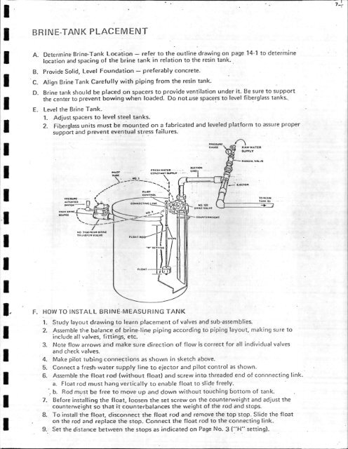
BRINE-TANK PLACEMENT<br />
Bo<br />
Eo<br />
Determine Brine-Tank Location refer to the outline drawing on page 14-1 to determine<br />
location and spacing of the brine tank in relation to the resin tank.<br />
Provide Solid, Level Foundation preferably concrete.<br />
Aiign Brine Tank Carefully with piping from the resin tank.<br />
Brine tank should be placed on spacers to provide ventilation under it. Be sure to support<br />
the center to prevent bowing when loaded. Do notJse space.rs to level fiberglass tanks.,<br />
Level the Brine Tank.<br />
1. Adjust spacers to level steel tanks.<br />
2. Fiberglass units must be mounted on a fabricated and leveled platform to assure proper<br />
support and prevent eventual st.re.ss failures.<br />
HOW TO INSTALL BRINE-MEASURING TANK<br />
1. Study layout drawing to learn placement of valves and sub-assemblies.<br />
2. Assemble the balance of brine-line piping according to piping layout, making sure to<br />
include all valves, fit-tings, etc.<br />
3. Note flow arrows and make sure direction of flow is correct for all individual valves<br />
and check valves.<br />
4. Make pilot tubing connections as shown in sketch above.<br />
5. Connect a fresh-water supply line to ejector and pilot control as shown.<br />
6. Assemble the float rod (without float) and screw into threaded end of connnectin 9 link.<br />
a. Float rod must hang vertically to enable float to slide freely.<br />
b. Rod must be free to move up and down without touching Iottom of tank.<br />
7. Before installing the float, loosen the set screw on the counterweight and adjust the<br />
counterweight so that it counterbalances the weight of the rod and stops.<br />
8. To install the float, disconnect the float rod and remove the top stop. Slide the float<br />
on the rod and replace the stop. Connect the float rod to the connecting link.<br />
9. Set the distance between the stops as indicated on Page No. 3 ("H’" setting).