Untitled - Senate Judiciary Committee
Untitled - Senate Judiciary Committee
Untitled - Senate Judiciary Committee

Create successful ePaper yourself
Turn your PDF publications into a flip-book with our unique Google optimized e-Paper software.
I BULLETIN<br />
I<br />
I I<br />
1<br />
I I<br />
I I<br />
I<br />
I i<br />
I<br />
I<br />
I<br />
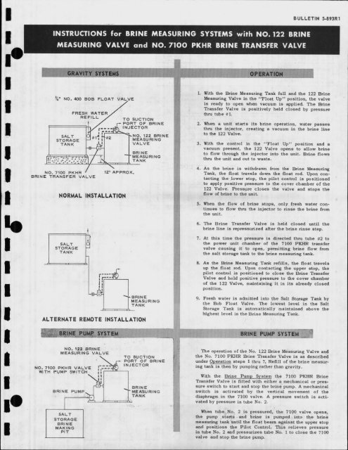
INSTRUCTIONS for BRINE MEASURING SYSTEMS with NO. 122 BRINE<br />
MEASURING VALVE and NO. 71OO PKHR BRINE TRANSFER VALVE<br />
" NO.<br />
400 BOB<br />
WATER/<br />
FLOAT VALVE<br />
FRESH<br />
REFILL / TO SUCTION<br />
/ PORT OF BRINE<br />
STORAGE<br />
TANK<br />
J MEASURING<br />
VALVE<br />
/ BRINE<br />
L,, -o; ,.’:,--r -T MEASURING<br />
.....; , o’o’,’-’;:I/ _"k TANK<br />
NO. 7100 PKHR 12" APPROX.<br />
BRINE TRANSFER VALVE<br />
NORMAL INSTALLATION<br />
STORAGE<br />
TANK<br />
ALTERNATE REMOTE INSTALLATION<br />
NO. I;2 BRINE<br />
MEASURING VALVE<br />
TO sucTION<br />
.r-- PORT OF BRINE<br />
,--. INJECTOR<br />
N O. 7 00 PKHR VALVE I-.--{<br />
WITH PUMP SWITCH il<br />
[ I BRINE<br />
BRINE PUMP MEAURING<br />
SALT<br />
STORAGE<br />
BRINE<br />
MAKING<br />
PiT<br />
5.893R1<br />
1. With the Brine Measuring Tank full and the 122 Brine<br />
Measuring Valve in the "Float Up" position, the valve<br />
is ready to open when vacuum is applied. The Brine<br />
Transfer Valve is positively held closed by pressure<br />
thru tube #1.<br />
2. When unit starts its brine operation, water passes<br />
thrd the injector, creating vacuum in the brine line<br />
to the 122 Valve.<br />
3. With the control in the ’Float Up" position and<br />
vacuum present, the 122 Valve opens to a11ow brine<br />
to flow through the injector into the unit. Brine flows<br />
thru the unit and out to waste.<br />
4. As the brine is withdrawn from the Brine Measuring<br />
Tank, the float travels down the float rod. Upon contacting<br />
the lower stop, the pilot control is positioned<br />
to apply positive pressure to the cover chamber of the<br />
122 Valve. Pressure closes the valve and stops the<br />
flow of brine to the unit.<br />
5. When the flow of brine stops, only fresh water continues<br />
to flow thru the injector to rinse the brine from<br />
the unit.<br />
6. The Brine Transfer Valve is held closed until the<br />
brine line is repressurized after the brine rinse step.<br />
7. At this time the pressure is directed thru tube #2 to<br />
the power unit chamber of the 7100 PKI-IR transfer<br />
valve causing it to open, permitting brine flow from<br />
the salt storage tank to the brine measuring tank.<br />
8. As the Brine Measuring Tank refills, the float travels<br />
up the float rod. Upon contacting the upper stop, the<br />
pilot control is positioned to close the Brine Transfer<br />
Valve and hold positive pressure to the cover chamber<br />
of the 122 Valve, maintaining it in its already closed<br />
position.<br />
9. Fresh water is admitted into the Salt Storage Tank by<br />
the Bob Float Valve. The lowest level in the Salt<br />
Storage Tank is automatically maintained above the<br />
highest level in the Brine Measuring Tank.<br />
The operation of the No. 122 Brine Measuring Valve and<br />
the No. 7100 PKHR Brine Transfer Valve is described<br />
under steps thru 7. Refill of the brine measuring<br />
tank is then by pumping rather than gravity.<br />
With the Brine Pump ’System the 7100 PKHR Brine<br />
Transfer Valve is fitted with either a mechanical or pressure<br />
switch to start and stop the brine pump. A mechanical<br />
switch is activated by the vertical movement of the<br />
diaphragm in the 7100 valve. A pressure switch is activated<br />
by pressure tube No. 2.<br />
When tube No. 2 is pressured, the 7!.00 valve opens,<br />
the pump starts, and brine is pumped into the brine<br />
measuring tank until the float bears against the upper stop<br />
and positions the Pilot Control. This relieves pressure<br />
in tube No. 2 and pressurizes tube No. to close the 7100<br />
valve and stop the brine pump.