Complete issue 30:3 as one pdf - TUG
Complete issue 30:3 as one pdf - TUG
Complete issue 30:3 as one pdf - TUG

Create successful ePaper yourself
Turn your PDF publications into a flip-book with our unique Google optimized e-Paper software.
TEX Education EUROTEX 2009 E33<br />
Appendix I: Contest Solutions<br />
PhilTaylor submitted the following mean and lean post<br />
conference solution to the Contest, b<strong>as</strong>ed on what is said<br />
on TEXbook p204. He told me that the working of # at<br />
the end of the parameter list is little understood, but very<br />
useful.<br />
Indeed, I had to look up that functionality and do the<br />
replacement to see what it does. A paradigm, though<br />
I don’t know at the moment where Knuth used it. Phil’s<br />
solution is a near solution, because curly braces are still<br />
needed around the filename.<br />
But...<br />
mean and lean it is, and I reused it already, adapted, for<br />
getting a list of all PS pictures used in this paper.<br />
I realized, and use it <strong>as</strong> an aid in remembering, that<br />
the # at the end of the parameter list is a workaround<br />
for having a curly opening brace <strong>as</strong> separator.<br />
\def \jpg #1#%<br />
{\def \next<br />
{\immediate \<strong>pdf</strong>ximage #1<br />
{\the \toks 0 .jpg}<br />
\<strong>pdf</strong>refximage \<strong>pdf</strong>l<strong>as</strong>tximage<br />
}<br />
\after<strong>as</strong>signment \next<br />
\toks 0 =<br />
}<br />
%Use<br />
\jpg width <strong>30</strong>0pt height <strong>30</strong>pt {P-Taylor}<br />
I came up with the solution below, which I will add to my<br />
FIFO paradigms list in my TEXing Paradigms collection.<br />
Of course, I used this <strong>one</strong> for my purpose.<br />
\def\jpgD#1\par{\def\scaling{}<br />
\fifow#1 \wofif %Sentinels<br />
\<strong>pdf</strong>ximage\scaling\expandafter{\fn}<br />
$$\<strong>pdf</strong>refximage\<strong>pdf</strong>l<strong>as</strong>tximage$$}<br />
%<br />
\def\fifow#1 #2{\process{#1}#2<br />
\ifx#2\wofif\expandafter\wofif\fi<br />
\fifow#2}<br />
%<br />
\def\wofif#1\wofif{}<br />
%<br />
\def\process#1#2{%<br />
\ifx#2\wofif\def\fn{#1.jpg}%<br />
\else\edef\scaling{\scaling\space#1}%<br />
\fi}<br />
Both solutions circumvent the pitfall of parsing the<br />
arguments. The height... and width... if present, are<br />
just p<strong>as</strong>sed through.<br />
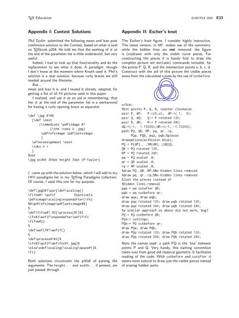
Appendix II: Escher’s knot<br />
The Escher’s knot figure, I consider highly instructive.<br />
The latest version, in MP, makes use of the symmetry,<br />
while the hidden lines are not removed: the figure<br />
is (re)drawn with only the visible curve pieces. For<br />
constructing the pieces it is handy first to draw the<br />
complete picture wit dotlabel commands included, for<br />
the points P, Q, R, and the intersection points a, b, c, d.<br />
Construct with the aid of this picture the visible pieces<br />
anew from the calculated curves by the use of cutbefore.<br />
u=5cm;<br />
%Ext points P, Q, R, counter clockwise<br />
pair P, dP; P:=(0,u); dP:=( 1, 0);<br />
pair Q, dQ; Q:= P rotated 120;<br />
pair R, dR; R:= P rotated 240;<br />
dQ:=(-1, 1.73205);dR:=(-1, -1.73205);<br />
path PQ, QR, RP, pq, qr, rp,<br />
PQa, PQb, pqa, pqb;%pieces<br />
drawoptions(withcolor blue);<br />
PQ = P{dP}.. .5R{dR}..{dQ}Q;<br />
QR = PQ rotated 120;<br />
RP = PQ rotated 240;<br />
pq = PQ scaled .8;<br />
qr = QR scaled .8;<br />
rp = RP scaled .8;<br />
%draw PQ..QR..RP;%No hidden lines removed<br />
%draw pq..qr..rp;%No hidden lines removed<br />
%Just the pieces instead of<br />
%hidden lines removal<br />
pqa = pq cutafter QR;<br />
pqb = pq cutbefore qr;<br />
draw pqa; draw pqb;<br />
draw pqa rotated 120; draw pqb rotated 120;<br />
draw pqa rotated 240; draw pqb rotated 240;<br />
%a similar approach <strong>as</strong> above did not work, bug?<br />
PQ:= PQ cutbefore QR;<br />
PQa:= cuttings;<br />
PQb:= PQ cutbefore qr;<br />
draw PQa; draw PQb;<br />
draw PQa rotated 120; draw PQb rotated 120;<br />
draw PQa rotated 240; draw PQb rotated 240;<br />
Note the names used: a path PQ is the ‘line’ between<br />
points P and Q. Very handy, this naming convention<br />
taken over from good old cl<strong>as</strong>sical geometry. It facilitates<br />
reading of the code. With cutbefore and cutafter it<br />
seems more natural to draw just the visible pieces instead<br />
of er<strong>as</strong>ing hidden parts.