
Create successful ePaper yourself
Turn your PDF publications into a flip-book with our unique Google optimized e-Paper software.
<strong>Pneumatic</strong> <strong>Swing</strong> <strong>Clamps</strong><br />
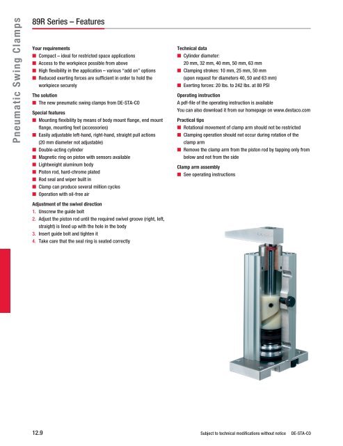
89R Series – Features<br />
Your requirements<br />
n Compact – ideal for restricted space applications<br />
n Access to the workpiece possible from above<br />
n High flexibility in the application – various “add on” options<br />
n Reduced exerting forces are sufficient in order to hold the<br />
workpiece securely<br />
The solution<br />
n The new pneumatic swing clamps from DE-STA-CO<br />
Special features<br />
n Mounting flexibility by means of body mount flange, end mount<br />
flange, mounting feet (accessories)<br />
n Easily adjustable left-hand, right-hand, straight pull actions<br />
(20 mm diameter not adjustable)<br />
n Double-acting cylinder<br />
n Magnetic ring on piston with sensors available<br />
n Lightweight aluminum body<br />
n Piston rod, hard-chrome plated<br />
n Rod seal and wiper built in<br />
n Clamp can produce several million cycles<br />
n Operation with oil-free air<br />
Adjustment of the swivel direction<br />
1. Unscrew the guide bolt<br />
2. Adjust the piston rod until the required swivel groove (right, left,<br />
straight) is lined up with the hole in the body<br />
3. Insert guide bolt and tighten it<br />
4. Take care that the seal ring is seated correctly<br />
Technical data<br />
n Cylinder diameter:<br />
20 mm, 32 mm, 40 mm, 50 mm, 63 mm<br />
n Clamping strokes: 10 mm, 25 mm, 50 mm<br />
(upon request for diameters 40, 50 and 63 mm)<br />
n Exerting forces: 20 lbs. to 242 lbs. at 80 PSI<br />
Operating instruction<br />
A pdf-file of the operating instruction is available<br />
You can also download it from our homepage on www.destaco.com<br />
Practical tips<br />
n Rotational movement of clamp arm should not be restricted<br />
n Clamping operation should not occur during rotation of the<br />
clamp arm<br />
n Remove the clamp arm from the piston rod by tapping only from<br />
below and not from the side<br />
Clamp arm assembly<br />
n See operating instructions<br />
12.9 Subject to technical modifications without notice DE-STA-CO
h8<br />
h7<br />
h6<br />
ød3<br />
l4<br />
Model no.<br />
89R20-010-1<br />
89R32-010-1<br />
89R40-010-1<br />
89R40-025-1<br />
89R50-025-1<br />
89R63-025-1<br />
ød1<br />
ød2<br />
M1<br />
S = Total stroke<br />
S1 = Travel during<br />
rotation<br />
S2 = Vertical clamp<br />
S = stroke Gesamthub<br />
S1= Schwenkhub<br />
S2= Spannhub<br />
l2<br />
l3<br />
M2 h5<br />
l1<br />
M3<br />
M3<br />
l5<br />
Total stroke<br />
S<br />
[mm]<br />
21.0<br />
28.0<br />
31.5<br />
46.5<br />
52.0<br />
58.5<br />
h4<br />
h2<br />
l6<br />
h1<br />
h3<br />
S<br />
S2 S1<br />
Schwenkbereich 90° * links<br />
Rotation range 90°<br />
Standardeinstellung<br />
werkseitig<br />
+ -5°<br />
(standard adjustment)<br />
Schwenkbereich<br />
Rotation range<br />
90° rechts + -5°<br />
right<br />
Travel during<br />
rotation<br />
S1<br />
[mm]<br />
11.0<br />
18.0<br />
21.5<br />
21.5<br />
27.0<br />
33.5<br />
Vertical clamp<br />
S2<br />
[mm]<br />
10<br />
10<br />
10<br />
25<br />
25<br />
25<br />
[lbs.]<br />
89R Series – Specifications<br />
DE-STA-CO Subject to technical modifications without notice 12.10<br />
450<br />
400<br />
350<br />
300<br />
250<br />
200<br />
150<br />
100<br />
50<br />
1.200<br />
Operating pressure<br />
min.<br />
PSI<br />
40 60<br />
Exerting force diagram<br />
max.<br />
PSI<br />
30 145<br />
Exerting force<br />
at 80 PSI<br />
20<br />
62<br />
94<br />
94<br />
154<br />
242<br />
80 100 120<br />
[PSI]<br />
Piston dia.<br />
S1<br />
[mm]<br />
20<br />
32<br />
40<br />
40<br />
50<br />
63<br />
Weight<br />
[lbs.]<br />
0.66<br />
1.32<br />
2.09<br />
2.43<br />
3.97<br />
6.17<br />
Model no. ød1 ød2 ød3 h1 h2 h3 h4 h5 h6 h7 h8 l1 l2 l3 l4 l5 l6 M1 M2 M3<br />
89R20-010-1 18 10 4.6 19.8 8 105.5 66.0 13.2 15 14 14 39.5 35.0 22 16.0 22 32 M5 M6 M5<br />
89R32-010-1 22 12 5.5 23.7 11 125.0 83.0 17.5 17 16 16 60.0 54.0 36 24.0 32 45 M6 M8 G1/8<br />
89R40-010-1 30 16 5.5 25.0 11 140.0 95.0 21.0 17 25 25 66.0 60.0 40 27.3 40 54.5 M8 M8 G1/8<br />
89R40-025-1 30 16 5.5 25.0 11 170.0 125.0 21.0 17 25 25 66.0 60.0 40 27.3 40 54.5 M8 M8 G1/8<br />
89R50-025-1 40 18 7.4 31.4 11 194.5 137.0 26.7 25 25 25 78.5 72.5 50 32.5 50 65 M10 M10 G1/8<br />
89R63-025-1 45 20 9.3 33.0 15 211.5 154.5 26.5 25 25 25 95.0 88.0 62 40.0 62 80 M10 M12 G1/4<br />
500<br />
89R63<br />
89R50<br />
89R40<br />
89R32<br />
89R20<br />
140<br />
<strong>Pneumatic</strong> <strong>Swing</strong> <strong>Clamps</strong>
<strong>Pneumatic</strong> <strong>Swing</strong> Accessories<br />
Blank Arm<br />
Product features<br />
n For attaching custom made clamp arms<br />
n 360° rotatable arm<br />
n Made of aluminum<br />
Body Mount Flange<br />
Product features<br />
n For use as a model recessed to the fixture<br />
n Variable height adjustment<br />
n Can be used with end position sensors<br />
n Made of aluminum<br />
Order no.<br />
Adaptor<br />
8MA-084-1<br />
8MA-086-1<br />
8MA-087-1<br />
8MA-087-1<br />
8MA-088-1<br />
8MA-089-1<br />
Order no.<br />
Body Mount<br />
Flange<br />
8MA-092-1<br />
8MA-094-1<br />
8MA-095-1<br />
8MA-095-1<br />
8MA-096-1<br />
8MA-097-1<br />
Use with Clamp<br />
Model no. l<br />
89R20-010-1 40<br />
89R32-010-1 50<br />
89R40-010-1 50<br />
89R40-025-1 50<br />
89R50-025-1 60<br />
89R63-025-1 65<br />
12.11 Subject to technical modifications without notice DE-STA-CO<br />
l1<br />
b<br />
h2<br />
b1<br />
h1<br />
L1<br />
L3<br />
l<br />
l1<br />
l2<br />
+_0,2 l2 h h1 M1<br />
28 16 27.8 7 15<br />
35 20 35.7 9 20<br />
38 25 40.0 12 25<br />
38 25 40.0 12 25<br />
45 30 48.4 15 30<br />
48 32 53.0 18 35<br />
L4<br />
L2<br />
D1<br />
(x4)<br />
d1<br />
b<br />
h<br />
+_0,2 b1<br />
5.5 –<br />
5.5 –<br />
5.5 14<br />
5.5 14<br />
7.0 15<br />
9.0 18<br />
Use with Clamp<br />
Model no. L1 L2 L3 L4 D1 B1 B2 H1<br />
89R20-010-1 57 55 47 24 5.5 15 – –<br />
89R32-010-1 81 75 70 40 6.6 20 12 25<br />
89R40-010-1 81 80 70 45 6.6 25 17 28<br />
89R40-025-1 81 80 70 45 6.6 25 17 28<br />
89R50-025-1 101.5 100 85.5 50 9 25 17 37<br />
89R63-025-1 122 120 104 68 11 30 20 38<br />
H1<br />
Weight<br />
[lbs./pc]<br />
0.03<br />
0.08<br />
0.11<br />
0.11<br />
0.19<br />
0.28<br />
B1<br />
B2<br />
Weight<br />
[lbs./pc]<br />
0.22<br />
0.44<br />
0.55<br />
0.55<br />
0.88<br />
1.43
Order no.<br />
Clamping Arm<br />
8JG-215-1<br />
8JG-217-1<br />
8JG-218-1<br />
8JG-218-1<br />
8JG-219-1<br />
8JG-220-1<br />
Order no.<br />
End Mount<br />
Flange<br />
8MA-061-1<br />
8MA-063-1<br />
8MA-064-1<br />
8MA-064-1<br />
8MA-065-1<br />
8MA-066-1<br />
b<br />
l2<br />
M1<br />
l<br />
l1<br />
Used with Clamp<br />
h<br />
h1<br />
Model no. l l1 l2 h h1 M1 b<br />
89R20-010-1 67 52 7 15 27.8 M6 15<br />
89R32-010-1 80 60 10 20 35.7 M8 20<br />
89R40-010-1 95 70 10 25 40.0 M8 25<br />
89R40-025-1 95 70 10 25 40.0 M8 25<br />
89R50-025-1 106 80 10 30 48.4 M8 30<br />
89R63-025-1 120 90 12 35 53.0 M10 35<br />
b h<br />
l<br />
l1<br />
l2<br />
d1<br />
d2<br />
h1<br />
b1<br />
Used with Clamp<br />
Model no. h h1 d1 d2 l<br />
89R20-010-1 10 7 11 6.6 65<br />
89R32-010-1 12 7 11 6.6 80<br />
89R40-010-1 12 7 11 6.6 100<br />
89R40-025-1 12 7 11 6.6 100<br />
89R50-025-1 15 9 15 8.5 120<br />
89R63-025-1 15 9 15 8.8 130<br />
l1<br />
+_0,2 b<br />
50 32<br />
64 50<br />
80 55<br />
80 55<br />
100 65<br />
110 80<br />
Weight<br />
[lbs./pc]<br />
0.08<br />
0.14<br />
0.28<br />
0.28<br />
0.42<br />
0.66<br />
Standard Clamp Arm<br />
Product features<br />
n For standard use<br />
n 360° rotatable arm<br />
n Spindle is an accessory part<br />
(see manual clamp accessories section for spindle<br />
option beginning page 9.1)<br />
n Made of aluminum<br />
End Mount Flange<br />
Product features<br />
n Can be mounted on bottom side and top side<br />
of clamp<br />
n Made of aluminum<br />
DE-STA-CO Subject to technical modifications without notice 12.12<br />
b1<br />
+_0,2<br />
18<br />
32<br />
40<br />
40<br />
45<br />
60<br />
Weight<br />
[lbs./pc]<br />
0.07<br />
0.20<br />
0.29<br />
0.29<br />
0.46<br />
0.66<br />
<strong>Pneumatic</strong> <strong>Swing</strong> Accessories
<strong>Pneumatic</strong> <strong>Swing</strong> Accessories<br />
Magnetic Sensors<br />
Product features<br />
n Switch groove located on 3 sides of the cylinder<br />
n Continuously adjustable by means of dovetailed groove<br />
Sensors for magnetic field workpiece control system<br />
(SME-3-LED) with integrated protective<br />
circuit and light-emitting diode (PNP output)<br />
Technical Data<br />
n Medium: magnetic field and electric current<br />
n Type of design: electrical signal transmitter for<br />
contactless position indication<br />
n Type of attachment: clamping in longitudinal keyway<br />
n Connection: 3-core cable, 2.5 m, max. 10 W/500<br />
mA/12-27 V AC/DC<br />
n Type of protection<br />
in accordance with<br />
DIN 40050: IP 66<br />
n Temperature range: fixed cable installation<br />
-20 to + 60° C<br />
moveable cable installation<br />
-5 to + 60° C<br />
n Material: housing GD-Mg, cable PVC<br />
Mounting Feet<br />
Product features<br />
n Can be mounted on bottom side or front side<br />
n Can be mounted on 4 sides of the cylinder<br />
n Made of aluminum<br />
Order no.<br />
Order no.<br />
Mounting Feet<br />
8MA-018-1<br />
8MA-020-1<br />
8MA-021-1<br />
8MA-021-1<br />
8MA-022-1<br />
8MA-023-1<br />
Magnetic<br />
Sensors<br />
SME-3-LED<br />
SME-3-LED<br />
SME-3-LED<br />
SME-3-LED<br />
SME-3-LED<br />
SME-3-LED<br />
Used with Clamp<br />
Model no. b1 l4<br />
89R20-010-1 31.0 10.5<br />
89R32-010-1 37.5 10.5<br />
89R40-010-1 42.3 10.5<br />
89R40-025-1 42.3 10.5<br />
89R50-025-1 47.5 10.5<br />
89R63-025-1 55.0 10.5<br />
Used with Clamp<br />
12.13 Subject to technical modifications without notice DE-STA-CO<br />
b<br />
b1<br />
b1<br />
l1<br />
l<br />
Weight<br />
[lbs./pc]<br />
0.09<br />
0.09<br />
0.09<br />
0.09<br />
0.09<br />
0.09<br />
Model no. h h1 d1 l l1 b b1<br />
89R20-010-1 137.5 22 7 4 16 22 35<br />
89R32-010-1 166.0 28 7 4 18 35 50<br />
89R40-010-1 181.0 28 7 5 24 40 55<br />
89R40-025-1 211.0 28 7 5 24 40 55<br />
89R50-025-1 238.5 32 9 6 24 50 67<br />
89R63-025-1 263.5 40 11 6 27 62 85<br />
d1<br />
l4<br />
h1<br />
h<br />
Weight<br />
[lbs./pc]<br />
0.08<br />
0.15<br />
0.22<br />
0.22<br />
0.33<br />
0.52