ENEPIG: Study of Suitable Palladium and Gold Thickness in ...
ENEPIG: Study of Suitable Palladium and Gold Thickness in ...
ENEPIG: Study of Suitable Palladium and Gold Thickness in ...

Create successful ePaper yourself
Turn your PDF publications into a flip-book with our unique Google optimized e-Paper software.
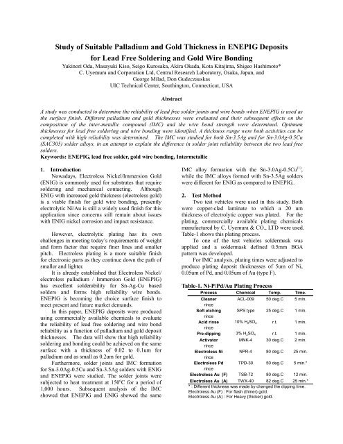
<strong>Study</strong> <strong>of</strong> <strong>Suitable</strong> <strong>Palladium</strong> <strong>and</strong> <strong>Gold</strong> <strong>Thickness</strong> <strong>in</strong> <strong>ENEPIG</strong> Deposits<br />
for Lead Free Solder<strong>in</strong>g <strong>and</strong> <strong>Gold</strong> Wire Bond<strong>in</strong>g<br />
Yuk<strong>in</strong>ori Oda, Masayuki Kiso, Seigo Kurosaka, Akira Okada, Kota Kitajima, Shigeo Hashimoto*<br />
C. Uyemura <strong>and</strong> Corporation Ltd, Central Research Laboratory, Osaka, Japan, <strong>and</strong><br />
George Milad, Don Gudeczauskas<br />
UIC Technical Center, South<strong>in</strong>gton, Connecticut, USA<br />
Abstract<br />
A study was conducted to determ<strong>in</strong>e the reliability <strong>of</strong> lead free solder jo<strong>in</strong>ts <strong>and</strong> wire bonds when <strong>ENEPIG</strong> is used as<br />
the surface f<strong>in</strong>ish. Different palladium <strong>and</strong> gold thicknesses were evaluated <strong>and</strong> their subsequent effects on the<br />
composition <strong>of</strong> the <strong>in</strong>ter-metallic compound (IMC) <strong>and</strong> the wire bond strength were determ<strong>in</strong>ed. Optimum<br />
thicknesess for lead free solder<strong>in</strong>g <strong>and</strong> wire bond<strong>in</strong>g were identified. A thickness range were both activities can be<br />
completed with high reliability was determ<strong>in</strong>ed. The IMC was studied for both Sn-3.5Ag <strong>and</strong> for Sn-3.0Ag-0.5Cu<br />
(SAC305) solder alloys, <strong>in</strong> an attempt to expla<strong>in</strong> the difference <strong>in</strong> solder jo<strong>in</strong>t reliability between the two lead free<br />
solders.<br />
Keywords: <strong>ENEPIG</strong>, lead free solder, gold wire bond<strong>in</strong>g, Intermetallic<br />
1. Introduction<br />
Nowadays, Electroless Nickel/Immersion <strong>Gold</strong><br />
(ENIG) is commonly used for substrates that require<br />
solder<strong>in</strong>g <strong>and</strong> mechanical contact<strong>in</strong>g. Although<br />
ENIG with <strong>in</strong>creased gold thickness (electroless gold)<br />
is a viable f<strong>in</strong>ish for gold wire bond<strong>in</strong>g, presently<br />
electrolytic Ni/Au is still a widely used f<strong>in</strong>ish for this<br />
application s<strong>in</strong>ce concerns still rema<strong>in</strong> about issues<br />
with ENIG nickel corrosion <strong>and</strong> impact resistance.<br />
However, electrolytic plat<strong>in</strong>g has its own<br />
challenges <strong>in</strong> meet<strong>in</strong>g today’s requirements <strong>of</strong> weight<br />
<strong>and</strong> form factor that require f<strong>in</strong>er l<strong>in</strong>es <strong>and</strong> smaller<br />
pitch. Electroless plat<strong>in</strong>g is a more suitable f<strong>in</strong>ish<br />
for electronic parts as they cont<strong>in</strong>ue down the path <strong>of</strong><br />
smaller <strong>and</strong> lighter.<br />
It is already established that Electroless Nickel/<br />
electroless palladium / Immersion <strong>Gold</strong> (<strong>ENEPIG</strong>)<br />
has excellent solderability for Sn-Ag-Cu based<br />
solders <strong>and</strong> forms high reliability wire bonds.<br />
<strong>ENEPIG</strong> is becom<strong>in</strong>g the choice surface f<strong>in</strong>ish to<br />
meet present <strong>and</strong> future market dem<strong>and</strong>s.<br />
In this paper, <strong>ENEPIG</strong> deposits were produced<br />
us<strong>in</strong>g commercially available chemicals to evaluate<br />
the reliability <strong>of</strong> lead free solder<strong>in</strong>g <strong>and</strong> wire bond<br />
reliability as a function <strong>of</strong> palladium <strong>and</strong> gold deposit<br />
thicknesses. The data will show that high reliability<br />
solder<strong>in</strong>g <strong>and</strong> bond<strong>in</strong>g could be achieved on the same<br />
surface with a thickness <strong>of</strong> 0.02 to 0.1um for<br />
palladium <strong>and</strong> as small as 0.2um for gold.<br />
Furthermore, solder jo<strong>in</strong>ts <strong>and</strong> IMC formation<br />
for Sn-3.0Ag-0.5Cu <strong>and</strong> Sn-3.5Ag solders with ENIG<br />
<strong>and</strong> <strong>ENEPIG</strong> were studied. The solder jo<strong>in</strong>ts were<br />
subjected to heat treatment at 150 o C for a period <strong>of</strong><br />
1,000 hours. Subsequent analysis <strong>of</strong> the IMC<br />
showed that <strong>ENEPIG</strong> <strong>and</strong> ENIG showed the same<br />
IMC alloy formation with the Sn-3.0Ag-0.5Cu (1) ,<br />
while the IMC alloys formed with Sn-3.5Ag solders<br />
were different for ENIG as compared to <strong>ENEPIG</strong>..<br />
2. Test Method<br />
Two test vehicles were used <strong>in</strong> this study. Both<br />
were copper-clad lam<strong>in</strong>ate to which a 20 um<br />
thickness <strong>of</strong> electrolytic copper was plated. For the<br />
plat<strong>in</strong>g, commercially available plat<strong>in</strong>g chemicals<br />
manufactured by C. Uyemura & CO., LTD were used.<br />
Table-1 shows this plat<strong>in</strong>g process.<br />
To one <strong>of</strong> the test vehicles soldermask was<br />
applied <strong>and</strong> a soldermask def<strong>in</strong>ed 0.5mm BGA<br />
pattern was developed.<br />
For IMC analysis, plat<strong>in</strong>g times were adjusted to<br />
produce plat<strong>in</strong>g deposit thicknesses <strong>of</strong> 5um <strong>of</strong> Ni,<br />
0.05um <strong>of</strong> Pd, <strong>and</strong> 0.05um <strong>of</strong> Au (type F).<br />
Table-1. Ni-P/Pd/Au Plat<strong>in</strong>g Process<br />
Process Chemical Temp. Time.<br />
Cleaner ACL-009 50 deg.C 5 m<strong>in</strong>.<br />
r<strong>in</strong>ce<br />
S<strong>of</strong>t etch<strong>in</strong>g SPS type 25 deg.C 1 m<strong>in</strong>.<br />
r<strong>in</strong>ce<br />
Acid r<strong>in</strong>se 10% H 2SO 4 r.t. 1 m<strong>in</strong>.<br />
r<strong>in</strong>ce<br />
Pre-dipp<strong>in</strong>g 3% H 2SO 4 r.t. 1 m<strong>in</strong>.<br />
Activator MNK-4 30 deg.C 2 m<strong>in</strong>.<br />
r<strong>in</strong>ce<br />
Electroless Ni NPR-4 80 deg.C 25 m<strong>in</strong>.<br />
r<strong>in</strong>ce<br />
Electroless Pd TPD-30 50 deg.C 5 m<strong>in</strong>.*<br />
r<strong>in</strong>ce<br />
Electroless Au (F) TSB-72 80 deg.C 12 m<strong>in</strong>.<br />
Electroless Au (A) TWX-40 82 deg.C 25 m<strong>in</strong>.*<br />
* : Different thickness was made by changed the dipp<strong>in</strong>g time.<br />
Electroless Au (F) : For flash (th<strong>in</strong>er) gold.<br />
Electroless Au (A) : For Heavy (thicker) gold.
For study <strong>of</strong> the effects <strong>of</strong> different Pd <strong>and</strong> Au<br />
thickness, the Ni thickness was fixed at 5um. The<br />
desired thicknesses <strong>of</strong> Pd <strong>and</strong> Au (type A) were then<br />
plated. Type A gold bath is capable <strong>of</strong> produc<strong>in</strong>g<br />
higher thicknesses <strong>of</strong> Au as compared to gold bath<br />
type F <strong>and</strong> was used for thicker gold deposits.<br />
3. Results <strong>of</strong> Solderability Test<strong>in</strong>g<br />
Table 2 is a summary <strong>of</strong> the solderabilitiy test<br />
conditions which are considered severe assembly<br />
conditions. Fig.-1 shows the results <strong>of</strong> this test<strong>in</strong>g.<br />
Table-2 Solderability Test<strong>in</strong>g Conditions<br />
Solder ball Senju Sn-3.0Ag-0.5Cu 0.6mm!<br />
Flux Senju 529D-1 RMA type<br />
Reflow <strong>in</strong>strument TAMURA TMR-15-22LH<br />
Reflow condition 5 times reflow at 260 deg.C top.<br />
Ball pull <strong>in</strong>strument Dage series 4000<br />
Ball pull speed 1000"m/sec<br />
!<br />
Pd thickness (um)<br />
Au thickness (um)<br />
0.03 0.05 0.07 0.1 0.15 0.2 0.25 0.3 0.4<br />
0 * 5 20 20 10 10 13 10 8 5<br />
0.01 90 90 90 90 90 80 80 55 60<br />
0.02 100 100 100 100 100 90 90 90 90<br />
0.03 100 100 100 100 100 100 100 100 90<br />
0.05 100 100 100 100 100 100 100 100 98<br />
0.07 100 100 100 100 100 100 98 95 90<br />
0.10 90 90 90 90 90 90 88 85 80<br />
0.12 85 85 83 85 80 80 60 73 55<br />
0.15 50 60 60 55 55 55 55 60 50<br />
0.20 50 60 50 55 58 70 30 35 30<br />
0.30 20 45 40 30 20 30 20 30 30<br />
Fig.-1 Results <strong>of</strong> Solderability Test<strong>in</strong>g<br />
Values <strong>in</strong> Fig.-1 show a score for fracture mode<br />
after the completion <strong>of</strong> solder ball pull test<strong>in</strong>g.<br />
Po<strong>in</strong>ts were assigned to 3 types <strong>of</strong> fracture modes.<br />
For a complete fracture <strong>in</strong> the solder ball, 5 po<strong>in</strong>ts<br />
were assigned. If the fracture <strong>in</strong>terface showed 25% IMC at the fracture<br />
surface was assigned zero po<strong>in</strong>ts. For each test<br />
condition 20 balls were pulled <strong>and</strong> the 20 fracture<br />
surface were exam<strong>in</strong>ed <strong>and</strong> assigned values as above.<br />
For example; if all 20 balls fractured completely <strong>in</strong><br />
the solder with no IMC show<strong>in</strong>g, each would be<br />
assigned 5 po<strong>in</strong>ts for a total score <strong>of</strong> 100.<br />
The calculation result <strong>in</strong>dicates that solderability<br />
(for these severe test conditions) <strong>in</strong> case <strong>of</strong> palladium<br />
deposit thickness <strong>of</strong> 0 um, i.e., ENIG is less robust<br />
compared to that if only a small thickness <strong>of</strong><br />
palladium is conta<strong>in</strong>ed. However, as the palladium<br />
deposit thickness <strong>in</strong>creases, it beg<strong>in</strong>s to show adverse<br />
effects on the fracture mode.<br />
On the other h<strong>and</strong> <strong>in</strong>creases <strong>in</strong> the gold deposit<br />
thickness (deposits up to 0.4um) do not show a<br />
similar degradation on fracture mode. If solder jo<strong>in</strong>t<br />
reliability is the only consideration, a palladium<br />
deposit thickness <strong>of</strong> approximately 0.02 to 0.1 um<br />
<strong>and</strong> gold deposit thickness <strong>of</strong> approximately 0.05um<br />
are more than adequate to achieve high reliability<br />
solder jo<strong>in</strong>ts.<br />
4. <strong>Gold</strong> <strong>and</strong> <strong>Palladium</strong> Deposit <strong>Thickness</strong> <strong>and</strong><br />
Wire Bondability<br />
In a previous paper, it was reported that <strong>ENEPIG</strong><br />
deposits, when exposed to heat treatment could still<br />
prevent the diffusion <strong>of</strong> the underly<strong>in</strong>g nickel, even <strong>in</strong><br />
areas where the palladium deposit is extremely th<strong>in</strong> (2) .<br />
Nickel diffusion to the gold surface is a major<br />
contributor to loss <strong>of</strong> bond strength.<br />
The same test samples as those used for the<br />
solderability test<strong>in</strong>g shown <strong>in</strong> Fig.-1 were used. Heat<br />
treatment at a temperature <strong>of</strong> 175#C for a period <strong>of</strong><br />
16 hours was completed before conduct<strong>in</strong>g the wire<br />
bond<strong>in</strong>g test<strong>in</strong>g under the conditions shown <strong>in</strong><br />
Table-3.<br />
Table-3 Wire Bond<strong>in</strong>g Test<strong>in</strong>g Conditions<br />
Wire 1mil-<strong>Gold</strong><br />
Capillary B1014-51-18-12 (PECO)<br />
Wire bonder TPT HB16<br />
Stage temperature 150 deg.C<br />
Ultra sonic 250mW(1st), 250mW(2nd)<br />
Bond<strong>in</strong>g time 200msec(1st), 50msec(2nd)<br />
Load<strong>in</strong>g force 25g(1st), 50g(2nd)<br />
Step 0.7mm (1st to 2nd wire length)<br />
Wire pull <strong>in</strong>strument Dage series 4000<br />
Wire pull speed 170"m/sec<br />
Fig.-2 shows the results <strong>of</strong> gold wire bond pull<br />
test<strong>in</strong>g. The pull test data is the result <strong>of</strong> pull<strong>in</strong>g 20<br />
wires per each condition. Values shown <strong>in</strong> Fig.-2<br />
are the average value <strong>of</strong> fracture strength obta<strong>in</strong>ed by<br />
the pull test.<br />
As the results show at a palladium deposit<br />
thickness <strong>of</strong> 0um, i.e. no palladium, a gold deposit<br />
thickness > 0.3um is required to obta<strong>in</strong> good wire<br />
bond values. In contrast, the wire bond strength for<br />
<strong>ENEPIG</strong> was higher, even <strong>in</strong> areas with very low<br />
palladium deposit thickness. Further <strong>in</strong>crease <strong>in</strong><br />
palladium thickness did not improve the wire bond<br />
strength.<br />
Pd thickness (um)<br />
Au thickness (um)<br />
0.03 0.05 0.07 0.1 0.15 0.2 0.25 0.3 0.4<br />
0 * ** 4.3 4.4 3.9 3.8 3.7 5.1 8.6 9.1<br />
0.01 6.8 7.9 7.9 8.1 8.7 8.6 9.6 10.6 10.5<br />
0.02 6.7 7.9 8.6 8.2 8.5 9.0 9.5 10.2 10.7<br />
0.03 6.0 7.7 8.4 8.2 8.2 9.3 9.3 10.7 10.4<br />
0.05 6.8 7.6 8.9 8.1 8.2 9.1 9.3 10.1 10.6<br />
0.07 7.0 7.8 8.1 8.3 8.8 9.5 9.1 10.9 11.1<br />
0.10 6.0 6.7 8.1 8.3 8.4 9.3 9.2 10.0 10.8<br />
0.12 7.2 8.4 8.9 8.8 8.9 9.5 9.6 10.9 10.5<br />
0.15 6.5 8.5 8.6 8.0 9.1 9.4 10.2 10.3 10.7<br />
0.20 6.0 8.8 8.9 8.7 9.1 9.4 10.0 10.3 10.5<br />
0.30 6.6 8.8 8.5 8.3 9.0 9.6 10.0 10.2 10.6<br />
Fig.-2 Results <strong>of</strong> Wire Bond<strong>in</strong>g Test<strong>in</strong>g!<br />
However, <strong>in</strong>creas<strong>in</strong>g the thickness <strong>of</strong> the gold<br />
deposit showed a marked improvement <strong>in</strong> wire bond<br />
strength. The palladium deposit thickness was fixed<br />
at 0.05um to check the effect <strong>of</strong> gold deposit<br />
thicknesses <strong>of</strong> 0.05um <strong>and</strong> 0.3um, respectively.<br />
!
Po<strong>in</strong>ts with 6.5g wire pull strength <strong>in</strong> the gold deposit<br />
thickness <strong>of</strong> 0.05um <strong>and</strong> those with 11.5g strength <strong>in</strong><br />
the gold deposit thickness <strong>of</strong> 0.3um were chosen, to<br />
conduct SEM observations on the secondary bond<br />
surface after the wire was pulled. Fig.-3 shows the<br />
results <strong>of</strong> these observations. Observation on the<br />
fracture surface <strong>in</strong>dicated a wide difference<br />
A u = 0.05"m<br />
A u =0.30"m<br />
Fig.-3 Difference <strong>in</strong> shape between secondary<br />
wire bond when mak<strong>in</strong>g change to gold deposit<br />
thickness<br />
between the 2 gold thicknesses tested. Exposed<br />
underly<strong>in</strong>g metal was evident <strong>in</strong> the case <strong>of</strong> the<br />
0.05um gold thickness. In contrast with the 0.3um<br />
gold thickness no exposed underly<strong>in</strong>g metal was<br />
evident.<br />
S<strong>in</strong>ce gold is a s<strong>of</strong>t metal, it can be theorized<br />
that unless the gold deposit has a certa<strong>in</strong> level <strong>of</strong><br />
thickness for wire bond<strong>in</strong>g, the underly<strong>in</strong>g metal is<br />
scraped <strong>of</strong>f to degrade the pull strength. The thicker<br />
gold deposit has a cushion<strong>in</strong>g effect on the bond <strong>and</strong><br />
produces a bond <strong>of</strong> superior strength. Insufficient<br />
gold <strong>and</strong> the possibility <strong>of</strong> nickel diffusion are the<br />
ma<strong>in</strong> contributors to the loss <strong>of</strong> wire bond strength.<br />
5. Analyses <strong>of</strong> IMC Alloy Layers<br />
As can be judged even from Fig.-1, the solder jo<strong>in</strong>t<br />
formed with <strong>ENEPIG</strong> ma<strong>in</strong>ta<strong>in</strong>s a high degree <strong>of</strong><br />
reliability under strict reflow conditions compared to<br />
that <strong>of</strong> ENIG. Consequently, reflow was conducted at<br />
a temperature <strong>of</strong> 240 o C as plated, <strong>and</strong> samples were<br />
also aged at 150 o C for a period <strong>of</strong> 1,000 hours to<br />
simulate long-term reliability test<strong>in</strong>g. In the<br />
previous paper, reliability evaluations were made on<br />
solder jo<strong>in</strong>ts us<strong>in</strong>g Sn-3.0Ag-0.5Cu <strong>and</strong> Sn-37Pb<br />
solders (2) . In this paper, however, we made<br />
evaluations on solder jo<strong>in</strong>t reliabilities us<strong>in</strong>g<br />
Sn-3.5Ag solder <strong>and</strong> showed the results <strong>in</strong> Fig- 4.<br />
<strong>ENEPIG</strong> showed degradation <strong>in</strong> strength <strong>and</strong> fracture<br />
mode as heat treatment time elapses when us<strong>in</strong>g<br />
Sn-3.5Ag solder, which was the same as that shown<br />
when us<strong>in</strong>g Sn-37Pb solder. In addition, like the<br />
previous paper, EPMA analysis was done <strong>of</strong> the<br />
distribution <strong>of</strong> each element at bonded <strong>in</strong>terfaces after<br />
1,000 hours <strong>of</strong> heat treatment at a temperature <strong>of</strong><br />
150 o C. It turned out as shown <strong>in</strong> Fig.-5, that<br />
Sn-3.5Ag solder showed the same palladium<br />
aggregates that were observed with Sn-37Pb solder.<br />
In contrast when Sn-3.0Ag-0.5Cu is soldered to an<br />
<strong>ENEPIG</strong> deposit, the palladium at the IMC is<br />
uniformly distributed with no signs <strong>of</strong> aggregates.<br />
This absence <strong>of</strong> palladium aggregates with SAC<br />
solder is a possible reason why the solder jo<strong>in</strong>t<br />
reliability is higher than either Sn-37Pb or Sn-3.5Ag,<br />
under the conditions <strong>of</strong> test<strong>in</strong>g.<br />
The details <strong>of</strong> the IMC layers for Sn-3.0Ag-0.5Cu<br />
<strong>and</strong> Sn-3.5Ag were analyzed by TEM. Fig.-6 shows<br />
TEM image <strong>in</strong> the vic<strong>in</strong>ity <strong>of</strong> IMC layers with<br />
Sn-3.0Ag-0.5Cu soldered to the <strong>ENEPIG</strong> deposit<br />
after apply<strong>in</strong>g heat treatment at a temperature <strong>of</strong><br />
150 o C for a period <strong>of</strong> 1,000 hours, <strong>and</strong> Fig. 7 shows<br />
the result <strong>of</strong> EDS analysis <strong>of</strong> the spots shown <strong>in</strong> the<br />
micrograph. Accord<strong>in</strong>g to the results <strong>of</strong> EDS<br />
measurement <strong>and</strong> diffraction measurement, Spot 3 is<br />
a layer referred to as the “phosphorous-rich layer”<br />
<strong>and</strong> assigned Ni3P$Ni. Spot 5 was assigned<br />
Ni-Sn-P s<strong>in</strong>ce Ni, Sn <strong>and</strong> P were detected <strong>and</strong> no<br />
crystals were def<strong>in</strong>ed by diffraction (3) . The Spots 6<br />
<strong>and</strong> 7 had the same hexagonal crystal as that <strong>of</strong><br />
Cu6Sn5 from the results <strong>of</strong> TEM diffraction<br />
measurement. In addition, s<strong>in</strong>ce the EDS<br />
measurement result showed the detection <strong>of</strong> Ni, these<br />
spots were identified as (Cu, Ni)6Sn5. Furthermore,<br />
s<strong>in</strong>ce this layer had uniform palladium distribution,<br />
the Spots were assigned as (Cu, Ni)6Sn5$Pd.<br />
Subsequently, Sn-3.5Ag was soldered to the <strong>ENEPIG</strong><br />
deposit, <strong>and</strong> we then conducted TEM <strong>and</strong> FE-SEM<br />
measurement <strong>of</strong> the IMC layers formed after ag<strong>in</strong>g at<br />
a temperature <strong>of</strong> 150 0 C for a period <strong>of</strong> 1000 hours.<br />
The results are shown <strong>in</strong> Fig.-8.
Pull Strength (g)<br />
Failure Mode (%)<br />
2000<br />
1500<br />
1000<br />
500<br />
0<br />
100%<br />
80%<br />
60%<br />
40%<br />
20%<br />
0%<br />
0 100 300 500 1000 0 100 300 500 1000<br />
ENIG <strong>ENEPIG</strong><br />
A : Solder B : Inter metallic (Less than 25% area) D : Inter metallic (Most all area)<br />
Fig.-4 Results <strong>of</strong> Sn-3.5Ag Solderability Test<strong>in</strong>g (Long-term heat treatment test<strong>in</strong>g at a temperature <strong>of</strong><br />
150#C)<br />
Fig.-5 Distribution <strong>of</strong> each element at bonded <strong>in</strong>terfaces after heat treatment at a temperature <strong>of</strong> 150#C<br />
for a period <strong>of</strong> 1,000 hours, after mount<strong>in</strong>g Sn-3.5Ag solder balls to <strong>ENEPIG</strong> deposit!
S p o t 6<br />
% -(C u ,N i) 6 S n 5 + P d<br />
N i-S n -P<br />
N i 3 P + N i<br />
S p o t 5<br />
Fig.-6 TEM observation on IMC with<br />
Sn-3.0Ag-0.5Cu soldered to <strong>ENEPIG</strong> deposit<br />
after heat treatment applied at a temperature <strong>of</strong><br />
150 degree C for a period <strong>of</strong> 1,000 hours<br />
!<br />
Quantitative analysis result (EDS) ; at%<br />
Spot P Ni Cu Pd Sn<br />
3 28.7 68.7 0.4 0.0 2.1<br />
5 18.0 64.2 0.1 0.0 16.8<br />
6 0.0 18.9 33.2 0.6 47.3<br />
7 0.1 17.2 35.1 1.1 46.4<br />
Fig.-7 Results <strong>of</strong> EDS <strong>of</strong> TEM Image <strong>in</strong> Fig.-6<br />
Apply<strong>in</strong>g long-term heat treatment under these<br />
conditions, two layers were found one was columnar<br />
<strong>and</strong> the other was <strong>of</strong> uniform crystal structure. The<br />
results <strong>of</strong> EPMA mapp<strong>in</strong>g (Fig. 5) show that the<br />
palladium aggregates were found only <strong>in</strong> the columnar<br />
alloy layer.<br />
Further analyses were conducted on IMC Layer<br />
Spots 7 to 9 <strong>in</strong> the lower ma<strong>in</strong> part, the results <strong>of</strong> the<br />
EDS analysis shown <strong>in</strong> Fig. 9. Furthermore, from the<br />
diffraction results, we determ<strong>in</strong>ed that the Spot 7 was<br />
Ni-Sn-P layer, <strong>and</strong> the Spots 8 <strong>and</strong> 9 were Ni3Sn4<br />
layers.<br />
Subsequently, the diffraction result <strong>in</strong>dicates that<br />
columnar parts (Spots 1 to 5) <strong>of</strong> the upper layer are <strong>of</strong><br />
structure close to Ni3Sn4, while the EDS result<br />
<strong>in</strong>dicates a ratio obviously different from that <strong>of</strong> Ni3Sn4.<br />
These ratio differences were observed with thick (3) gold<br />
deposits where an alloy (Au, Ni)Sn4 was identified.<br />
S<strong>in</strong>ce AuSn4 <strong>and</strong> PdSn4 produce the same<br />
orthorhombic crystal <strong>and</strong> due to the element ratio <strong>of</strong><br />
EDS, we determ<strong>in</strong>ed this alloy as (Pd, Ni)Sn4. This<br />
(Pd,Ni)Sn4 alloy has portions that vary <strong>in</strong> palladium<br />
content.<br />
The EPMA measurement <strong>in</strong> Fig. 5 showed the<br />
distribution <strong>of</strong> the palladium deposit thickness <strong>in</strong> alloy<br />
layers.<br />
!<br />
Additional observations on the cross section <strong>of</strong> alloy<br />
layers with vary<strong>in</strong>g palladium thicknesses were<br />
conducted. The reflow process was conducted once at a<br />
temperature <strong>of</strong> 240 o C <strong>and</strong> gave the results showed <strong>in</strong><br />
Fig. 10. The results <strong>in</strong>dicate that ENIG (Pd&0.00um)<br />
has formed needle-like alloy layers <strong>and</strong> <strong>ENEPIG</strong> has<br />
formed uniform alloy layers. However, if the palladium<br />
deposit thickness is <strong>in</strong>creased to 0.08um or higher , the<br />
alloy layers become markedly thicker. The <strong>in</strong>creased<br />
thickness has an adverse effect on the reliability <strong>of</strong> the<br />
solder jo<strong>in</strong>t.<br />
6. Conclusion<br />
TEM analysis was conducted on test pieces that were<br />
aged at a temperature <strong>of</strong> 150 o C for a period <strong>of</strong> 1,000<br />
hours after solder<strong>in</strong>g Sn-3.0Ag-0.5Cu <strong>and</strong> Sn-3.5Ag to<br />
<strong>ENEPIG</strong> deposits. For Sn-3.0Ag-0.5Cu solder, an alloy<br />
layer (Cu,Ni)6Sn5 with even palladium distribution was<br />
identified as the ma<strong>in</strong> layer. On the other h<strong>and</strong>,<br />
Sn-3.5Ag solder, revealed a dist<strong>in</strong>ct columnar alloy<br />
layer (Pd, Ni)Sn4 on the uniform alloy layer Ni3Sn4.<br />
Consequently, it is believed that the presence <strong>of</strong> the<br />
alloy layer (Pd, Ni)Sn4 adversely affects solder jo<strong>in</strong>t<br />
reliability. In addition, it was found that solder jo<strong>in</strong>t<br />
reliability was more dependent on palladium deposit<br />
thickness than gold deposit thickness, <strong>and</strong> thereby it<br />
was essential to control the palladium deposit<br />
thickness.<br />
On the other h<strong>and</strong>, with regard to wire bond<strong>in</strong>g, it is<br />
<strong>in</strong>dicated that the <strong>ENEPIG</strong> deposit makes it possible to<br />
control nickel diffusion to the deposit surface (2) . In<br />
this paper, the palladium deposit <strong>and</strong> the gold deposit<br />
thickness were varied, to determ<strong>in</strong>e their role on wire<br />
bond strength. As a result, it was found that <strong>in</strong>creased<br />
gold thickness has a cushion<strong>in</strong>g effect <strong>and</strong> is more<br />
effective <strong>in</strong> enhanc<strong>in</strong>g the wire bond strength as<br />
compared to <strong>in</strong>creas<strong>in</strong>g the palladium thickness.<br />
Summ<strong>in</strong>g up the study, solderability requires proper<br />
palladium deposit thickness, while thicker gold deposit<br />
is more advantageous for wire bondability. Increas<strong>in</strong>g<br />
the gold thickness does not improve solder jo<strong>in</strong>t<br />
reliability, nor does <strong>in</strong>creas<strong>in</strong>g the palladium thickness<br />
improve wire bondability. Consequently, it was proved<br />
that controll<strong>in</strong>g the palladium deposit thickness <strong>and</strong> the<br />
gold deposit thickness could be balanced to give high<br />
reliability for both solder<strong>in</strong>g <strong>and</strong> wire bond<strong>in</strong>g.<br />
In recent years, electroless plat<strong>in</strong>g due to <strong>in</strong>creas<strong>in</strong>g<br />
reduction <strong>in</strong> weight <strong>and</strong> size <strong>of</strong> electronic parts has<br />
been gett<strong>in</strong>g attention <strong>in</strong> addition to lead-free solder<strong>in</strong>g<br />
materials. With a good underst<strong>and</strong><strong>in</strong>g <strong>of</strong> how the<br />
<strong>ENEPIG</strong> f<strong>in</strong>ish <strong>in</strong>teracts with different lead free solders,<br />
<strong>ENEPIG</strong> can be the choice electroless alternative for<br />
today’s challeng<strong>in</strong>g electronic dem<strong>and</strong>s.
!<br />
Spot 2<br />
Spot 9<br />
(Pd,Ni)Sn 4<br />
Ni 3 P+Ni<br />
Ni 3 Sn 4<br />
Ni-Sn-P<br />
Spot 5<br />
Fig.-8 TEM <strong>and</strong> FE-SEM observations on IMC<br />
with Sn-3.5Ag soldered to <strong>ENEPIG</strong> deposit after<br />
heat treatment applied at a temperature <strong>of</strong> 150#C<br />
for a period <strong>of</strong> 1,000 hours<br />
Quantitative analysis result (EDS) ; at %<br />
Spot P Ni Pd Sn<br />
2 0.0 17.9 3.7 78.4<br />
5 0.2 19.1 0.7 79.9<br />
7 10.8 66.0 0.0 23.2<br />
8 0.2 44.7 0.0 55.1<br />
9 0.3 43.4 0.0 56.2<br />
Fig.-9 Results <strong>of</strong> EDS <strong>of</strong> TEM Image <strong>in</strong> Fig.-8<br />
Bibliography<br />
[1] Chi-Won Hwang, Katsusaki Suganuma.<br />
J.Mater. Res., 18, 2540, Nov (2003)<br />
[2] Donald Gudeczauskas et al, 39 th International<br />
Symposium on Microelectronics, October<br />
8-12, 2006, San Diego<br />
[3] V.Vuor<strong>in</strong>en, T.Laurila, H.Yu, <strong>and</strong> J.K.Kivilahti.<br />
J.appl.Phys.99, 023530 (2006)
!<br />
!<br />
Pd=0.00"m Pd=0.02"m Pd=0.04"m<br />
Pd=0.06"m Pd=0.08"m Pd=0.10"m<br />
Fig.-10 Photograph <strong>of</strong> alloy layer after conducted the reflow process once at a temperature <strong>of</strong> 240#C on<br />
Ni-P/Pd/Au deposit with changed palladium deposit thickness