Study of the ENEPIG IMC for Eutectic and LF Solders - Uyemura ...
Study of the ENEPIG IMC for Eutectic and LF Solders - Uyemura ...
Study of the ENEPIG IMC for Eutectic and LF Solders - Uyemura ...

Create successful ePaper yourself
Turn your PDF publications into a flip-book with our unique Google optimized e-Paper software.
A STUDY OF THE <strong>ENEPIG</strong> <strong>IMC</strong> FOR EUTECTIC AND <strong>LF</strong> SOLDERS<br />
G.Milad, D.Gudeczauskas, G.Obrien, A.Gruenwald<br />
<strong>Uyemura</strong> International Corporation<br />
Southington, CT<br />
ABSTRACT:<br />
The solder joint <strong>for</strong>med on an <strong>ENEPIG</strong> surface with 4<br />
different pastes namely eutectic Sn/Pb solder, copper<br />
doped Sn/Pb solder, SAC 305 <strong>and</strong> Sn/Ag were analyzed<br />
after <strong>the</strong>rmal stress ageing. The nature <strong>of</strong> <strong>the</strong> <strong>IMC</strong> <strong>and</strong> its<br />
propagation were examined by SEM in cross section as<br />
well as top down view. The top down view was obtained<br />
by stripping <strong>the</strong> reflowed paste, so that <strong>the</strong> examination <strong>of</strong><br />
variability in <strong>the</strong> <strong>IMC</strong> surface can be conducted.<br />
The study shows that <strong>the</strong> SAC 305 <strong>and</strong> copper doped<br />
(1%) Sn/Pb make a very robust solder joint on <strong>the</strong><br />
<strong>ENEPIG</strong> surface, when compared with eutectic Sn/Pb or<br />
Sn/Ag solder. The <strong>IMC</strong> is limited in thickness <strong>and</strong> more<br />
important limited in its propagation under extended<br />
<strong>the</strong>rmal stress conditioning (500 hours at 150 o C).<br />
EPMA analysis show that <strong>the</strong> copper is an integral part <strong>of</strong><br />
<strong>the</strong> <strong>IMC</strong> <strong>and</strong> its presence allows <strong>for</strong> <strong>the</strong> Pd to be evenly<br />
distributed in <strong>the</strong> <strong>IMC</strong>. In contrast, in <strong>the</strong> absence <strong>of</strong><br />
copper, <strong>the</strong>re are distinct clusters <strong>of</strong> Pd,Ni/Sn segregated<br />
from <strong>the</strong> Ni/Sn <strong>for</strong>ming <strong>the</strong> <strong>IMC</strong>.<br />
The effect <strong>of</strong> palladium thickness on <strong>the</strong> integrity <strong>of</strong> <strong>the</strong><br />
solder joint, when using SAC 305 solder, was also<br />
evaluated using a similar protocol. The data shows that<br />
increasing <strong>the</strong> palladium thickness will adversely impact<br />
<strong>the</strong> solder joint reliability.<br />
KEY WORDS:<br />
<strong>ENEPIG</strong>, <strong>IMC</strong>, <strong>Eutectic</strong>, <strong>LF</strong> solder<br />
INTRODUCTION:<br />
Surface finish products have been on <strong>the</strong> fast track <strong>of</strong><br />
evolution to meet <strong>the</strong> complexity <strong>of</strong> newer designs<br />
(lighter, faster, smaller) as h<strong>and</strong>held devices like i-pods,<br />
smart-phones, PDAs, digital cameras, camcorders,<br />
scanners etc. continue down <strong>the</strong> <strong>for</strong>m factor path. The<br />
new challenge is RoHS compliance <strong>and</strong> <strong>the</strong> need to have<br />
lead-free finishes <strong>and</strong> more important lead-free assembly<br />
compatible finishes.<br />
Surface finish is about connectivity. It is <strong>the</strong> surface<br />
which ei<strong>the</strong>r protects or <strong>for</strong>ms <strong>the</strong> connection from <strong>the</strong><br />
board to a device. Today <strong>the</strong>re is an impressive line up <strong>of</strong><br />
surface finish products in use as <strong>Eutectic</strong> Sn/Pb HASL<br />
replacement. The list includes: ENIG (electroless<br />
nickel/immersion gold), <strong>ENEPIG</strong> (electroless nickel/<br />
electroless palladium/immersion gold), immersion silver,<br />
immersion tin, OSP, as well as DIG (direct gold on copper).<br />
<strong>ENEPIG</strong> (Electroless Nickel/Electroless Palladium/Immersion<br />
Gold) is <strong>for</strong>med by <strong>the</strong> deposition <strong>of</strong> electroless Ni (120 240<br />
ins) followed by 2 6 ins <strong>of</strong> electroless Pd with an<br />
immersion gold flash (1 2 ins). <strong>ENEPIG</strong> is a good<br />
soldering surface, a gold wire bondable surface, aluminum<br />
wire bondable surface, as well as a contacting surface.<br />
Studies [1],[2] conducted to evaluate <strong>the</strong> reliability <strong>of</strong> <strong>the</strong><br />
solder joint <strong>for</strong>med on an <strong>ENEPIG</strong> surface finish with <strong>LF</strong><br />
solder <strong>and</strong> <strong>LF</strong> assembly conditions, were very eye opening.<br />
Under <strong>the</strong> <strong>the</strong>rmal stress conditions used in <strong>the</strong> study, <strong>the</strong> data<br />
showed that <strong>ENEPIG</strong> was unique in <strong>the</strong> fact that it <strong>for</strong>med a<br />
robust, higher strength solder joint with <strong>LF</strong> SAC 305 alloy, as<br />
compared to <strong>the</strong> solder joint <strong>for</strong>med with eutectic Sn/Pb<br />
solder.<br />
In this study 1% copper doped Sn/Pb was added in an ef<strong>for</strong>t to<br />
explain why SAC 305 was superior to both Sn Ag <strong>and</strong> eutectic<br />
SnPb.<br />
TEST PROTOCOL:<br />
The test vehicle was a double sided 0.062 FR-4 board. The<br />
board was copper plated, using commercially available acid<br />
copper <strong>and</strong> patterned see figures 1 <strong>and</strong> 2 . Solder mask was<br />
applied. The boards were <strong>the</strong>n plated with <strong>ENEPIG</strong> surface<br />
finish. For this study <strong>the</strong> BGA pads were screened with <strong>the</strong><br />
respective solder paste <strong>and</strong> reflowed.<br />
Table 1 shows <strong>the</strong> process sequence, that <strong>the</strong> boards were<br />
subjected to, <strong>for</strong> <strong>the</strong> application <strong>of</strong> <strong>the</strong> <strong>ENEPIG</strong> surface finish.<br />
All chemicals used were commercially available products.<br />
Under <strong>the</strong> <strong>the</strong>rmal stress conditions used in <strong>the</strong> study, <strong>the</strong> data<br />
showed that <strong>ENEPIG</strong> was unique in <strong>the</strong> fact that it <strong>for</strong>med a<br />
robust, higher strength solder joint with <strong>LF</strong> SAC 305 alloy, as<br />
compared to <strong>the</strong> solder joint <strong>for</strong>med with eutectic Sn/Pb<br />
solder.
In this study 1% copper doped Sn/Pb was added in an<br />
ef<strong>for</strong>t to explain why SAC 305 was superior to both Sn<br />
Ag <strong>and</strong> eutectic SnPb.<br />
Fig 1: Top side <strong>of</strong> <strong>the</strong> Test Vehicle with <strong>the</strong> BGA pattern<br />
used in <strong>the</strong> center top<br />
Calibration: FP (fundamental parameters) used to create <strong>the</strong><br />
calibration file with a verification using <strong>the</strong> following NIST<br />
traceable st<strong>and</strong>ards:<br />
#1: 0.8µ Au/4µPd/100µNi<br />
#2: 4µAu/15µPd/250µNi<br />
Table 1: Process Sequence<br />
(Panels were dried using a horizontal conveyorized dryer).<br />
Process step Product Temp<br />
C<br />
Time<br />
min<br />
Soak Clean ACL-007 50 5<br />
Rinse Ambient 1<br />
Acid Dip 5% Sulfuric Ambient 1<br />
Rinse Ambient 1<br />
Micro-etch SPS Ambient 1<br />
Rinse Ambient 1<br />
Pre-dip 5% Sulfuric Ambient 1<br />
Catalyst MNK-4 30 2<br />
Rinse Ambient 1<br />
Eless Ni NPR-4 80 25<br />
D/O Rinse Ambient 1<br />
Rinse DI water Ambient 1<br />
Eless Pd Talon 2.0 65 12<br />
D/O Rinse Ambient 1<br />
Rinse DI Water Ambient 1<br />
Im Gold TAM-55 80 10<br />
D/O Rinse Ambient 1<br />
Rinse DI Water Ambient 1<br />
The average thickness values <strong>for</strong> Ni, Pd <strong>and</strong> Au obtained were<br />
as follows:<br />
Nickel: 171 ins SD 11.1<br />
Palladium: 7.2 ins SD 0.81<br />
Gold: 1.2 ins SD 0.09<br />
Solder details: All solder was Type 3, no clean flux ROL0<br />
· SnPb: Indium Corp (mp 183 o C)<br />
· SnPbCu: Indium Corp Cu doped at 1%, (mp 187 o C)<br />
· SAC 305: Indium Corp (mp 217 o C)<br />
· SnAg 3.5: Alpha Metals (mp 212 o C)<br />
Fig 2: Close up <strong>of</strong> <strong>the</strong> BGA pattern used with details <strong>of</strong><br />
pad sizes<br />
The thickness <strong>of</strong> <strong>the</strong> deposited layers were verified using<br />
XRF measurements as specified below:<br />
Pin diode XRF: ThermoNoran Micron X<br />
Collimator used 20 mils in diameter<br />
Measurement time 3 minutes per pad<br />
The solder paste was screened on <strong>the</strong> BGA pads <strong>and</strong> reflowed<br />
under <strong>the</strong> following conditions:<br />
· SnPb <strong>and</strong> Cu doped SnPb solder, were reflowed at<br />
225 o C, with 60 seconds above liquidus<br />
· <strong>LF</strong> SAC 305 <strong>and</strong> SnAg (3.5) were reflowed at 247 o C<br />
with 70 seconds above liquidus.<br />
The samples were <strong>the</strong>n cross section to examine <strong>the</strong> <strong>IMC</strong> as<br />
<strong>for</strong>med. The parts were <strong>the</strong>n subjected to <strong>the</strong>rmal
Sn/Pb <strong>IMC</strong> as <strong>for</strong>med No Bake<br />
Sn/Pb <strong>IMC</strong> after 500 hours bake at 150 o C<br />
Top view after solder strip<br />
Figure 3 Sn/Pb be<strong>for</strong>e <strong>and</strong> after bake
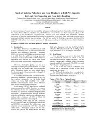
Sn/Pb/Cu <strong>IMC</strong> as <strong>for</strong>med No Bake<br />
Sn/Pb/Cu <strong>IMC</strong> after 500 Hr bake at 150 o C<br />
Top view after solder strip<br />
Figure 4 Sn/Pb/Cu be<strong>for</strong>e <strong>and</strong> after bake
Sn/Ag <strong>IMC</strong> as <strong>for</strong>med No Bake<br />
Sn/Ag <strong>IMC</strong> after 500 Hours bake at 150 o C<br />
Figure 5 Sn/Ag (3.5) be<strong>for</strong>e <strong>and</strong> after bake
SAC 305 <strong>IMC</strong> as <strong>for</strong>med No bake<br />
SAC 305 <strong>IMC</strong> as <strong>for</strong>med No bake<br />
Top view after solder strip<br />
Figure 6 SAC 305 be<strong>for</strong>e <strong>and</strong> after bake
conditioning/baking <strong>for</strong> an extended duration. Cross<br />
sections were taken <strong>and</strong> <strong>the</strong> <strong>IMC</strong> was examined after <strong>the</strong><br />
<strong>the</strong>rmal bake/conditioning.<br />
The parts were conditioned in a Precision isotemp oven<br />
<strong>for</strong> 500 hours at 150 o C. A 36 gauge welded tip K type<br />
<strong>the</strong>rmocouple was soldered to a pad on a PCB <strong>of</strong> similar<br />
size that was also a 2 layer. The temperature recorded in<br />
<strong>the</strong> solder joint controlled <strong>the</strong> conditioning temperature<br />
ra<strong>the</strong>r than <strong>the</strong> oven set point. The temperature was<br />
controlled to +/- 2 o C. The oven was returned to room<br />
temperature be<strong>for</strong>e removing <strong>the</strong> samples to avoid any<br />
rapid cool down that might have a negative impact on <strong>the</strong><br />
solder structure.<br />
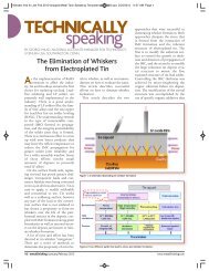
Figures 3,4,5 & 6 below show EDX elemental analysis<br />
<strong>and</strong> SEM at 5000X <strong>for</strong> <strong>the</strong> 4 types <strong>of</strong> solder be<strong>for</strong>e <strong>and</strong><br />
after heat stress. Also included are <strong>the</strong> top down views <strong>of</strong><br />
<strong>the</strong> <strong>IMC</strong> after solder stripping <strong>for</strong> <strong>Eutectic</strong> Sn/Pb, SAC<br />
305 <strong>and</strong> copper doped eutectic solder.<br />
All samples were micro-etched be<strong>for</strong>e SEM-EDX using a<br />
1% nitric acid in methanol solution.<br />
The be<strong>for</strong>e bake samples showed excellent wetting <strong>and</strong> a<br />
relatively thin <strong>IMC</strong> that was consistent with <strong>the</strong> refow<br />
time at temperature. The eutectic Sn/Pb solder exhibited a<br />
certain degree <strong>of</strong> lack <strong>of</strong> thickness uni<strong>for</strong>mity, while <strong>the</strong><br />
SAC305, Sn/Pb/Cu <strong>and</strong> SnAg exhibited a relatively even<br />
(uni<strong>for</strong>m thickness) <strong>IMC</strong>. See figures.<br />
After incubation (<strong>the</strong>rmal conditioning):<br />
· SnPb <strong>IMC</strong> grew in thickness (~5X) <strong>and</strong> was very<br />
uneven,<br />
· SnPbCu <strong>IMC</strong> show very limited propagation<br />
(~1.5 X) <strong>and</strong> was relatively even.<br />
· SAC305 <strong>IMC</strong> showed very limited propagation<br />
<strong>and</strong> was very even<br />
· SnAg <strong>IMC</strong> grew in thickness as much as <strong>the</strong><br />
eutectic Sn/Pb <strong>and</strong> was very uneven.<br />
The SnPb, SAC 305 <strong>and</strong> SnAg solders per<strong>for</strong>mance<br />
confirmed previously reported observation. What is new<br />
in this study is <strong>the</strong> observation <strong>for</strong> <strong>the</strong> SnPbCu. The data<br />
shows that copper doped eutectic solder SnPbCu behaved<br />
very similar to SAC 305 <strong>and</strong> gave a very robust solder<br />
joint <strong>for</strong>m shear strength values <strong>and</strong> limited propagation<br />
as well as evenness <strong>of</strong> <strong>the</strong> <strong>IMC</strong>.<br />
The incubated SnPb, Sn/Pb/Cu <strong>and</strong> SAC305 reflow<br />
samples were <strong>the</strong>n solder stripped <strong>and</strong> <strong>the</strong> morphology <strong>of</strong><br />
<strong>the</strong> <strong>IMC</strong> was examined. The contrast was very obvious<br />
(see figures above). There was a dramatic difference<br />
between <strong>the</strong> morphology <strong>of</strong> <strong>the</strong> <strong>IMC</strong> <strong>of</strong> <strong>the</strong> SnPb sample<br />
as compared to <strong>the</strong> copper bearing samples. The copper<br />
bearing samples showed a relatively fine grained morphology,<br />
while <strong>the</strong> SnPb was coarse grained <strong>and</strong> <strong>for</strong>med clusters.<br />
The data suggests that <strong>the</strong> copper in <strong>the</strong> solder plays a<br />
significant role in preserving <strong>the</strong> integrity <strong>of</strong> <strong>the</strong> solder joint.<br />
Previously reported EPMA analysis results showed that <strong>the</strong> Cu<br />
is concentrated in <strong>the</strong> intermetallic <strong>IMC</strong> layer <strong>and</strong> allows <strong>the</strong><br />
Pd to dissipate evenly into <strong>the</strong> <strong>IMC</strong> <strong>for</strong>ming (Cu,Ni) 6 Sn 5 +Pd.<br />
The EDX analysis in this study confirms that copper is an<br />
integral part <strong>of</strong> <strong>the</strong> <strong>IMC</strong><br />
In absence <strong>of</strong> Cu, SnPb <strong>and</strong> SnAg solders do not exhibit this<br />
homogenous <strong>IMC</strong>, but show segregated clusters <strong>of</strong><br />
(Pd,Ni) 3 Sn 4 . These clusters allow <strong>the</strong> <strong>IMC</strong> under <strong>the</strong>rmal<br />
stress to propagate <strong>and</strong> remain uneven; resulting in a weaker<br />
solder joint.<br />
Now that <strong>the</strong> study has established that copper bearing <strong>LF</strong><br />
solder makes a superior solder joint than eutectic Sn/Pb solder,<br />
<strong>the</strong> question <strong>the</strong>n becomes: is <strong>the</strong>re a thickness limit as to how<br />
much palladium can dissipate into <strong>the</strong> <strong>IMC</strong> Ano<strong>the</strong>r study<br />
was completed to determine if increasing <strong>the</strong> palladium layer<br />
thickness would have any adverse effects on <strong>the</strong> integrity <strong>of</strong><br />
<strong>the</strong> solder joint.<br />
In this study; BGA substrates were plated with palladium<br />
thickness varying from 2 uins to 12 uins, <strong>and</strong> <strong>the</strong> gold<br />
thickness was varied from 2 ins to 16 ins, while <strong>the</strong> nickel<br />
thickness remained constant at 200 ins. SAC 305 solder balls<br />
were attached to <strong>the</strong> BGA substrate. The samples were split<br />
into 2 groups. One group was conditioned using 1X <strong>LF</strong> reflow<br />
(260 o C) <strong>and</strong> <strong>the</strong> second was conditioned at 5X <strong>LF</strong> reflow. The<br />
balls were <strong>the</strong>n pulled at 2 different speeds namely 1000<br />
m/sec <strong>and</strong> at 5000 m/sec. The fracture interface was <strong>the</strong>n<br />
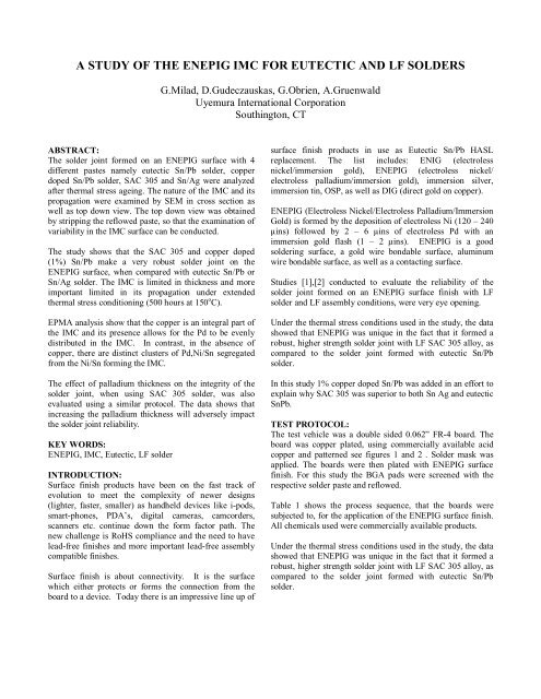
examined. The results are graphed <strong>and</strong> tabulated in Figure 7..<br />
The 1000 m/sec pull speed did not exhibit any significant<br />
difference in fracture mode; all samples fractured within <strong>the</strong><br />
solder ball. The 5000 m/sec pull speed differentiated <strong>the</strong><br />
thickness combinations as <strong>the</strong>y related to fracture mode. Two<br />
distinct fracture modes were recorded; a fracture within <strong>the</strong><br />
solder ball <strong>and</strong> an interfacial fracture that showed >50% nickel.<br />
In <strong>the</strong> higher speed pull, both <strong>the</strong> 1X reflow <strong>and</strong> <strong>the</strong> 5X reflow<br />
exhibited interfacial fractures. At 1X reflow approximately<br />
50% <strong>of</strong> <strong>the</strong> balls attached to <strong>the</strong> 12 ins thick palladium<br />
showed interfacial fractures. At 5X reflow approximately 35%<br />
<strong>of</strong> <strong>the</strong> balls attached to 8 ins palladium <strong>and</strong> ~70% <strong>of</strong> <strong>the</strong> balls<br />
attached to 12 uins <strong>of</strong> palladium showed interfacial fractures.<br />
The variation in gold thickness was not a contributor to <strong>the</strong><br />
interfacial fracture under <strong>the</strong> conditions <strong>of</strong> testing.
Figure 7 Fracture Mode <strong>for</strong> SAC305 Ball Pull results<br />
Effect <strong>of</strong> Au <strong>and</strong> Pd thickness<br />
Pull speed<br />
1,000um/sec<br />
Pull speed<br />
5,000 um/sec<br />
100%<br />
80%<br />
60%<br />
40%<br />
20%<br />
0%<br />
Au thickness 0.05 0.1 0.2 0.4 0.2 0.4 0.2 0.4 0.2 0.4 0.05 0.1 0.2 0.4 0.2 0.4 0.2 0.4 0.2 0.4<br />
Pd thickness 0.05 0.1 0.2 0.3 0.05 0.1 0.2 0.3<br />
100%<br />
80%<br />
60%<br />
40%<br />
20%<br />
Refllow X1<br />
0%<br />
Au thickness 0.05 0.1 0.2 0.4 0.2 0.4 0.2 0.4 0.2 0.4 0.05 0.1 0.2 0.4 0.2 0.4 0.2 0.4 0.2 0.4<br />
Pd thickness<br />
0.05 0.1 0.2 0.3 0.05 0.1 0.2 0.3<br />
Refllow X1<br />
Reflow conditions: Top temp. 260 deg.C<br />
Refllow X5<br />
Refllow X5<br />
A:Solder B:Ni appearance 50% D:Broken Pad<br />
The Pd thickness should be below 0.2um <strong>for</strong> optimum solder<br />
20<br />
joint reliabilities.<br />
CONCLUSION:<br />
In <strong>the</strong> first test using <strong>ENEPIG</strong> as <strong>the</strong> surface finish, it was<br />
demonstrated that <strong>the</strong> presence <strong>of</strong> copper in SAC305 plays a<br />
significant role in increasing <strong>the</strong> solder joint reliability. The<br />
copper dissipates <strong>the</strong> palladium evenly in <strong>the</strong> <strong>IMC</strong> <strong>and</strong> does<br />
not allow <strong>for</strong> excessive propagation <strong>of</strong> <strong>the</strong> <strong>IMC</strong> when<br />
conditioned at 150 o C <strong>for</strong> 500 hours. The addition or doping<br />
<strong>of</strong> eutectic SnPb solder with 1% copper demonstrated <strong>the</strong><br />
same enhanced reliability.<br />
The combination <strong>of</strong> <strong>ENEPIG</strong> with Sn/Pb eutectic solder is<br />
not recommended <strong>for</strong> high temperature use environments.<br />
In <strong>the</strong> second test SAC305 solder balls were attached to<br />
BGA substrates plated with varying thicknesses <strong>of</strong><br />
palladium <strong>and</strong> gold over a fixed nickel thickness. The<br />
samples were stressed at 1x <strong>and</strong> 5X reflow <strong>the</strong>rmal cycles.<br />
The fracture mode <strong>of</strong> <strong>the</strong> ball pull testing indicated that<br />
palladium thickness should be less than, < 8 ins <strong>for</strong><br />
maximum solder joint reliability.<br />
REFERENCES:<br />
(1) <strong>IMC</strong> Growth <strong>Study</strong> on Ni-P/Pd/Au Film <strong>and</strong> Ni-P/Au<br />
Film Using Sn/Ag/Cu Lead-Free Solder, Yukinori Oda,<br />
Masayuki Kiso, Shigeo Hashimoto, Don Gudeczauskas,<br />
IMAPS 2007<br />
(2) <strong>Study</strong> <strong>of</strong> suitable Palladium <strong>and</strong> Gold Thickness in<br />
<strong>ENEPIG</strong> film <strong>for</strong> lead free soldering <strong>and</strong> wire bonding,<br />
Yukinori Oda, Masayuki Kiso, Seigo Kurosaka, Akiro<br />
Okada, Kota Kitajima, Shiegeo Hashimoto, Don<br />
Gudeczuaskas, 41 st International Symposium<br />
Microelectronics, Providence, RI, November 2-6, 2008