ENIG with Ductile Electroless Nickel for Flex Circuit Applications
ENIG with Ductile Electroless Nickel for Flex Circuit Applications
ENIG with Ductile Electroless Nickel for Flex Circuit Applications

Create successful ePaper yourself
Turn your PDF publications into a flip-book with our unique Google optimized e-Paper software.
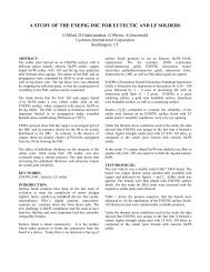
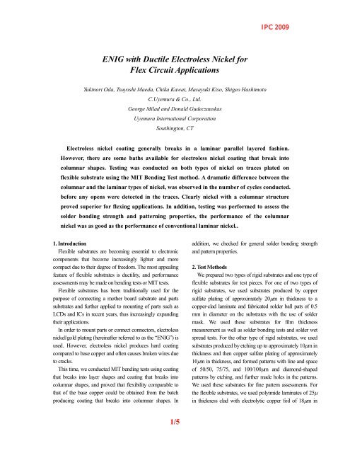
IPC 2009<strong>ENIG</strong> <strong>with</strong> <strong>Ductile</strong> <strong>Electroless</strong> <strong>Nickel</strong> <strong>for</strong><strong>Flex</strong> <strong>Circuit</strong> <strong>Applications</strong>Yukinori Oda, Tsuyoshi Maeda, Chika Kawai, Masayuki Kiso, Shigeo HashimotoC.Uyemura & Co., Ltd.George Milad and Donald GudeczauskasUyemura International CorporationSouthington, CT<strong>Electroless</strong> nickel coating generally breaks in a laminar parallel layered fashion.However, there are some baths available <strong>for</strong> electroless nickel coating that break intocolumnar shapes. Testing was conducted on both types of nickel on traces plated onflexible substrate using the MIT Bending Test method. A dramatic difference between thecolumnar and the laminar types of nickel, was observed in the number of cycles conducted.be<strong>for</strong>e any opens were detected in the traces. Clearly nickel <strong>with</strong> a columnar structureproved superior <strong>for</strong> flexing applications. In addition, testing was per<strong>for</strong>med to assess thesolder bonding strength and patterning properties, the per<strong>for</strong>mance of the columnarnickel was as good as the per<strong>for</strong>mance of conventional laminar nickel..1. Introduction<strong>Flex</strong>ible substrates are becoming essential to electroniccomponents that become increasingly lighter and morecompact due to their degree of freedom. The most appealingfeature of flexible substrates is ductility, and per<strong>for</strong>manceassessments may be made on bending tests or MIT tests.<strong>Flex</strong>ible substrates has been traditionally used <strong>for</strong> thepurpose of connecting a mother board substrate and partssubstrates and further applied to mounting of parts such asLCDs and ICs in recent years, thus increasingly expandingtheir applications.In order to mount parts or connect connectors, electrolessnickel/gold plating (hereinafter referred to as the “<strong>ENIG</strong>”) isused. However, electroless nickel produces hard coatingcompared to base copper and often causes broken wires dueto cracks.This time, we conducted MIT bending tests using coatingthat breaks into layer shapes and coating that breaks intocolumnar shapes, and proved that flexibility comparable tothat of the base copper could be obtained from the batchproducing coating that breaks into columnar shapes. Inaddition, we checked <strong>for</strong> general solder bonding strengthand pattern properties.2. Test MethodsWe prepared two types of rigid substrates and one type offlexible substrates <strong>for</strong> test pieces. For one of two types ofrigid substrates, we used substrates produced by coppersulfate plating of approximately 20m in thickness to acopper-clad laminate and fabricated solder ball pats of 0.5mm in diameter on the substrates <strong>with</strong> the use of soldermask. We used these substrates <strong>for</strong> film thicknessmeasurement as well as solder bonding tests and solder wetspread tests. For the other type of rigid substrates, we usedsubstrates produced by etching up to approximately 10m inthickness and then copper sulfate plating of approximately10m in thickness, and <strong>for</strong>med patterns <strong>with</strong> line and spaceof 50/50, 75/75, and 100/100m and diamond-shapedpatterns by etching, and further made holes in the patterns.We used these substrates <strong>for</strong> fine pattern assessments. Forthe flexible substrates, we used polyimide laminates of 25in thickness clad <strong>with</strong> electrolytic copper foil of 18m in1/5
IPC 2009thickness and <strong>for</strong>med wirings of 0.05, 0.1, 0.5, and 1.0 mmin width on them by etching. We used these substrates <strong>for</strong>bending tests and MIT tests. For plating, we usedcommercially available plating chemicals from C. Uemura& Co., Ltd.. Table-1 shows this plating process. We used theNPG-1 from this company <strong>for</strong> a bath <strong>for</strong>ming coating thatbreaks into columnar shapes (herein after referred to as the“ductility-compatible bath) to make comparisons <strong>with</strong> a bath<strong>for</strong>ming coating that breaks into layer shapes (hereinafterreferred to as the “conventional bath”).Table-1. Ni-P/Au plating processProcess Chemical Temp. Time.Cleaner ACL-839 40 deg.C 5 min.rinceSoft etching SPS type 25 deg.C 1 min.rinceAcid rinse 10% H 2 SO 4 r.t. 1 min.rincePre-dipping 3% H 2 SO 4 r.t. 1 min.Activator MNK-4 30 deg.C 2 min.rince<strong>Electroless</strong> Ni (C) Conventional 80 deg.C *<strong>Electroless</strong> Ni (N) NPG-1 82 deg.C *rince<strong>Electroless</strong> Au TAM-LC 80 deg.C 10 min.* : Different thickness was made by changed the dipping time.We verified all assessments by changing the nickel coatingthickness and adjusted the nickel coating thickness bychanging plating time.We standardized the gold plating thickness to 0.05m.3. Precipitated ShapesWe plated the flexible substrates in the two types of baths;the conventional and ductility-compatible bath so that Ni/Aucoating thickness will come to 5/0.05m, cut the substratesphysically using a cutter, and then observed theircross-section using a SEM.As shown in Fig.-1, the results indicate that theconventional bath <strong>for</strong>ms coating that breaks into layer shapes,while the ductility-compatible bath <strong>for</strong>ms coating that breaksinto columnar shapes. We considered that the results wererelated to the properties of elctroless nickel coating, andconsequently conducted a variety of ductility testsConventionalNPG-1CuCuNiNiFig.-1 SEM photographs of cross-section of electrolessnickel coatingTop: Conventional bath, Bottom: Ductility-compatiblebath4. Bending Tests and MIT TestsWe conducted bending tests on flexible substrates afterplating using wiring of 1 mm in width. To make comparison,we plated the flexible substrates <strong>with</strong> nickel to coatingthickness of 2 and 5μm in the two types of nickel platingbaths; the conventional and ductility-compatible baths. Forbending tests, we wound the flexible substrate around astainless steel rod of 1 mm in diameter in accordance <strong>with</strong>ISO 7438 and made assessments.As shown in Table-2, the test results indicate that theflexible substrate plated in the conventional bath to 2-μmthickness did not break but substrate plated in the same to5-μm thickness caused cracks, and that the flexible substratesplated in the ductility-compatible bath to 2-μm and 5-μmthickness caused no cracks.On the other hand, <strong>for</strong> MIT tests, we used the sameflexible substrates as those <strong>for</strong> the bending tests and madeassessments using wiring of 0.5 mm in width. We plated thesubstrates <strong>with</strong> nickel to thickness of 1, 2, 3, 4, 5, and 6μm,respectively, and conducted the MIT tests in accordance <strong>with</strong>ASTM D2176. Table-3 summarizes the MIT test method.As shown in Fig.-2, the test results indicate that thesubstrates plated in the conventional bath showed reductionin the number of cycles conducted until they caused brokenwires as the coating thickness became thicker, but thesubstrates plated in the ductility-compatible bath showed noreduction in the number of cycles until they caused broken2/5
IPC 2009wires even though the coating thickness became thicker.Furthermore, data on the substrates <strong>with</strong> nickel coatingthickness of 0μm are based on base copper wiring material<strong>with</strong>out the <strong>ENIG</strong> process applied. This means theductility-compatible bath provides the number of cyclesconducted until broken wires are caused on the MIT testscompatible to that of the base copper material.Table-2. Results of bending testsResult Conventional NPG-12m OK OK5m NG OKSUS 1mm rod / plated 1mm lineFailure Mode (%) Pull Strength (g)300025002000150010005000100%80%60%40%20%0%2um 5um 2um 5umConventionalNewMode A Mode B Mode DCycle times250200150100500Table-3. Method of MIT testsAngleSpeedWeightRTest board135 deg.175 cpm500gf0.38mm0.5mm lineConventionalNPG-10 1 2 3 4 5 6Ni thickness [um]Fig-2. Results of MIT testsFig.-3. Results of solder bonding strength testsFor the solder bonding strength tests, as shown in Fig.-3,the results indicate that the solder bonding strength and thedestruction modes of the ductility-compatible bath had nodifferences from those of the conventional bath. The solderbondability was comparable to that of the conventional bath.Solder ballTable-5. Method of solder wet spread testsFluxReflow conditionWetting rateSenju Sn-3.0Ag-0.5Cu 0.6mmArfa metals R5003 R type45 sec. at 260 deg.C on Hot plate= 4r 2 / (4/3)R 3[R = (a+b)/2/2 ]Wetting areaSolder ball5. Results of Solder Bonding Strength TestsTable-4 summarizes conditions <strong>for</strong> solder bondingstrength tests, and Table-5 and Fig.-4 summarize methods ofsolder wet spread tests.Table-4. Conditions <strong>for</strong> solder bonding strength testsSolder ball Senju Sn-3.0Ag-0.5Cu 0.6mmFluxSenju 529D-1 RMA typeReflow instrument TAMURA TMR-15-22LHReflow condition 1 times reflow at 240 deg.C top.Ball pull instrument Dage series 4000Ball pull speed 1000m/secRarbFig.-4. Method of solder wet spread measurement3/5
IPC 2009Wetting rate3025201510502um 5um 2um 5umConventionalNPG-1Fig.-5. Results of solder wet spread testAs shown in Fig.-5, the solder wet spread property wasalso compatible <strong>with</strong> that of the conventional bath.100/100m followed by checking of patterns <strong>for</strong> their links.We prepared flexible substrates <strong>with</strong> nickel coatingthickness of 2μm and 5μm and checked them <strong>for</strong> any patternlinkage through observation using a metallographicmicroscope.As a result, there were no differences in fine patternproperty between the conventional bath and theductility-compatible bath, and both are in good condition.However, baths designed <strong>with</strong> no consideration given to thefine pattern property cause pattern linkage if the nickelcoating thickness is 5μm and the line and space is 50/50.6. Fine Pattern PropertySince the flexible substrate may need to have fine patternproperty, we verified <strong>for</strong> the fine pattern property by platingbase materials <strong>with</strong> line and space of 50/50, 75/75, andBig crackSmall crackNi/Cu interfaceConventional (2um)NPG-1 (2um)DisconnectionSmall crackConventional (5um)NPG-1 (5um)FPC Line width: 1mmFig.-6. SEM photographs of cross-section after MIT tests4/5
IPC 20097. ConclusionWe conducted a wide variety of ductility tests usingelectroless nickel coating breaking into layer shapes and thatbreaking into columnar shapes, and found out that thecoating breaking into columnar shapes showed definiteadvantages on the bending tests and MIT tests.We suppose the reason is that the coating breaking intolayer shapes focus stress on its one point when being bendedand <strong>for</strong>ms large cracks creating trigger <strong>for</strong> causing copper tobreak, but that the coating breaking into columnar shapesproduces numerous small cracks to maintain the originalductility of copper and thereby causes no reduction in thenumber of cycles conducted until broken wires are causeddue to the MIT tests.As shown in Fig.-6, looking at the surfaces of thesubstrates on which the MIT tests were actually conducted,the substrates plated in the ductility-compatible bath havenumerous small cracks, while those plated in theconventional bath have large cracks. The large cracks havereached copper and caused broken wires. This difference hasadverse influence on values that resulted from the MIT tests.Besides the a<strong>for</strong>ementioned, as per<strong>for</strong>mance required <strong>for</strong>electroless nickel, we verified solderability and fine patternproperty and found no differences from those from theconventional bath.Since the applications of flexible substrates becomesincreasingly diversified due to lighter and more compactrequirements in recent years <strong>for</strong> electronic components, webelieve that the <strong>ENIG</strong> process capable of clearing theductility tests offers a new function.5/5