Operating Manual PacDrive Controller C400 / C400 A8 - Square D
Operating Manual PacDrive Controller C400 / C400 A8 - Square D
Operating Manual PacDrive Controller C400 / C400 A8 - Square D

You also want an ePaper? Increase the reach of your titles
YUMPU automatically turns print PDFs into web optimized ePapers that Google loves.
Legal notice<br />
Legal notice<br />
© All rights remain with ELAU GmbH, even in the case of applications for property<br />
rights.<br />
No part of this documentation or the accompanying software and firmware may be<br />
reproduced, transferred, paraphrased, saved to a storage medium or translated to<br />
another language or computer language without the written consent of ELAU GmbH.<br />
Every conceivable measure was taken to guarantee the correctness of this product<br />
documentation. However, since hardware and software are continuously improved,<br />
ELAU makes no representations or warranties with respect to the contents of this<br />
documentation.<br />
All information on our products in this manual are given purely for the purpose of prod‐<br />
uct description and is not binding. Misprints, errors and modifications -without prior<br />
notice in the course of product development- are reserved. If details contained in this<br />
manual are explicitly a part of an agreement made with ELAU GmbH, then the details<br />
of the agreements in this manual are exclusively to determine the agreed condition of<br />
the object of agreement, on behalf of the § 434 BGB (condition guarantee on behalf<br />
of legal regulations).<br />
Trademark<br />
<strong>PacDrive</strong> is a registered trademark of ELAU GmbH.<br />
All other trademarks mentioned in this documentation are the exclusive property of<br />
their manufacturers.<br />
ELAU is a registered trademark of Schneider Electric and/or its affliates in the United<br />
States and/or other countries. Other marks used herein may be the property of their<br />
respective owners.<br />
ELAU GmbH<br />
Dillberg 12-16<br />
D-97828 Marktheidenfeld, Germany<br />
Phone: +49 (0) 9391 / 606 - 0<br />
Fax: +49 (0) 9391 / 606 - 300<br />
e-mail: info@elau.de<br />
Internet: www.elau.de<br />
Page 2 <strong>PacDrive</strong> <strong>Controller</strong> <strong>C400</strong> / <strong>C400</strong> <strong>A8</strong> ELAU GmbH
The product we delivered:<br />
<strong>PacDrive</strong> <strong>C400</strong> <strong>Controller</strong><br />
is intended for installation in a machine.<br />
Manufacturer's declaration<br />
According to the EC machine guidelines 98/37/EC<br />
ELN 117-02/02.04<br />
page 1/1<br />
Commissioning is forbidden until it is established that the machine in which this product<br />
is to be installed complies with the provisions of the EC guideline. The manufacturer<br />
guarantees that the delivered product was manufactured in accordance with the ap‐<br />
plied harmonized standards/specifications.<br />
The following standards were applied:<br />
• EN 60204-1: 2006 Safety of machinery: Electrical equipment of machines - General<br />
requirements<br />
• EN 61800-3: 2004 EMC Product standardization for "electric drives with variable<br />
revolution speed"<br />
• EN 50178: 1997 - Electronic equipment for use in high-current electrical systems<br />
Manufacturer:<br />
ELAU AG<br />
Dillberg 12-16<br />
D-97828 Marktheidenfeld<br />
2004-01-09<br />
Günter Locherer<br />
Member of Executive Board<br />
Manufacturer's declaration<br />
ELAU GmbH <strong>PacDrive</strong> <strong>Controller</strong> <strong>C400</strong> / <strong>C400</strong> <strong>A8</strong> Page 3
Table of contents<br />
Table of contents<br />
1 About this manual 7<br />
1.1 Introduction ............................................................................................................... 7<br />
1.2 Symbols, designator and display format of safety notes .......................................... 8<br />
2 Notes for working safely with the product 9<br />
2.1 Proper use ................................................................................................................ 9<br />
2.2 Selection and qualification of personnel ................................................................. 10<br />
2.3 Rest dangers .......................................................................................................... 11<br />
3 System overview 15<br />
4 Indicators, control elements, diagnosis 18<br />
4.1 Indicators on the <strong>PacDrive</strong> <strong>C400</strong> controller ............................................................ 18<br />
4.2 CompactFlashTM card slot .................................................................................... 20<br />
4.3 Battery compartment .............................................................................................. 21<br />
4.4 Switching the controller on/off / Resetting the controller ........................................ 21<br />
4.5 Diagnosis ................................................................................................................ 23<br />
4.5.1 Minimal boot of the controller ................................................................................. 23<br />
4.5.2 Connection to <strong>PacDrive</strong> <strong>Controller</strong> ......................................................................... 23<br />
4.5.3 Example of a diagnostic message .......................................................................... 24<br />
5 Transport, storage, unpacking 25<br />
5.1 Transport ................................................................................................................ 25<br />
5.2 Storage ................................................................................................................... 25<br />
5.3 Unpacking .............................................................................................................. 25<br />
5.4 Type plate ............................................................................................................... 25<br />
5.5 Type code ............................................................................................................... 28<br />
6 Installation and maintenance 29<br />
6.1 Initial start-up .......................................................................................................... 29<br />
6.2 Configuration, homing and programming ............................................................... 32<br />
6.3 Electromagnetic compatibility, EMC ....................................................................... 33<br />
Page 4 <strong>PacDrive</strong> <strong>Controller</strong> <strong>C400</strong> / <strong>C400</strong> <strong>A8</strong> ELAU GmbH
Table of contents<br />
6.4 Maintenance, repair, cleaning ................................................................................ 36<br />
6.4.1 Repair ..................................................................................................................... 36<br />
6.4.2 Cleaning ................................................................................................................. 36<br />
6.5 Spare part inventory ............................................................................................... 36<br />
6.6 Device replacement ................................................................................................ 37<br />
7 Technical data 39<br />
7.1 Ambient conditions ................................................................................................. 39<br />
7.2 Standards and regulations ..................................................................................... 40<br />
7.3 Mechanical and electrical data ............................................................................... 40<br />
7.4 Electrical connections ............................................................................................. 44<br />
7.5 Dimensions ............................................................................................................. 54<br />
8 Diagnosis 55<br />
8.1 Scenarios to be met at the machine ....................................................................... 55<br />
8.2 The Notion of 'Diagnosis Classes' .......................................................................... 57<br />
8.3 Reactions of "drives" .............................................................................................. 59<br />
8.3.1 Time diagram for reaction "A" ................................................................................. 59<br />
8.3.2 Time diagram for reaction "B" ................................................................................. 60<br />
8.3.3 Shutting off ............................................................................................................. 63<br />
8.3.4 Stopping ................................................................................................................. 64<br />
8.3.5 De-energizing the axes .......................................................................................... 64<br />
8.4 Device display elements (LEDs) ............................................................................ 66<br />
8.4.1 LED red "bus err" (SERCOS real-time bus error) ................................................... 66<br />
8.5 Acknowledging diagnosis messages ...................................................................... 67<br />
8.6 Diagnostic messages ............................................................................................. 68<br />
8.6.1 0xx "Messages" diagnostic messages ................................................................... 68<br />
8.6.2 1xx "Drives" diagnostic messages .......................................................................... 83<br />
8.6.3 Diagnostic messages 2xx “Object managing” ...................................................... 108<br />
8.6.4 3xx “General” diagnosis messages ...................................................................... 113<br />
8.6.5 4xx “IEC-Task” diagnosis messages .................................................................... 125<br />
8.6.6 5xx “SERCOS / realtime” diagnosis messages .................................................... 127<br />
8.6.7 6xx "master encoder" diagnosis messages .......................................................... 135<br />
8.6.8 7xx "field buses and expansion module" diagnosis messages ............................ 137<br />
8.6.9 8xx "System" diagnosis messages ....................................................................... 156<br />
8.6.10 9xx "Software" diagnosis messages ..................................................................... 160<br />
9 Retroactive installation of UPS 162<br />
10 Appendix 165<br />
10.1 Contact addresses ............................................................................................... 165<br />
10.2 Product training courses ....................................................................................... 165<br />
ELAU GmbH <strong>PacDrive</strong> <strong>Controller</strong> <strong>C400</strong> / <strong>C400</strong> <strong>A8</strong> Page 5
Table of contents<br />
10.3 Safety tests ........................................................................................................... 166<br />
10.4 Changes ............................................................................................................... 166<br />
10.5 Fault report form ................................................................................................... 167<br />
Page 6 <strong>PacDrive</strong> <strong>Controller</strong> <strong>C400</strong> / <strong>C400</strong> <strong>A8</strong> ELAU GmbH
1 About this manual<br />
1.1 Introduction<br />
Read and observe this manual before you work on the <strong>PacDrive</strong> <strong>Controller</strong> for the first<br />
time. Take particular note of the safety instructions (see 2.3 Rest dangers). As descri‐<br />
bed in section 2.2, only those persons who meet the "Selection and qualification of<br />
employees" are allowed to work on the <strong>PacDrive</strong> <strong>Controller</strong>.<br />
A copy of this manual must always be available for personnel who are entrusted to<br />
work on the <strong>PacDrive</strong> <strong>Controller</strong>.<br />
This manual is intended to help you use the <strong>PacDrive</strong> <strong>Controller</strong> and its intended ap‐<br />
plications safely and properly.<br />
By observing this manual, you will help to<br />
• avoid risks,<br />
• reduce repair costs and down times the <strong>PacDrive</strong> <strong>Controller</strong>,<br />
• increase the life spanthe <strong>PacDrive</strong> <strong>Controller</strong><br />
• and increase reliability the <strong>PacDrive</strong> <strong>Controller</strong>.<br />
1.1 Introduction<br />
ELAU GmbH <strong>PacDrive</strong> <strong>Controller</strong> <strong>C400</strong> / <strong>C400</strong> <strong>A8</strong> Page 7
1 About this manual<br />
1.2 Symbols, designator and display format of safety notes<br />
This manual divides the safety instructions into four different categories.<br />
Hazards and their potential consequences are categorized by using a combination of<br />
symbols and signal words:<br />
Symbol / Signal word Meaning<br />
Indicates an immediate hazardous situation that can lead to death or<br />
serious injury if the safety regulations are not observed.<br />
Indicates a potentially hazardous situation that can lead to serious injury<br />
or death if the safety regulations are not observed.<br />
Indicates a potentially hazardous situation that can lead to injury or<br />
equipment damage if the safety regulations are not observed.<br />
Indicates a potentially dangerous situation that may result in damage to<br />
the device if the safety regulations are not observed.<br />
The following symbols and designators are used in this document:<br />
Symbol/Character Meaning<br />
�<br />
•<br />
bold<br />
Information Symbol: After this symbol, you will find important instructions<br />
and useful tips on using the components.<br />
Marker: After this symbol, you will find references for further information.<br />
Prerequisite symbol: This symbol indicates a prerequisite you have to<br />
fulfill before you start to implement an instruction.<br />
Activity symbol: After this symbol, you will find an instruction. Follow the<br />
instructions in sequence from top to bottom.<br />
Result symbol: The text after this symbol contains the result of an action.<br />
First level bullet point<br />
Second level bullet point<br />
Orientation aid: Information serving as an orientation aid regarding the<br />
section's contents follows this symbol.<br />
If the descriptive text contains keywords, such as parameters, they are<br />
highlighted in bold.<br />
Program code is written in a different font.<br />
Page 8 <strong>PacDrive</strong> <strong>Controller</strong> <strong>C400</strong> / <strong>C400</strong> <strong>A8</strong> ELAU GmbH
2 Notes for working safely with the product<br />
The following section contains information regarding safe work with the <strong>PacDrive</strong><br />
<strong>Controller</strong>. Anyone using or working on the <strong>PacDrive</strong> <strong>Controller</strong> must read and observe<br />
this information. The <strong>PacDrive</strong> <strong>Controller</strong> is state of the art and conform to recognized<br />
technical safety regulations. Nevertheless, the use the <strong>PacDrive</strong> <strong>Controller</strong> can<br />
present a hazard to life and limb or cause property damage.<br />
2.1 Proper use<br />
What do you<br />
need to<br />
observe?<br />
Flawless<br />
condition<br />
Use originalequipment<br />
only<br />
Provide for<br />
protective<br />
measures<br />
Forbidden<br />
environments<br />
The <strong>PacDrive</strong> <strong>Controller</strong> is intended for installation in a machine or switching cabinet.<br />
Proper use includes that you observe the following points and the resulting rules:<br />
• The regulative, warning and instruction signs on the connected components and<br />
in the switching cabinet<br />
• The warning instructions to the <strong>PacDrive</strong> <strong>Controller</strong> on the connected components<br />
and in the switch cabinet<br />
• The inspection and maintenance instructions<br />
• The operating instructions of the other components<br />
• All other documentation<br />
Operate the <strong>PacDrive</strong> <strong>Controller</strong> only when they are in a flawless technical condition.<br />
Observe the regulations, act with safety and hazards in mind. If circumstances occur<br />
that impact safety or cause changes in the operating performance the <strong>PacDrive</strong> Con‐<br />
troller, switch the <strong>PacDrive</strong> <strong>Controller</strong> off immediately and contact the responsible<br />
service staff.<br />
Use only the options and mounting parts specified in the documentation and no thirdparty<br />
devices or components that are not expressly approved ELAU recommends. Do<br />
not change the <strong>PacDrive</strong> <strong>Controller</strong> inappropriately.<br />
Before installing, provide for appropriate protective devices in compliance with the local<br />
and national standards. Do not commission components without accordant protective<br />
devices. After installation, commissioning or repair, test the protective devices used.<br />
The components must not be used in the following environments:<br />
• In dangerous (explosive) atmospheres<br />
• In mobile, movable or floating systems<br />
• In life support systems<br />
• In domestic appliances<br />
• underground<br />
2.1 Proper use<br />
ELAU GmbH <strong>PacDrive</strong> <strong>Controller</strong> <strong>C400</strong> / <strong>C400</strong> <strong>A8</strong> Page 9
2 Notes for working safely with the product<br />
Installation<br />
and operating<br />
conditions<br />
You may only use them in accordance with the installation and operating conditions<br />
described in the documentation. The operating conditions at the installation location<br />
must be checked and maintained in accordance with the required technical data (per‐<br />
formance data and ambient conditions). CN<br />
Commissioning is prohibited until it is guaranteed that the usable machine or system<br />
in which of the <strong>PacDrive</strong> <strong>Controller</strong>s is installed meets all requirements of EC Directive<br />
98/37/EC (machinery directive).<br />
In addition, the following standards, directives and regulations are to be observed:<br />
• DIN EN 954 Part 1 Safety of machinery - Safety-related parts of control systems<br />
• DIN EN 60204 Safety of machinery: Electrical equipment of machines<br />
• DIN EN 292 Part 1 and Part 2 Safety of machinery: Basic Concepts, General Prin‐<br />
ciples for Design<br />
• DIN EN 50178 Electronic equipment for use in high-current electrical systems<br />
• DIN EN 61800-3 Status: 2005-07 speed changeable electrical drives - Part 3: EMCrequirements<br />
including special test procedures<br />
• The generally applicable local and national safety and accident prevention regu‐<br />
lations.<br />
• The rules and regulations on accident prevention and environmental protection that<br />
apply in the country where the product is used.<br />
• The applicable laws and ordinances<br />
2.2 Selection and qualification of personnel<br />
Target audi‐<br />
ence<br />
for this manual<br />
Professional or<br />
trained<br />
personnel<br />
This manual is geared exclusively toward technically qualified personnel, who have<br />
detailed knowledge in the field of automation technology. The description is mainly for<br />
construction and application engineers from the engineering and electro-technics di‐<br />
vision as well as service and commissioning engineers.<br />
Work on the <strong>PacDrive</strong> <strong>Controller</strong> may only be carried out by qualified professionals or<br />
by trained staff under the instruction and supervision of a qualified person in accord‐<br />
ance with electrical regulations. Qualified persons are those persons who, as a result<br />
of their training, knowledge, and experience and knowledge of the pertinent regula‐<br />
tions, can<br />
• evaluate the transferred work,<br />
• recognize the meaning of the safety instructions and implement them consistently,<br />
• recognize possible hazards and<br />
• take appropriate safety measures.<br />
Page 10 <strong>PacDrive</strong> <strong>Controller</strong> <strong>C400</strong> / <strong>C400</strong> <strong>A8</strong> ELAU GmbH
2.3 Rest dangers<br />
Health risks arising from the <strong>PacDrive</strong> <strong>Controller</strong> have been reduced by means of<br />
safety technology and design engineering. However a residual risk remains, since the<br />
<strong>PacDrive</strong> <strong>Controller</strong> operates with electrical voltage and electrical currents.<br />
If activities involve residual risks, a safety note is made at the appropriate points. The<br />
note details the potential hazard and its effects and describes preventative measures<br />
to avoid it. The following section contains warnings about residual risks which can be<br />
assigned no concrete action. The structure of warning instructions is identical to the<br />
safety instructions.<br />
Assembly and handling<br />
WARNING<br />
CRUSHING, SHEARING, CUTTING AND HITTING DURING HANDLING<br />
• Observe the general construction and safety regulations for handling and mount‐<br />
ing.<br />
• Use suitable mounting and transport equipment correctly and use special tools<br />
if necessary.<br />
• Prevent clamping and crushing by taking appropriate precautions.<br />
• Cover edges and angles to protect against cutting damage.<br />
• Wear suitable protective clothing (e.g. safety goggles, safety boots, protective<br />
gloves) if necessary.<br />
Failure to follow these instructions can result in death or serious injury.<br />
2.3 Rest dangers<br />
ELAU GmbH <strong>PacDrive</strong> <strong>Controller</strong> <strong>C400</strong> / <strong>C400</strong> <strong>A8</strong> Page 11
2 Notes for working safely with the product<br />
Touching electrical parts<br />
DANGER<br />
ELECTRICAL SHOCK, EXPLOSION OR ELECTRIC ARC<br />
• Observe the general construction and safety regulations for working on highcurrent<br />
electrical systems.<br />
• Operate electrical components only with connected protective conductor<br />
• After installation, check the fixed connection of the protective conductor to all<br />
electrical devices to ensure that connection complies with the connection dia‐<br />
gram.<br />
• Before enabling the device, safely cover the live components to prevent contact.<br />
• Do not touch the electrical connection points of the components when the device<br />
is switched on. First shut down drives because potentially fatal voltage can occur<br />
on the motor lines in generator operation.<br />
• Provide protection against indirect contact (DIN EN 50178 : 1997, Section 5.3.2).<br />
• Disconnect/connect the plug connectors on the cables or plug terminals on the<br />
device only when the system is deactivated (de-energized).<br />
Failure to follow these instructions will result in death or serious injury.<br />
Page 12 <strong>PacDrive</strong> <strong>Controller</strong> <strong>C400</strong> / <strong>C400</strong> <strong>A8</strong> ELAU GmbH
Dangerous Movements<br />
There can be different causes of dangerous movements:<br />
• Missing or faulty homing of the robot mechanics<br />
• Wiring or cabling errors<br />
• Errors in the application program<br />
• Module error in the components<br />
• Error in the measured value and signal transmitter<br />
• Operation error<br />
• Malfunction of protective equipment<br />
Provide for personal safety by primary equipment monitoring or measures. Do not only<br />
rely on the internal monitoring of the drive components. Adapt the monitoring or other<br />
measures to the specific conditions of the installation in accordance with a risk and<br />
error analysis by the system manufacturer. For this purpose, consider the valid safety<br />
regulations for the equipment.<br />
DANGER<br />
MISSING PROTECTIVE DEVICE OR WRONG PROTECTION<br />
• Prevent entry to a danger zone, for example with protective fencing, mesh<br />
guards, protective coverings, or light barriers.<br />
• Dimension the protective devices properly and do not remove them.<br />
• Do not carry out any changes that can invalidate the protection device.<br />
• Before accessing the drives or entering the danger zone, safely bring the drives<br />
to a stop.<br />
• Protect existing work stations and operating terminals against unauthorized op‐<br />
eration.<br />
• Position EMERGENCY OFF switches so that they are easily accessible and can<br />
be quickly reached.<br />
• Check the functionality of EMERGENCY OFF equipment before start-up and<br />
during maintenance periods.<br />
• Prevent unintentional start-ups by disconnecting the power connection of the<br />
drive using the EMERGENCY OFF circuit or using a safe start-up lock out.<br />
• Check the system and installation before the initial start-up for possible malfunc‐<br />
tions in all general purposes.<br />
• Avoid operating high-frequency, remote control, and radio devices close to the<br />
system electronics and their feed lines.<br />
• If necessary, perform a special EMC check of the system.<br />
Failure to follow these instructions will result in death or serious injury.<br />
2.3 Rest dangers<br />
ELAU GmbH <strong>PacDrive</strong> <strong>Controller</strong> <strong>C400</strong> / <strong>C400</strong> <strong>A8</strong> Page 13
2 Notes for working safely with the product<br />
PELV circuits<br />
The signal voltage and control voltage of the <strong>PacDrive</strong> TM devices are
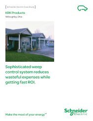
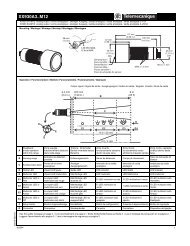
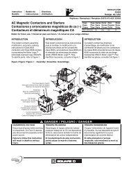
3 System overview<br />
The described component is a part of the <strong>PacDrive</strong> System. The <strong>PacDrive</strong> System is<br />
the complete control system that consists of several single components, depending<br />
on its application.<br />
Figure 3-1: <strong>PacDrive</strong> System overview<br />
<strong>PacDrive</strong> <strong>Controller</strong> Family<br />
The <strong>PacDrive</strong> <strong>Controller</strong>, microprocessor-based control hardware with the VxWorks<br />
real-time operating system, centrally implements the PLC and motion functions. A<br />
<strong>PacDrive</strong> <strong>Controller</strong> synchronizes, coordinates, and creates the motion functions for<br />
maximum<br />
• 8 drives for the <strong>PacDrive</strong> <strong>Controller</strong> C200<br />
• 2 drives for the <strong>PacDrive</strong> <strong>Controller</strong> C200 A2<br />
• 16 drives for the <strong>PacDrive</strong> <strong>Controller</strong> <strong>C400</strong><br />
• 8 drives for the <strong>PacDrive</strong> <strong>Controller</strong> <strong>C400</strong> <strong>A8</strong><br />
• 99 drives for the <strong>PacDrive</strong> <strong>Controller</strong> C600<br />
of a food and packaging machine.<br />
Many different HMIs are used for the HMI tasks. Whether it is low-cost clear text or<br />
IPC, it is no problem for the flexible <strong>PacDrive</strong> <strong>Controller</strong>.<br />
The <strong>PacDrive</strong> P600 <strong>Controller</strong> is additionally equipped with a full-fledged PC. Due to<br />
its PC-based architecture, it can perform HMI tasks with no problem in addition to the<br />
usual motion functions.<br />
TM<br />
3.3 Rest dangers<br />
ELAU GmbH <strong>PacDrive</strong> <strong>Controller</strong> <strong>C400</strong> / <strong>C400</strong> <strong>A8</strong> Page 15
3 System overview<br />
<strong>PacDrive</strong> Power Supply PS-5<br />
The <strong>PacDrive</strong> PS-5 Power Supply unit features modern technology and a compact<br />
and closed construction for switching cabinet installation. Each <strong>PacDrive</strong> iSH has a<br />
<strong>PacDrive</strong> PS-5 that can be quickly installed with a single connection line. Which means<br />
that the PS-5 fits seamlessly into the extremely flexible, modular drive concept.<br />
The highlights<br />
• Integrated mains filter and bleeder<br />
• Intermediate circuit power for up to 25 iSH (depending on the application)<br />
• Integrated SERCOS interface<br />
• Fully diagnosable due to integrated controller<br />
• Simple mounting<br />
<strong>PacDrive</strong> Distribution Box DB-5<br />
<strong>PacDrive</strong> DB-5 is the link between PS-5 and iSH. Optionally, 1 to 4 iSH Motors can be<br />
connected depending on the number of drives. When operating more than 4 drives<br />
simply expand the system using one or more DB-5s.<br />
The highlights<br />
• 1-4 connections for iSH motors or easily expandable with more DB-5s<br />
• Easy to expand<br />
<strong>PacDrive</strong> Intelligent Servo Module iSH<br />
The innovative iSH combines the motor, power amplifier, and the digital servo con‐<br />
troller for an axis in a space-saving housing. Due to the compact build type with an<br />
integrated controller, it is eminently suitable for a decentralized setup.<br />
It is available with single or multi-turn encoders and configures itself in the iSH with<br />
the aid of the electronic type plate.<br />
The highlights<br />
• Compact type of construction<br />
• 3.5 times peak torque<br />
• Integrated SERCOS interface<br />
• High-resolution single or multi-turn encoder<br />
• Protection class IP65<br />
• Simple wiring<br />
• Superior reliability<br />
Page 16 <strong>PacDrive</strong> <strong>Controller</strong> <strong>C400</strong> / <strong>C400</strong> <strong>A8</strong> ELAU GmbH
Highly dynamic<br />
AC Servo Mo‐<br />
tors<br />
<strong>PacDrive</strong> Servo Amplifier MC-4<br />
The digital Servo Amplifier MC-4 features compact, closed, wall-mountable construc‐<br />
tion as well as state of the art technology. For the innovative MC-4, the power supply<br />
unit, the final stage and the software servo regulator for an axis are housed in a spacesaving<br />
housing. Because it communicates with the <strong>PacDrive</strong> <strong>Controller</strong> exclusively via<br />
fiber optic cable, it is also suitable for peripheral layout. It does not require a user<br />
program, processes single or multi-turn encoders, and configures itself using the elec‐<br />
tronic type plate in the SH-Motor.<br />
Highlights of the <strong>PacDrive</strong> MC-4<br />
• Global voltage range<br />
• Integrated power supply unit<br />
• Max. 34.5/69 kVA output<br />
• Automatic motor detection<br />
• Minimal design<br />
• Inverter Enable safety input<br />
• 250 % overload<br />
• Integrated SERCOS interface<br />
<strong>PacDrive</strong> SH Servo motor<br />
The AC servo motors of the SH series meet the highest demands on dynamics and<br />
precision. Five flange sizes with different grades of torque offer the right drive solution<br />
for virtually any application. New winding technology with single tooth winding enables<br />
compact sizes and reduces production costs compared to traditional motors.<br />
Compared to other AC servo motors, the SH motor has a low internal moment of inertia<br />
and a high overload capability, which allow the motor to satisfy any requirement with<br />
regard to precision, dynamics and efficiency.<br />
The SH motors are compatible with SM Motors and available in five different flange<br />
sizes:<br />
• SH-055<br />
• SH-070<br />
• SH-100<br />
• SH-140<br />
• SH-205<br />
Brief summary of technical data:<br />
• Developed for the highest dynamics and precision<br />
• Single tooth winding<br />
• Compact size<br />
• High power density<br />
• Low internal moment of inertia<br />
• High overload capability<br />
• High resistance to winding damages<br />
• Low detent torque<br />
3.3 Rest dangers<br />
ELAU GmbH <strong>PacDrive</strong> <strong>Controller</strong> <strong>C400</strong> / <strong>C400</strong> <strong>A8</strong> Page 17
4 Indicators, control elements, diagnosis<br />
4 Indicators, control elements, diagnosis<br />
The <strong>PacDrive</strong> System supports the user with its comprehensive diagnostic sys‐<br />
tem.<br />
The diagnostic messages can be read out with the Automation Toolkit EPAS-4 or in<br />
the PD-Diagnostic. The <strong>PacDrive</strong> System contains a powerful message logger in<br />
which additional diagnostic information is recorded.<br />
Diagnostic messages are usually displayed on a control panel on the machine. If an<br />
"error" occurs, read the diagnostic message on this unit and then contact the machine<br />
manufacturer.<br />
Detailed information on diagnosis is available in the Online-Help of the Automation<br />
Toolkit EPAS-4 or in the PD-Diagnostic.<br />
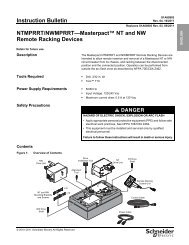
4.1 Indicators on the <strong>PacDrive</strong> <strong>C400</strong> controller<br />
<strong>PacDrive</strong><br />
<strong>C400</strong><br />
pow<br />
wd<br />
err<br />
bus<br />
err<br />
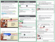
Figure 4-1: Control unit of <strong>PacDrive</strong> <strong>C400</strong> <strong>Controller</strong><br />
pow<br />
wd<br />
err<br />
bus<br />
err<br />
V00.24.23<br />
10.128.2111.103<br />
0406-0117.0601<br />
enter<br />
X21 cf-card<br />
X21 cf-card<br />
enter<br />
battery<br />
<strong>PacDrive</strong><br />
<strong>C400</strong><br />
24V/wd<br />
X1<br />
digital out<br />
X2<br />
digital in<br />
X3<br />
tp/fast<br />
X4<br />
analog in/out<br />
X5<br />
pow<br />
wd<br />
err<br />
bus<br />
err<br />
Made in Germany<br />
X21 cf-card<br />
X21 cf-card<br />
enter<br />
eth<br />
14<br />
15<br />
10<br />
phys enc<br />
X11<br />
12 13<br />
battery<br />
battery<br />
pacnet<br />
com1 rs232<br />
X17<br />
com2 rs485<br />
X18<br />
can<br />
19<br />
profibus dp<br />
20<br />
If the cover of the <strong>Controller</strong> is closed, you will see four vertically arranged indicators,<br />
which signify various operating states or errors.<br />
• pow (control voltage indicator)<br />
• wd (watchdog indicator)<br />
• err (error display)<br />
• bus err (SERCOS real-time bus error indicator)<br />
In addition to the LED displays, further information about the operating status of the<br />
controller is given on the 4-line LCD display.<br />
<strong>PacDrive</strong><br />
<strong>C400</strong><br />
24V/wd<br />
X1<br />
digital out<br />
X2<br />
digital in<br />
X3<br />
tp/fast<br />
X4<br />
analog in/out<br />
X5<br />
pow<br />
wd<br />
err<br />
bus<br />
err<br />
Line 1 currently used firmware version<br />
Made in Germany<br />
X21 cf-card<br />
X21 cf-card<br />
cf-card<br />
eth<br />
14<br />
15<br />
10<br />
phys enc<br />
X11<br />
12 13<br />
battery<br />
battery<br />
battery<br />
X21<br />
enter<br />
Line 2 current IP number of the <strong>PacDrive</strong> <strong>Controller</strong><br />
Line 3 -<br />
Line 4 FPGA-Version/Bootloader-Version/Software-Version (PIC)<br />
Page 18 <strong>PacDrive</strong> <strong>Controller</strong> <strong>C400</strong> / <strong>C400</strong> <strong>A8</strong> ELAU GmbH<br />
on / off<br />
reset<br />
pacnet<br />
battery<br />
com1 rs232<br />
X17<br />
com2 rs485<br />
X18<br />
can<br />
19<br />
profibus dp<br />
20<br />
TM<br />
on / off<br />
reset<br />
cf-card<br />
X21<br />
battery<br />
battery
****ACCU CAPACITY****<br />
TOO LOW!!<br />
BOOT ANYWAY?<br />
YES<br />
enter<br />
The horizontally arranged buttons on the controller currently have no function.<br />
Display during the boot with empty battery pack (UPS).<br />
Press the right button below the display to continue the boot and to start charging the<br />
battery pack.<br />
pow (control voltage display)<br />
The "pow" LED indicates the state of the control voltage.<br />
OFF The control voltage (24 V DC) is not available or is too low.<br />
ON Normal operation; control voltage in normal range<br />
Flashes UPS active<br />
wd (watchdog indicator)<br />
Watchdog is a hardware module to monitor the controller.<br />
OFF Normal operation<br />
ON Fatal error; reset required, reboot system<br />
A "fatal error" is a serious hardware problem or an unexpected software problem.<br />
When a "fatal error" occurs<br />
• the CPU is stopped,<br />
• the optional module is reset,<br />
• the outputs are reset and<br />
• the wd (watchdog) relay outputs are opened.<br />
err (error display)<br />
The error LED (err) indicates errors. The following table lists the possible display con‐<br />
ditions and their accompanying error descriptions.<br />
OFF Normal operation<br />
Flashes slowly (1.7 Hz) Error of class 1, 2, 3, 4 or 5 active<br />
Flashes quickly (10 Hz) <strong>Controller</strong> boot completed, last boot failed. See diagnostic message 209<br />
"last boot failed". <strong>Controller</strong> performed a minimal boot.<br />
Flashes fast and slowly alter‐<br />
nately<br />
Firmware download via SERCOS is active<br />
ON A serious error occurred during the current boot.<br />
4.1 Indicators on the <strong>PacDrive</strong> <strong>C400</strong> controller<br />
The err-LED is switched on following "Power on". Once the operating system, user<br />
configuration, user parameters and the IEC program have been loaded and the IEC<br />
program has been started successfully the err LED will switch off again. The boot<br />
procedure is now complete.<br />
ELAU GmbH <strong>PacDrive</strong> <strong>Controller</strong> <strong>C400</strong> / <strong>C400</strong> <strong>A8</strong> Page 19
4 Indicators, control elements, diagnosis<br />
eth<br />
X10<br />
bus err (SERCOS real-time bus error indicator)<br />
OFF Normal operation<br />
ON Bus error (problem with fiber-optic cable connection, e.g. transmitting<br />
power is too low or too high, cable break, etc.)<br />
The innovative iSH combines motor, final stages and the digital servo regulator for one<br />
axis in a space-saving housing. The sending power (fiber optic cable intensity) is set<br />
on the controller in the PLC configuration.<br />
Ethernet LEDs (data throughput indicator and network activity)<br />
There are two LEDs affixed to the Ethernet connection of the controller.<br />
LED yellow: ON <strong>Controller</strong> connected<br />
LED yellow: flashing/flickering Current network traffic<br />
LED yellow: OFF <strong>Controller</strong> not connected<br />
LED green: ON 100 MB connection<br />
LED green: OFF 10 MB connection<br />
Once you have opened the operating cover you have access to the controller control<br />
elements:<br />
• CompactFlashTM card slot<br />
• Battery compartment<br />
• [on / off] button<br />
• [reset] button<br />
4.2 CompactFlashTM card slot<br />
cf - card<br />
top side here<br />
X21<br />
The CompactFlash card slot is the receptacle for the permanent data storage (CF<br />
card) of the controller.<br />
How to replace the Compact Flash in case of servicing:<br />
▶ Switch off controller.<br />
▶ Hold the CF card with your thumb and forefinger and pull it out of the slot.<br />
▶ To insert, carefully place the CF card on the guide rail and push it into the device.<br />
▶ Push lightly until the card clicks in.<br />
Page 20 <strong>PacDrive</strong> <strong>Controller</strong> <strong>C400</strong> / <strong>C400</strong> <strong>A8</strong> ELAU GmbH
4.3 Battery compartment<br />
battery<br />
Maintenance<br />
interval<br />
The controller battery buffers controller data (Bios, NVRAM, time, etc.).<br />
The battery should be replaced every 6 years. After this period of time the battery must<br />
be replaced. If the device (with battery inserted) is not used for an extended period of<br />
time, you should check/replace the battery.<br />
Measurement This is how you measure the battery:<br />
▶ Replace battery and continue with the manual measurement<br />
or<br />
▶ observe the diagnostic message "037 Battery down“ in the IEC program and dis‐<br />
play it on an HMI (panel), if necessary.<br />
▶ Replace battery three days after the first diagnostic message at the latest.<br />
This is how you replace the battery:<br />
▪ You can change the battery while the controller is on or off. There is no loss of<br />
data when it is performed with the controller on. When the controller is switched<br />
off, the time period allotted for data buffering without a battery is approx. 5 minutes.<br />
WARNING<br />
THERE IS A RISK OF EXPLOSION/FIRE IF THE WRONG BATTERY IS USED.<br />
• Only use the type of battery with the following data: 3V Lithium Renata Type<br />
2450N.<br />
Failure to follow these instructions can result in death or serious injury.<br />
▶ Use insulated pliers to lightly pull the old battery out of its slot.<br />
CAUTION<br />
DANGER OF EXPLOSION WHEN REMOVING/REPLACING BATTERY!<br />
• Use a pair of suitable, insulated pliers.<br />
• When replacing the battery use tools which contain no current conducting<br />
material on the contact points.<br />
• In general, be careful not to short circuit the battery poles.<br />
• Do not recharge, dismantle or place battery in fire.<br />
A non-observance of these instructions can cause bodily injury or damage the equipment.<br />
▶ Carefully place the new battery on the guide and lightly push it into the device.<br />
4.4 Switching the controller on/off / Resetting the controller<br />
on / off<br />
4.3 Battery compartment<br />
[on / off] button<br />
▶ Press this button when the controller is switched off, completely wired and con‐<br />
nected to the power supply system and shall be switched on.<br />
ELAU GmbH <strong>PacDrive</strong> <strong>Controller</strong> <strong>C400</strong> / <strong>C400</strong> <strong>A8</strong> Page 21
4 Indicators, control elements, diagnosis<br />
reset<br />
▶ Pressing this button when the system is running will switch off the controller. If<br />
necessary, put the system in a secure position before switching it off.<br />
[reset] button<br />
▶ Press this button to reset and boot the controller.<br />
Connected MC-4 servo amplifiers have their own [reset] button.<br />
Page 22 <strong>PacDrive</strong> <strong>Controller</strong> <strong>C400</strong> / <strong>C400</strong> <strong>A8</strong> ELAU GmbH
4.5 Diagnosis<br />
4.5.1 Minimal boot of the controller<br />
If a serious boot error occurs as a result of an application error, the user can perform<br />
a minimal boot. During a minimal boot the application data (PLC configuration and IEC<br />
program) are not loaded.<br />
Perform a minimal boot as follows:<br />
▶ Boot the controller by pressing the [reset] button.<br />
The controller starts and the err - error indicator lights up.<br />
▶ Press the [reset] button again while the preset IP address is displayed.<br />
After the boot, the controller will flash quickly (10 Hz), signaling a minimal<br />
boot.<br />
The controller automatically performs a minimal boot if:<br />
• a voltage interruption of the control voltage occurs when starting the controller while<br />
the "err" indicator is illuminated.<br />
• a reset of the controller is triggered.<br />
• a serious error occurs (memory call up cannot be performed).<br />
4.5.2 Connection to <strong>PacDrive</strong> <strong>Controller</strong><br />
TCP / IP<br />
connection<br />
The connection from the (service) PC (EPAS-4) to the <strong>Controller</strong> can be made in two<br />
different ways:<br />
1. Serial connecting cable<br />
2. Ethernet connection 10/100 Base-T<br />
4.5 Diagnosis<br />
If the Windows computer being used in the service case or for commissioning has a<br />
functioning TCP/IP installation, the <strong>PacDrive</strong> <strong>Controller</strong> net management tool can be<br />
used to establish a connection. Further information on working with the <strong>PacDrive</strong> Con‐<br />
troller Net Manage commissioning tool can be found on the <strong>PacDrive</strong> EPAS-4 CD.<br />
If it is not possible to connect the EPAS-4 to the <strong>Controller</strong>, one/several of the following<br />
causes may be the problem:<br />
▶ Check IP_Address in EPAS-4 under ONLINE > Communicationparameter.<br />
- Is the channel (umbrella term for the connection parameters) set correctly?<br />
- Is the TCP/IP address set correctly?<br />
- Is the port set to "5000"?<br />
- Is Motorola byte order set to "No"?<br />
▶ Check TCP/IP settings in the PLC configuration of the project.<br />
- Is the parameter IP_SubNetMask correctly filled out?<br />
- Is the parameter IP_Address correctly entered and does it correspond to the<br />
setting under ONLINE > Communication parameters in EPAS-4?<br />
- Is the parameter IP_Gateway address correctly entered?<br />
▶ Establish serial connection to the controller.<br />
- Enter settings for a serial connection under ONLINE > Communication param‐<br />
eters (Port = "5000"(depending on the computer); Baud rate = "38400"; Parity =<br />
"No"; Stop bits = "1"; Motorola byte order = "No").<br />
- Establish serial connection.<br />
▶ Check settings in the PLC configuration of the controller.<br />
- Has the IP_SubNetMask been correctly entered?<br />
- Is the parameter IP_Address correct and does it correspond to the setting under<br />
ONLINE > Communication parameters in EPAS-4?<br />
- Has the address IP_Gateway been entered correctly?<br />
ELAU GmbH <strong>PacDrive</strong> <strong>Controller</strong> <strong>C400</strong> / <strong>C400</strong> <strong>A8</strong> Page 23
4 Indicators, control elements, diagnosis<br />
Serial<br />
connection<br />
via COM1<br />
File<br />
transfer service<br />
▶ Adjust parameter upon detection of error.<br />
- Take over parameter with ONLINE > Parameter.<br />
- Activate parameter with ONLINE > reset controller.<br />
▶ Check serial cable if jumpers are available. The connector plug assignment can<br />
be found in the EPAS-4 online help and in the "EPAS-4 <strong>Operating</strong> Instructions"<br />
▶ Check the setting for the serial interface of the PC under ONLINE > communica‐<br />
tion parameters (Port = "5000“(depending on the computer); Baud rate = "38400";<br />
Parity = "No"; Stop bits = "1"; Motorola byte order = "No").<br />
▶ Check if a modem is configured in the PLC configuration under <strong>PacDrive</strong>M ><br />
General > Com1User Modem / 1. In this case, a modem is expected at the serial<br />
interface COM1 of the controller.- Perform a minimal boot on the controller so that<br />
the serial interface COM1 is converted to the direct serial connection to EPAS-4.<br />
This is how to check whether the controller flash disk is full:<br />
▶ Log-in with EPAS-4 without file transfer.<br />
▶ Check available memory with the help of the parameter Diskfree in the PLC con‐<br />
figuration > <strong>PacDrive</strong> C600 > Memory & Disks.<br />
▶ Delete files on the flash disk using an FTP client.<br />
▶ If necessary, replace the flash disk in the controller with a flash disk of a larger<br />
storage capacity.<br />
4.5.3 Example of a diagnostic message<br />
2121 Bleeder Temperature Too High<br />
Diagnostic class (see 8.2 The Notion of 'Diagnosis Classes') (standard): 2<br />
Diagnostic code 121<br />
Reaction (see 8.3 Reactions of "drives"): B<br />
The bleeder is overloaded.<br />
▪ The drive has incorrect dimensions.<br />
▶ Check drive sizing.<br />
▪ Hardware error detected: The braking resistor or addressing is defective.<br />
▶ Contact ELAU customer service.<br />
The meaning of the diagnostic code is more thoroughly explained in the online help<br />
section of the Automation Toolkit EPAS-4 or the PD-Diagnostic.<br />
A complete list of the diagnostic messages can be found in the chapter entitled Diag‐<br />
nostic messages (see 8 Diagnosis).<br />
Page 24 <strong>PacDrive</strong> <strong>Controller</strong> <strong>C400</strong> / <strong>C400</strong> <strong>A8</strong> ELAU GmbH
5 Transport, storage, unpacking<br />
5.1 Transport<br />
5.2 Storage<br />
5.3 Unpacking<br />
5.4 Type plate<br />
▶ Avoid heavy shocks and/or vibrations during transport.<br />
▶ Check the units for visible transport damage and inform the shipping company<br />
immediately if necessary.<br />
For further information on transportation. (see 7.1 Ambient conditions)<br />
▶ Store <strong>PacDrive</strong> <strong>Controller</strong> in a clean, dry room.<br />
For further information on storage. (see 7.1 Ambient conditions)<br />
▶ Remove packaging.<br />
▶ Dispose of the packaging material in accordance with the relevant local regula‐<br />
tions.<br />
▶ Check that delivery is complete.<br />
▶ Check the delivered goods for transport damage.<br />
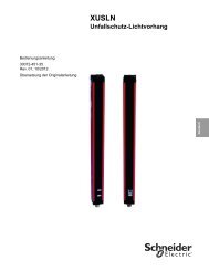
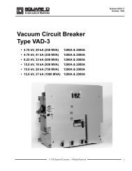
1<br />
Made in Germany<br />
02200100<br />
HW:<br />
2<br />
3 13130261-001<br />
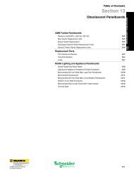
Figure 5-1: <strong>PacDrive</strong> <strong>Controller</strong> <strong>C400</strong> with type plate<br />
1 Technical type plate<br />
2 Type plate USP<br />
3 Logistic type plate<br />
<strong>PacDrive</strong> <strong>C400</strong> / 10 / 1 / 1 / 1 / 00<br />
518939.0010 U04 SW: 00.16.20<br />
5.1 Transport<br />
ELAU GmbH <strong>PacDrive</strong> <strong>Controller</strong> <strong>C400</strong> / <strong>C400</strong> <strong>A8</strong> Page 25
5 Transport, storage, unpacking<br />
Figure 5-2: Logistic type plate of the <strong>PacDrive</strong> <strong>C400</strong> <strong>Controller</strong><br />
<strong>PacDrive</strong> C200/<strong>C400</strong>/C600... Item name<br />
1313026X Item no.<br />
888067.0010 3X08 Serial number<br />
HW Hardware version<br />
SW Software version<br />
Page 26 <strong>PacDrive</strong> <strong>Controller</strong> <strong>C400</strong> / <strong>C400</strong> <strong>A8</strong> ELAU GmbH
Figure 5-3: Technical type plate of the <strong>PacDrive</strong> <strong>C400</strong>/C600 <strong>Controller</strong><br />
<strong>PacDrive</strong> <strong>C400</strong>, C600, P600 Device type, see type key<br />
Power supply Rated voltage and rated current<br />
Input Digital inputs / input voltage und input current (per input)<br />
Output Digital outputs / output voltage und rated current (per input)<br />
USV inside USV inside (12V/2000mAh)<br />
cUL cUL mark<br />
CE CE mark<br />
5.4 Type plate<br />
ELAU GmbH <strong>PacDrive</strong> <strong>Controller</strong> <strong>C400</strong> / <strong>C400</strong> <strong>A8</strong> Page 27
5 Transport, storage, unpacking<br />
5.5 Type code<br />
Product ID code <strong>C400</strong> / 10 / 1 / 1 / 1 / 00<br />
HW-Variant<br />
Processor<br />
1 = Intel Pentium M 600 MHz<br />
RAM<br />
1 = 256 MB<br />
Flash memory<br />
1 = 32 MB<br />
Optional functions<br />
Page 28 <strong>PacDrive</strong> <strong>Controller</strong> <strong>C400</strong> / <strong>C400</strong> <strong>A8</strong> ELAU GmbH
6 Installation and maintenance<br />
When carrying out the following steps, make sure to exercise with the necessary ac‐<br />
curacy and make arrangements to avoid,<br />
• injuries and material damage,<br />
• incorrect installation and programming of components,<br />
• the incorrect operation of components<br />
• and the use of non-authorized cables or modified components<br />
zu vermeiden.<br />
For warranty reasons, we recommend that you employ ELAU personnel for the initial<br />
start-up. The ELAU personnel<br />
• will check the equipment,<br />
• determine the optimal configuration<br />
• and instruct the operating staff.<br />
6.1 Initial start-up<br />
DANGER<br />
ELECTRICAL SHOCK, EXPLOSION OR ELECTRIC ARC<br />
• Observe the general construction and safety regulations for working on highcurrent<br />
electrical systems.<br />
• Operate electrical components only with connected protective conductor<br />
• After installation, check the fixed connection of the protective conductor to all<br />
electrical devices to ensure that connection complies with the connection dia‐<br />
gram.<br />
• Before enabling the device, safely cover the live components to prevent contact.<br />
• Do not touch the electrical connection points of the components when the device<br />
is switched on. First shut down drives because potentially fatal voltage can occur<br />
on the motor lines in generator operation.<br />
• Provide protection against indirect contact (DIN EN 50178 : 1997, Section 5.3.2).<br />
• Disconnect/connect the plug connectors on the cables or plug terminals on the<br />
device only when the system is deactivated (de-energized).<br />
Failure to follow these instructions will result in death or serious injury.<br />
ELECTROSTATIC DISCHARGE<br />
CAUTION<br />
• Do not touch any of the connections or components.<br />
• Discharge any existing static charge by touching a grounded metallic surface<br />
such as a grounded housing.<br />
• Prevent electrostatic charges; e.g., by wearing appropriate clothing.<br />
Failure to follow these instructions can result in equipment damage.<br />
6.1 Initial start-up<br />
This is how you prepare the initial start-up:<br />
Testing<br />
▶<br />
▶<br />
Remove packaging.<br />
Dispose of the packaging material in accordance with the relevant local regula‐<br />
tions.<br />
▶ Check that delivery is complete.<br />
ELAU GmbH <strong>PacDrive</strong> <strong>Controller</strong> <strong>C400</strong> / <strong>C400</strong> <strong>A8</strong> Page 29
6 Installation and maintenance<br />
▶ Check device for sound condition.<br />
WARNING<br />
DAMAGED OR MODIFIED DRIVE SYSTEMS<br />
• Damaged drive systems must be neither mounted nor commissioned.<br />
• Do not modify the drive systems.<br />
• Return defective devices to ELAU GmbH.<br />
Failure to follow these instructions can result in death or serious injury.<br />
▶ Check data against type plates.<br />
▶ Observe requirements for the installation location.<br />
▶ Observe requirements for the protection class and the EMC rules.<br />
▶ Then install <strong>PacDrive</strong> controller.<br />
How to wire the <strong>PacDrive</strong> <strong>Controller</strong>:<br />
▶ Connect devices, beginning with the ground conductor.<br />
▶ Check if the terminals are securely fastened and the necessary cable cross sec‐<br />
tions are correct.<br />
▶ Check that shielding is completely correct.<br />
▶ Eliminate the possibility of short circuits and interruptions.<br />
▶ Check the continuity of the protective conductor system.<br />
This is how you connect the control voltage:<br />
▶ Check the power supply voltage and control voltage.<br />
▶ Connect external 24 V DC control voltage.<br />
The devices initialze and the LEDs should display the following:<br />
<strong>Controller</strong> during initialization: pow: ON, err: ON, buserr: any state, wd: ON<br />
<strong>Controller</strong> after initialization: pow: ON, err: FLASHES or OFF, buserr: OFF, wd: OFF<br />
How to finish the initial start-up:<br />
▶ Check safety functions such as the EMERGENCY OFF switch.<br />
This is how you connect the mains voltage:<br />
▶ Activate EMERGENCY STOP switch.<br />
▶ Connect mains voltage.<br />
▶ Check status displays for proper function.<br />
▶ Release EMERGENCY OFF switch and activate ON switch.<br />
This is how you move the axis:<br />
▶ When moving the axis for the first time, use a reliable, tested application program<br />
which covers the following motions / functions:<br />
- the correct direction of rotation of the axis,<br />
- the correct setting of the limit switches and<br />
- the braking distance in both directions.<br />
This is how you transmit the configuration and the program:<br />
▶ Transfer the project with EPAS-4 Automation Toolkit onto the <strong>PacDrive</strong> <strong>Controller</strong>.<br />
Page 30 <strong>PacDrive</strong> <strong>Controller</strong> <strong>C400</strong> / <strong>C400</strong> <strong>A8</strong> ELAU GmbH
DANGEROUS MOVEMENTS<br />
WARNING<br />
• Ensure that no one is in the danger zone.<br />
• Remove all tools, loose parts and other working aids not belonging to the<br />
axis/machine/system from the area of movement.<br />
• Engaged the engine only after the function test has been successfully per‐<br />
formed.<br />
Failure to follow these instructions can result in death or serious injury.<br />
6.1 Initial start-up<br />
This is how you perform the function test:<br />
▶ Check devices and wiring again.<br />
▶ If you haven't already done it, connect the mains voltage.<br />
▶ Carry out function test using a checklist for axis/machine/system functions.<br />
▶ Resume system operation according to the operating manual (from the machine<br />
manufacturer and servo amplifier).<br />
ELAU GmbH <strong>PacDrive</strong> <strong>Controller</strong> <strong>C400</strong> / <strong>C400</strong> <strong>A8</strong> Page 31
6 Installation and maintenance<br />
6.2 Configuration, homing and programming<br />
The <strong>PacDrive</strong> System is adapted to your task using the EPAS-4 Automation Toolkit.<br />
The system will be configured and programmed according to IEC 61131-3 in EPAS-4.<br />
FAULTY PROGRAM CHANGES<br />
CAUTION<br />
• Program changes may only be carried out by trained personnel with detailed<br />
knowledge of the system.<br />
• Changes may only be carried out by your machine supplier or by ELAU employ‐<br />
ees.<br />
• ELAU is not liable for damages caused by unauthorized program changes.<br />
Failure to follow these instructions can result in equipment damage.<br />
Page 32 <strong>PacDrive</strong> <strong>Controller</strong> <strong>C400</strong> / <strong>C400</strong> <strong>A8</strong> ELAU GmbH
6.3 Electromagnetic compatibility, EMC<br />
Switch cabinet<br />
layout<br />
Shielded ca‐<br />
bles<br />
ERROR OF SIGNALS AND DEVICES<br />
WARNING<br />
• Defective signals may cause unexpected device reactions.<br />
• Check the correct execution of the EMC measures.<br />
Non-compliance with these precautions may cause death, serious injuries or material damage.<br />
The prerequisite for compliance with the specified limit values is an EMC compatible<br />
layout. Comply with the following specifications:<br />
Measures on the EMC Target<br />
Use galvanized or chromium-plated sub plates, bond metallic parts<br />
across large surface areas, remove paint layer on supporting surface.<br />
Ground switch cabinet, door and sub-plates by means of grounding strips<br />
or grounding cables with a cross-section of 10 mm2 (AWG 6).<br />
Good conductivity by surface<br />
area contact<br />
Reduce emission.<br />
Supplement switch devices such as contactors, relays or magnetic Reduce mutual interference<br />
valves with interference suppression combinations or spark blow-out el‐ coupling.<br />
ements (e.g. diodes, varistors, RC elements).<br />
Fit power and control components separately. Reduce mutual interference<br />
coupling.<br />
Measures on the EMC Target<br />
Place cable shields on the surface, use cable clamps and grounding<br />
strips.<br />
At the switch cabinet outfeed, connect the shield of all shielded cables<br />
via cable clamps to the sub plate across large surface areas.<br />
Ground shields of digital signal cables on both sides across large surface<br />
areas or via conducting connector housings.<br />
Reduce emission.<br />
Reduce emission.<br />
Reduce interference action on<br />
signal cables, reduce emis‐<br />
sions.<br />
Ground shield of analog signal cables directly on the device (signal in‐ Reduce grounding loops by<br />
put), insulate the shield at the other cable end or ground the same via a low frequency interferences.<br />
capacitor, e.g. 10 nF.<br />
Use only shielded motor supply cables with a copper braid and at least<br />
85% cover, ground shield on both sides across a large surface area.<br />
Specifically discharge interfer‐<br />
ence currents, reduce emis‐<br />
sions.<br />
Cable routing Measures on the EMC Target<br />
Do not route field bus cables and signal cables together with cabling for Reduce mutual interference<br />
direct and alternating voltages above 60 V in the same cable duct (field coupling.<br />
bus cables can be routed together with signal cables and analog cables<br />
in the same duct).<br />
Recommendation: Routing in separated cable ducts with a distance of<br />
at least 20 cm.<br />
Keep the cables as short as possible. Do not install any unnecessary<br />
cable loops, short cable routing from a central grounding point in the<br />
switch cabinet to the external grounding connection.<br />
Insert a potential equalization conductor for installations with<br />
• large surface installation<br />
• different voltage infeeds<br />
• networking across buildings<br />
6.3 Electromagnetic compatibility, EMC<br />
Reduce capacitive and induc‐<br />
tive interference couplings.<br />
Reduce current on cable<br />
shield, reduce emissions.<br />
ELAU GmbH <strong>PacDrive</strong> <strong>Controller</strong> <strong>C400</strong> / <strong>C400</strong> <strong>A8</strong> Page 33
6 Installation and maintenance<br />
Measures on the EMC Target<br />
Use fine wire potential equalization conductor. Discharging of high frequency<br />
interference currents.<br />
If motor and machine are not connected in a conducting fashion, e.g. due<br />
to an insulated flange or a connection not across a full surface, the motor<br />
must be grounded via a grounding cable > 10 mm2 Reduce emissions, increase<br />
interference resistance.<br />
(AWG 6) or a ground‐<br />
ing strip.<br />
Use twisted pair for 24 V dc signals. Reduce interference action on<br />
signal cables, reduce emis‐<br />
sions.<br />
Power supply Measures on the EMC Target<br />
Motor and en‐<br />
coder cables<br />
Additional<br />
measures for<br />
improving the<br />
EMC<br />
Operate product on mains with a grounded neutral. Enable the effect of the inte‐<br />
grated mains filter.<br />
Protection circuit if there is a risk of overvoltage. Reduce risk of damage due to<br />
overvoltages.<br />
From an EMC point of view, motor supply cables and encoder cables are particularly<br />
critical. Only use pre-configured cables, or cables with the prescribed properties, and<br />
comply with the following EMC measures.<br />
Measures on the EMC Target<br />
Do not fit any switching elements in motor supply cables or encoder ca‐<br />
bles.<br />
Route motor supply cables with a distance of at least 20 cm to the signal<br />
cables, or insert shield plates between motor supply cable and signal<br />
cables.<br />
Reduce interference coupling.<br />
Reduce mutual interference<br />
coupling.<br />
For long cabling, use potential equalization cables. Reduce current on cable<br />
shield.<br />
Route motor supply cables and encoder cables without any separation<br />
point. 1)<br />
Reduce interference radiation.<br />
1) If a cable must be cut through for installation purposes, the cables must be connected at the point of<br />
separation by means of shield connections and metal housing.<br />
The prerequisite for compliance with the specified limit values is an EMC compatible<br />
layout. Depending on the respective application, the following measures may lead to<br />
the achievement of better results:<br />
Measures on the EMC Target<br />
Upstream connection of power chokes Reduction of the harmonic<br />
network oscillations, exten‐<br />
sion of the service life of the<br />
product.<br />
Upstream connection of external integrated mains filters Improvement of the EMC limit<br />
values.<br />
Special EMC-suitable layout, e.g. within an enclosed switch cabinet<br />
complete with 15 dB attenuation of the interferences emitted<br />
Improvement of the EMC limit<br />
values.<br />
To control and regulate the motors, the mains voltage is stored by rectification in the<br />
DC bus of the servo amplifier. This stored power is supplied to the motor by precise<br />
on and off switching using six semi-conductor switches. The steep increase/decrease<br />
in voltage places considerable demands on the dielectric strength of the motor winding.<br />
Page 34 <strong>PacDrive</strong> <strong>Controller</strong> <strong>C400</strong> / <strong>C400</strong> <strong>A8</strong> ELAU GmbH
An important additional aspect to observe is the electromagnetic compatibility (EMC)<br />
with other system components. The high rate of change of the clocked voltage gen‐<br />
erates harmonics of great intensity up into the high frequency range.<br />
CAUTION<br />
SYSTEM FAILURE DUE TO ELECTROMAGNETIC FIELDS<br />
• During installation, select the grounding option with the lowest resistance for high<br />
frequency operation (e.g. unpainted sub plate in switching cabinet).<br />
• Provide the largest possible contact surface area (skin effect).<br />
• If necessary, remove existing layers (paint) to establish electrical contact.<br />
• Lay the grounding in a star configuration from the Central Grounding Point to the<br />
corresponding connections.<br />
• Avoid looping the grounding to prevent unnecessary influences.<br />
• Use shielded cable only.<br />
• Ensure large shielding transitions.<br />
• Do not connect shields via the PIN contacts of connectors.<br />
• Observe the circuit suggestions.<br />
• Shorten motor cable to minimum length.<br />
• Avoid laying cable loops in the switching cabinet.<br />
• In conjunction with electronic controllers, do not switch inductive loads without<br />
suitable interference suppression.<br />
• Provide suitable interference suppression. To this end, use recovery diodes for<br />
direct current operation and protector type-based, industry-standard quenching<br />
circuits during alternating current activity.<br />
• Arrange the interference suppression immediately at the point of inductivity, as<br />
otherwise even more interference may be generated by the shock of the switch‐<br />
ing current on the interference suppression lines.<br />
• Avoid sources of interference instead of eliminating the effects of existing inter‐<br />
ference.<br />
• Do not arrange contacts with unsuppressed inductive loads in the same room as<br />
the <strong>PacDrive</strong> <strong>Controller</strong>. The same applies for connection lines that do not lead<br />
suppressed, switched inductances and lines that run parallel to them.<br />
• Isolate the controller from such interference sources using a Faraday cage (sep‐<br />
arately partitioned switching cabinet).<br />
• Depending on the combination of servo amplifier/motor and the cable length, use<br />
mains or motor filters and observe the <strong>PacDrive</strong> planning information hardware.<br />
Failure to follow these instructions can result in equipment damage.<br />
6.3 Electromagnetic compatibility, EMC<br />
ELAU GmbH <strong>PacDrive</strong> <strong>Controller</strong> <strong>C400</strong> / <strong>C400</strong> <strong>A8</strong> Page 35
6 Installation and maintenance<br />
6.4 Maintenance, repair, cleaning<br />
6.4.1 Repair<br />
6.4.2 Cleaning<br />
Proceed as follows in case of repair:<br />
▶ Fill in the fault report form (see 10.5 Fault report form) in the attachment (can also<br />
be sent per Fax).<br />
▶ If possible, replace faulty components (see 6.6 Device replacement).<br />
▶ Send faulty components back to ELAU.<br />
How to remove dust and foreign objects from the <strong>PacDrive</strong> Drive:<br />
▶ De-energize<strong>PacDrive</strong> <strong>Controller</strong><br />
▶ Remove <strong>PacDrive</strong> <strong>Controller</strong>.<br />
It is not possible to test in advance all materials of the Schneider Electric product<br />
range as used at present and in the future for compatibility with the cleaning agents<br />
available on the market.<br />
CAUTION<br />
DAMAGE CAUSED BY CLEANING AGENTS<br />
• Before using a cleaning agent, carry out a compatibility test in relation to the<br />
cleaning agent and the component affected.<br />
• Do not use alkaline detergent as the polycarbonate can lose its stability if<br />
you come into contact with it.<br />
• Do not use any chloride-containing cleaning agents as these corrode the<br />
stainless steel and in particular the welds, and thus reduce the strength of<br />
the mechanics.<br />
Failure to follow these instructions can result in equipment damage.<br />
For more information on the material properties of your component (see 7.3 Me‐<br />
chanical and electrical data).<br />
▶ Then blow out <strong>PacDrive</strong> <strong>Controller</strong> with dry pressurized air (max. 1 bar).<br />
6.5 Spare part inventory<br />
Keep a stock of the most important components to make sure the equipment is func‐<br />
tioning and ready for operation at all times.<br />
You may only exchange units with the same hardware configuration and the same<br />
software version.<br />
▶ Indicate the following information on the spare part order:<br />
Item name: e.g. <strong>PacDrive</strong> <strong>C400</strong> / 10 / 1 / 1 / 1 / 00<br />
Item no.: e.g. 13130261<br />
Hardware code: e.g. HW: 02200100<br />
Software version: e.g. SW: 00.16.20<br />
This information can be found on the type plate (see 5.4 Type plate).<br />
Page 36 <strong>PacDrive</strong> <strong>Controller</strong> <strong>C400</strong> / <strong>C400</strong> <strong>A8</strong> ELAU GmbH
6.6 Device replacement<br />
DANGER<br />
ELECTRICAL SHOCK, EXPLOSION OR ELECTRIC ARC<br />
• Observe the general construction and safety regulations for working on highcurrent<br />
electrical systems.<br />
• Operate electrical components only with connected protective conductor<br />
• After installation, check the fixed connection of the protective conductor to all<br />
electrical devices to ensure that connection complies with the connection dia‐<br />
gram.<br />
• Before enabling the device, safely cover the live components to prevent contact.<br />
• Do not touch the electrical connection points of the components when the device<br />
is switched on. First shut down drives because potentially fatal voltage can occur<br />
on the motor lines in generator operation.<br />
• Provide protection against indirect contact (DIN EN 50178 : 1997, Section 5.3.2).<br />
• Disconnect/connect the plug connectors on the cables or plug terminals on the<br />
device only when the system is deactivated (de-energized).<br />
Failure to follow these instructions will result in death or serious injury.<br />
How to replace the <strong>PacDrive</strong> <strong>Controller</strong>:<br />
IMPROPER REPLACEMENT<br />
CAUTION<br />
• Do not open the the <strong>PacDrive</strong> <strong>Controller</strong> for commissioning or replacement.<br />
Failure to follow these instructions can result in equipment damage.<br />
CAUTION<br />
FAULTY REPLACEMENT OR OPENING OF CONTROLLER<br />
• Do not open the the <strong>PacDrive</strong> <strong>Controller</strong> for commissioning or replacement.<br />
• In addition to the following instructions, you must observe the machine manu‐<br />
facturer's specifications when replacing the the <strong>PacDrive</strong> <strong>Controller</strong>.<br />
• Replace defective devices as a whole.<br />
Failure to follow these instructions can result in equipment damage.<br />
ELECTROSTATIC DISCHARGE<br />
CAUTION<br />
• Do not touch any of the connections or components.<br />
• Discharge any existing static charge by touching a grounded metallic surface<br />
such as a grounded housing.<br />
• Prevent electrostatic charges; e.g., by wearing appropriate clothing.<br />
Failure to follow these instructions can result in equipment damage.<br />
6.6 Device replacement<br />
In addition to the following instructions, you must observe the machine manufacturer's<br />
specifications when replacing devices.<br />
ELAU GmbH <strong>PacDrive</strong> <strong>Controller</strong> <strong>C400</strong> / <strong>C400</strong> <strong>A8</strong> Page 37
6 Installation and maintenance<br />
How to de-energize the system:<br />
▶ For voltages higher than 30 V AC or 42.2 V DC, set the main switch to the "OFF<br />
position".<br />
▶ Secure main switch against restart in order to disconnect the <strong>PacDrive</strong> <strong>Controller</strong><br />
from mains or the power supply.<br />
▶ Wait at least 5 minutes after switching off before you work on the <strong>PacDrive</strong> Con‐<br />
troller.<br />
▶ Discharge DC bus.<br />
▶ Before working on the equipment, check the DC bus with a measuring instrument<br />
to make sure that it is de-energized (< 50V).<br />
▶ Disconnect cables of the controller.<br />
▶ Remove the screws from the top and bottom of the housing.<br />
▶ Remove <strong>PacDrive</strong> <strong>Controller</strong> and replace as a complete unit.<br />
▶ Install New controller and tighten screws.<br />
▶ Connect <strong>Controller</strong> according to the machine's circuit diagram.<br />
DANGER<br />
WRONG CONFIGURATION OF NEW CABLES<br />
• If you are not using prefabricated ELAU cables, make sure that the config‐<br />
uration of the new cables complies with the connection diagram of the ma‐<br />
chine manufacturer.<br />
Failure to follow these instructions will result in death or serious injury.<br />
▶ Following replacement of the <strong>PacDrive</strong> <strong>Controller</strong> proceed as for the initial startup.<br />
Proceed as follows for start-up:<br />
▶ Import the user project again using a PC on which the automation toolkit EPAS-4<br />
is installed.<br />
or<br />
▶ Remove the already used CompactFlash card of the controller that has to be re‐<br />
paired and insert it into the new controller.<br />
▶ Ensure that the card is functional.<br />
▶ Store the <strong>PacDrive</strong> controller in a suitable transport packaging.<br />
▶ Put the system back in operation.<br />
Page 38 <strong>PacDrive</strong> <strong>Controller</strong> <strong>C400</strong> / <strong>C400</strong> <strong>A8</strong> ELAU GmbH
7 Technical data<br />
7.1 Ambient conditions<br />
Procedure Parameters Value Basis<br />
Operation Class 3K3 IEC/EN 60721-3-3<br />
Ambient temperature +5°C...+45°C<br />
Condensation Prohibited<br />
Icing Prohibited<br />
another water Prohibited<br />
Relative humidity 5% ... 85%<br />
Class 3M3<br />
Shock 70 m/s 2<br />
Vibration 5 m/s 2<br />
Transport Class 2K3 IEC/EN 60721-3-2<br />
Long-term storage in<br />
transport packaging<br />
Ambient temperature -25°C...+70°C<br />
Condensation Prohibited<br />
Icing Prohibited<br />
another water Prohibited<br />
Relative humidity 5% ... 95%<br />
Class 2M2<br />
Shock 100 m/s 2<br />
Vibration 15 m/s 2<br />
Class 1K4 IEC/EN 60721-3-1<br />
Ambient temperature -25°C...+55°C<br />
Condensation Prohibited<br />
Icing Prohibited<br />
another water Prohibited<br />
Relative humidity 5% ... 95%<br />
Table 7-1: Ambient conditions of Class C20 for switch cabinet devices (without UPS)<br />
Procedure Parameters Value Basis<br />
Operation Class 3K3 IEC/EN 60721-3-3<br />
Ambient temperature +5°C...+40°C<br />
Condensation Prohibited<br />
Icing Prohibited<br />
another water Prohibited<br />
Relative humidity 5% ... 85%<br />
Class 3M3<br />
Shock 70 m/s 2<br />
Vibration 5 m/s 2<br />
7.1 Ambient conditions<br />
ELAU GmbH <strong>PacDrive</strong> <strong>Controller</strong> <strong>C400</strong> / <strong>C400</strong> <strong>A8</strong> Page 39
7 Technical data<br />
Procedure Parameters Value Basis<br />
Transport Class 2K3 IEC/EN 60721-3-2<br />
Long-term storage in<br />
transport packaging<br />
Ambient temperature -25°C...+50°C<br />
Condensation Prohibited<br />
Icing Prohibited<br />
another water Prohibited<br />
Relative humidity 5% ... 95%<br />
Class 2M2<br />
Shock 100 m/s 2<br />
Vibration 15 m/s 2<br />
Class 1K3 IEC/EN 60721-3-1<br />
Ambient temperature -5°C...+45°C<br />
Condensation Prohibited<br />
Icing Prohibited<br />
another water Prohibited<br />
Relative humidity 5% ... 95%<br />
Table 7-2: Ambient conditions of Class C20 for switch cabinet devices (with UPS)<br />
7.2 Standards and regulations<br />
Certifications CE, cULus<br />
Table 7-3: Standards and regulations <strong>C400</strong> <strong>Controller</strong><br />
7.3 Mechanical and electrical data<br />
Category Parameters Value<br />
Product<br />
configuration<br />
Processor<br />
Type key <strong>C400</strong> up to 16 SER‐<br />
COS slaves<br />
(SERCOS slaves = MC-4, SCL,<br />
iSH)<br />
Type key <strong>C400</strong> up to 8 SERCOS<br />
slaves<br />
Order number- <strong>C400</strong> up to 16<br />
SERCOS slaves<br />
Order numbers <strong>C400</strong> up to 8<br />
SERCOS slaves<br />
<strong>PacDrive</strong> <strong>C400</strong> / 10 / 1 / 1 / 1 / 00<br />
<strong>PacDrive</strong> <strong>C400</strong> / <strong>A8</strong> / 1 / 1 / 1 / 00<br />
13 13 02 61<br />
13 13 02 61-001<br />
CPU <strong>C400</strong> up to 16 SERCOS slaves: Intel Pentium M 600 MHz<br />
RAM 256 MB<br />
<strong>C400</strong> up to 8 SERCOS slaves: Celeron M 600 MHz<br />
L2 Cache <strong>C400</strong> up to 16 SERCOS slaves: 1 MB<br />
NVRAM 128 kB<br />
CompactFlashTM card ≥128 MB<br />
<strong>C400</strong> up to 8 SERCOS slaves: 512 kB<br />
Real time clock (RTC) Yes (battery maintenance interval: 5 years)<br />
Watchdog Yes (max. 60 V < 2 A)<br />
Diagnosis Alphanumeric diagnostic display, Status LEDs<br />
<strong>Operating</strong> system Real-time operating system VxWorks<br />
Page 40 <strong>PacDrive</strong> <strong>Controller</strong> <strong>C400</strong> / <strong>C400</strong> <strong>A8</strong> ELAU GmbH
Category Parameters Value<br />
Programming<br />
languages<br />
Interfaces<br />
Output<br />
SPS output<br />
Cam<br />
sequential circuit<br />
Programming languages IEC<br />
61131-3<br />
Instruction list (IL)<br />
Ladder diagram (LD)<br />
Function block diagram (FBD)<br />
Sequential function chart (SFC)<br />
Structured text (ST)<br />
Continuous function chart (CFC)<br />
Serial interfaces COM1: RS232 (X17)<br />
COM2: RS485 (X18)<br />
Network connection Ethernet (10/100 Base-T) (X10)<br />
Field bus connections PROFIBUS DP Master/Slave (12 MBaud) (X20) or<br />
CAN (2.0A) or CANopen (X19)<br />
DeviceNet Slave (cable adapter required)<br />
EtherNet/IP Slave (projected) (optional hardware module required)<br />
Real-time bus interface SERCOS interface (16 MBaud) (X14, X15)<br />
PacNet interface 2 PacNet interfaces (X12, X13)<br />
Master encoder interfaces 1 SinCos master encoder or<br />
1 incremental master encoder (X11)<br />
HMI Interfaces RS485 (Modbus or PROFIBUS DP)<br />
Diagnostic interface for remote<br />
maintenance<br />
HMI software tools: OPC server (for Windows NT/2000/XP or Win‐<br />
dows CE)<br />
Modem<br />
Communications protocols Http<br />
Integrated trace recorder (soft‐<br />
ware oscilloscope)<br />
Integrated data logger for diag‐<br />
nostic messages<br />
Ftp<br />
SMTP (E-Mail)<br />
8 channels, resolution 1 ms<br />
27 kB<br />
<strong>C400</strong> 16 servo axes with all SERCOS cycle times<br />
<strong>C400</strong> / <strong>A8</strong> 8 servo axes with all SERCOS cycle times<br />
Max. of 255 parallel motion profiles possible<br />
Time for 1000 Bit instructions 7 µs<br />
Number of PLC processes Unlimited<br />
Type of PLC processes Continuous,<br />
periodic or<br />
Cycle time fast task 250 µs<br />
Event-controlled<br />
Nominal I/O response time 500 µs (read in data, process, set output)<br />
Number of cams Max. 256<br />
Sequential circuit Dynamic<br />
Outputs Memory or<br />
Digital outputs<br />
Inputs External master encoder<br />
Virtual master encoder<br />
Axis position<br />
Processing time 250 µs<br />
7.3 Mechanical and electrical data<br />
ELAU GmbH <strong>PacDrive</strong> <strong>Controller</strong> <strong>C400</strong> / <strong>C400</strong> <strong>A8</strong> Page 41
7 Technical data<br />
Category Parameters Value<br />
Digital inputs (X3)<br />
Analog inputs (X5)<br />
Interrupt inputs<br />
(X4)<br />
Touchprobe inputs<br />
(X4)<br />
Digital outputs (X2)<br />
Digital outputs (X5)<br />
Additional digital<br />
and analog I/Os<br />
Additional fast digi‐<br />
tal I/Os<br />
Additional Touchp‐<br />
robe inputs<br />
Number 20 (IEC61131-2)<br />
Range U IN 0 Voltage DC 0 ... 6 V<br />
Range U IN 1 Voltage DC 20 ... 33 V<br />
Input data I IN = 5 mA by U IN = 24 V<br />
Polarized Yes<br />
Input filter 1 or 5 ms can be parameterized<br />
Number 2<br />
Range U IN<br />
Range I IN<br />
-10 ... 10 V<br />
Resolution 12 Bit (5 mV)<br />
Resistor 100 kOhm<br />
-20 ... 20 mA<br />
Resolution 12 Bit, (5 μA)<br />
Resistor 500 Ohm<br />
Number: 4 (IEC61131-2)<br />
Range U IN 0 Voltage DC 0 ... 6 V<br />
Range U IN 1 Voltage DC 20 ... 33 V<br />
Input data I IN = 5 mA by U IN = 24 V<br />
Polarized Yes<br />
Input filter 0.1 or 1 ms can be parameterized<br />
Number 16 (IEC61131-2)<br />
Range U IN 0 Voltage DC 0 ... 6 V<br />
Range U IN 1 Voltage DC 20 ... 33 V<br />
Input data I IN = 5 mA by U IN = 24 V<br />
Polarized Yes<br />
Input filter TP0 to TP15 100 µs resolution<br />
TP0 to TP15 10 µs at a cycle time of 1, 2, 4 ms<br />
Number 16 (IEC61131-2)<br />
Output voltage (+UL-3 V) < U OUT < +UL<br />
Rated current I e = 250 mA per output<br />
Inrush current I emax < 2 A for 1 s<br />
Leakage current with 0 signal < 0.4 mA<br />
Transmission time 100 µs<br />
short circuit proof Yes<br />
Number 2<br />
Range U OUT<br />
-10 ... 10 V<br />
Resolution 12 Bit (5 mV)<br />
Load > 5 kOhm (max. Offset < +/- 75mV)<br />
Via field bus Max. 3,584 bytes digital/analog inputs and<br />
Max. 3,584 bytes digital/analog outputs<br />
Max. number of stations: 126 (PROFIBUS)<br />
Via PacNet Max. 128 inputs and 128 outputs<br />
Via PacNet Max. 128 Touchprobe inputs<br />
Page 42 <strong>PacDrive</strong> <strong>Controller</strong> <strong>C400</strong> / <strong>C400</strong> <strong>A8</strong> ELAU GmbH
Category Parameters Value<br />
Power supply<br />
Power supply unit DC 24 V (-15% / +25%)<br />
Power consumption Max. 85 W<br />
Uninterruptible Power Supply<br />
(UPS)<br />
max. 3,0 A without UPS<br />
max. 4,5 A without UPS<br />
Internal, optional (maintenance interval 3 years)<br />
Dimensions Dimensions packaging DxWxH (mm): 300x130x400<br />
Weight Weight (with packaging) 3.5 kg (4.1 kg)<br />
Protection class Housing IP 20<br />
Isolation class Degree of pollution 2<br />
Table 7-4: Technical data <strong>PacDrive</strong> <strong>C400</strong> <strong>Controller</strong><br />
7.3 Mechanical and electrical data<br />
ELAU GmbH <strong>PacDrive</strong> <strong>Controller</strong> <strong>C400</strong> / <strong>C400</strong> <strong>A8</strong> Page 43
7 Technical data<br />
7.4 Electrical connections<br />
X1<br />
X2<br />
X3<br />
X4<br />
X5<br />
24V/wd<br />
X1<br />
digital out<br />
X2<br />
digital in<br />
X3<br />
tp/fast<br />
X4<br />
analog in/out<br />
X5<br />
Made in Germany<br />
X21 cf-card<br />
eth<br />
14<br />
15<br />
10<br />
phys enc<br />
X11<br />
12 13<br />
Figure 7-1: Connection overview <strong>PacDrive</strong> <strong>C400</strong> <strong>Controller</strong><br />
<strong>PacDrive</strong><br />
<strong>C400</strong><br />
pow<br />
wd<br />
err<br />
bus<br />
err<br />
X21 cf-card<br />
enter<br />
battery<br />
battery<br />
pacnet<br />
com1 rs232<br />
X17<br />
com2 rs485<br />
X18<br />
can<br />
19<br />
profibus dp<br />
20<br />
X17<br />
X18<br />
X10<br />
X19<br />
X11<br />
X12<br />
X13<br />
X14<br />
X20<br />
Connection Meaning max. terminal cross-section [mm 2 ]/ [AWG] max. tightening torque [Nm]<br />
X1 Control voltage/<br />
Watchdog<br />
1.50 mm 2 - -<br />
X2 Digital outputs 1.50 mm 2 - -<br />
X3 Digital inputs 1.50 mm 2 - -<br />
X4 Touchprobe and fast<br />
digital inputs<br />
X5 Analog inputs/out‐<br />
puts<br />
1.50 mm 2 28 - 16 -<br />
1.50 mm 2 - -<br />
X10 Ethernet connection - - -<br />
X11 Master encoder (Sin‐<br />
Cos)<br />
X11 Master encoder (in‐<br />
cremental)<br />
0.25 mm 2 - 0.4<br />
0.25 mm 2 - 0.4<br />
X12/X13 PacNet - - -<br />
X14 Motion bus SER‐<br />
COS input<br />
X15 Motion bus SER‐<br />
COS output<br />
- - 0.8<br />
- - 0.8<br />
X17 Com 1 (RS232) 0.25 mm 2 - 0.4<br />
X18 Com 2 (RS485) 0.25 mm 2 - 0.4<br />
X19 CAN 0.25 mm 2 - 0.4<br />
Page 44 <strong>PacDrive</strong> <strong>Controller</strong> <strong>C400</strong> / <strong>C400</strong> <strong>A8</strong> ELAU GmbH<br />
X15
Connection Meaning max. terminal cross-section [mm 2 ]/ [AWG] max. tightening torque [Nm]<br />
X20 PROFIBUS db 0.25 mm 2 - 0.4<br />
Shielded connector - - 1<br />
Table 7-5: Connection overview <strong>PacDrive</strong> <strong>PacDrive</strong> <strong>C400</strong> <strong>Controller</strong><br />
7.4 Electrical connections<br />
ELAU GmbH <strong>PacDrive</strong> <strong>Controller</strong> <strong>C400</strong> / <strong>C400</strong> <strong>A8</strong> Page 45
7 Technical data<br />
1 5<br />
4 8<br />
Pin1<br />
Pin5<br />
Pin2<br />
Pin6<br />
Pin3<br />
Pin4<br />
Figure 7-2: Input connection<br />
X1 - control voltage and watchdog<br />
Pin Designation Meaning Range<br />
1 DC +24 V Supply voltage - 15 % / +25 %<br />
2 DC 0 V Supply voltage<br />
3<br />
+UL For digital outputs DC +24 V<br />
-15 % / +25 %<br />
4 L0 For digital inputs/outputs<br />
5<br />
6<br />
DC +24 V Supply voltage<br />
(bridged with pin 1, max. ampacity<br />
4A)<br />
DC 0 V Supply voltage<br />
(bridged with pin 2, max. ampacity<br />
4A)<br />
7 WD Watchdog relay<br />
8 WD Watchdog relay<br />
Table 7-6: Connection X1<br />
1 Internal wiring diagram - input connection of power supply (simplified)<br />
2 Internal supply voltage<br />
3 Supply voltage for digital outputs/inputs<br />
-15 % / +25 %<br />
Page 46 <strong>PacDrive</strong> <strong>Controller</strong> <strong>C400</strong> / <strong>C400</strong> <strong>A8</strong> ELAU GmbH<br />
1<br />
2<br />
3
1 9<br />
8 16<br />
1 11<br />
10 20<br />
X2 - Digital outputs<br />
Pin Designation Meaning Range<br />
1 O.00 Digital output 1 DC 20 ... 30 V<br />
2 O.01 Digital output 2 DC 20 ... 30 V<br />
3 O.02 Digital output 3 DC 20 ... 30 V<br />
4 O.03 Digital output 4 DC 20 ... 30 V<br />
5 O.04 Digital output 5 DC 20 ... 30 V<br />
6 O.05 Digital output 6 DC 20 ... 30 V<br />
7 O.06 Digital output 7 DC 20 ... 30 V<br />
8 O.07 Digital output 8 DC 20 ... 30 V<br />
9 O.08 Digital output 9 DC 20 ... 30 V<br />
10 O.09 Digital output 10 DC 20 ... 30 V<br />
11 O.10 Digital output 11 DC 20 ... 30 V<br />
12 O.11 Digital output 12 DC 20 ... 30 V<br />
13 O.12 Digital output 13 DC 20 ... 30 V<br />
14 O.13 Digital output 14 DC 20 ... 30 V<br />
15 O.14 Digital output 15 DC 20 ... 30 V<br />
16 O.15 Digital output 16 DC 20 ... 30 V<br />
Table 7-7: Connection X2<br />
X3 - Digital inputs<br />
Pin Designation Meaning Range<br />
1 l.00 Digital input 0 DC 20 ... 30 V<br />
2 l.01 Digital input 1 DC 20 ... 30 V<br />
3 l.02 Digital input 2 DC 20 ... 30 V<br />
4 l.03 Digital input 3 DC 20 ... 30 V<br />
5 l.04 Digital input 4 DC 20 ... 30 V<br />
6 l.05 Digital input 5 DC 20 ... 30 V<br />
7 l.06 Digital input 6 DC 20 ... 30 V<br />
8 l.07 Digital input 7 DC 20 ... 30 V<br />
9 l.08 Digital input 8 DC 20 ... 30 V<br />
10 l.09 Digital input 9 DC 20 ... 30 V<br />
11 l.10 Digital input 10 DC 20 ... 30 V<br />
12 l.11 Digital input 11 DC 20 ... 30 V<br />
13 l.12 Digital input 12 DC 20 ... 30 V<br />
14 l.13 Digital input 13 DC 20 ... 30 V<br />
15 l.14 Digital input 14 DC 20 ... 30 V<br />
16 l.15 Digital input 15 DC 20 ... 30 V<br />
17 l.16 Digital input 16 DC 20 ... 30 V<br />
18 l.17 Digital input 17 DC 20 ... 30 V<br />
19 l.18 Digital input 18 DC 20 ... 30 V<br />
20 l.19 Digital input 19 DC 20 ... 30 V<br />
Table 7-8: Connection X3<br />
7.4 Electrical connections<br />
ELAU GmbH <strong>PacDrive</strong> <strong>Controller</strong> <strong>C400</strong> / <strong>C400</strong> <strong>A8</strong> Page 47
7 Technical data<br />
1 11<br />
10 20<br />
X4 - Touchprobe and fast digital inputs<br />
Pin Designation Meaning Range<br />
1 T.00 Touchprobe input 0 DC 20 ... 30 V<br />
2 T.01 Touchprobe input 1 DC 20 ... 30 V<br />
3 T.02 Touchprobe input 2 DC 20 ... 30 V<br />
4 T.03 Touchprobe input 3 DC 20 ... 30 V<br />
5 T.04 Touchprobe input 4 DC 20 ... 30 V<br />
6 T.05 Touchprobe input 5 DC 20 ... 30 V<br />
7 T.06 Touchprobe input 6 DC 20 ... 30 V<br />
8 T.07 Touchprobe input 7 DC 20 ... 30 V<br />
9 T.08 Touchprobe input 8 DC 20 ... 30 V<br />
10 T.09 Touchprobe input 9 DC 20 ... 30 V<br />
11 T.10 Touchprobe input 10 DC 20 ... 30 V<br />
12 T.11 Touchprobe input 11 DC 20 ... 30 V<br />
13 T.12 Touchprobe input 12 DC 20 ... 30 V<br />
14 T.13 Touchprobe input 13 DC 20 ... 30 V<br />
15 T.14 Touchprobe input 14 DC 20 ... 30 V<br />
16 T.15 Touchprobe input 15 DC 20 ... 30 V<br />
17 F.00 Fast input 1 DC 20 ... 30 V<br />
18 F.01 Fast input 2 DC 20 ... 30 V<br />
19 F.02 Fast input 3 DC 20 ... 30 V<br />
20 F.03 Fast input 4 DC 20 ... 30 V<br />
Table 7-9: Connection X4<br />
Page 48 <strong>PacDrive</strong> <strong>Controller</strong> <strong>C400</strong> / <strong>C400</strong> <strong>A8</strong> ELAU GmbH
1 10<br />
9 18<br />
Pin1<br />
Pin3<br />
Pin2<br />
Pin10<br />
Pin12<br />
Pin11<br />
Pin4<br />
Pin8<br />
Pin5<br />
Pin14<br />
Pin6<br />
Pin9<br />
X5 - analog inputs /outputs<br />
Pin Designation Meaning Range<br />
1 AI.0 + Analog input 0+ -10 ... +10 V (*) 0 ... 20 mA (**)<br />
2 J.0 + Br. current input 0 +<br />
3 AI.0 - Analog input 0-<br />
4 A.GND 0 Analog ground 0<br />
5 12 V Out 0 Output voltage 0 12 V<br />
6 PE Shield<br />
7 AO.0 Analog output 0 -10 ... +10 V<br />
8 A.GND AO.0 Analog ground 0<br />
9 PE Shield<br />
10 AI.1 + Analog input 1+ -10 ... +10 V (*) 0 ... 20 mA (**)<br />
11 J.1 + Br. current input 1 +<br />
12 AI.1 - Analog input 1-<br />
13 A.GND 1 Analog ground<br />
14 12 V Out 1 Output voltage 1 12 V<br />
15 PE Shield<br />
16 AO.1 Analog output 1 -10 ... +10 V<br />
17 A.GND AO.1 Analog ground<br />
18 PE Shield<br />
(*) Voltage metering and (**) current measurement on AI.0+ / AI.0- (Pin 1 / Pin 3) and AI.1+ / AI.1- (Pin 10 /<br />
Pin 12)<br />
Figure 7-3: Input connection<br />
(**) Current measurement via bridging to J.0+ (Pin 2) or J.1+ (Pin 11).<br />
Table 7-10: Connection X5<br />
PE<br />
R1<br />
R2<br />
AGND<br />
R7<br />
R8<br />
+12V<br />
+12V<br />
1 Internal wiring diagram - input connections for analog inputs (simplified)<br />
2 Analog Input 1<br />
3 Analog Input 2<br />
R3<br />
R4<br />
R5<br />
R6<br />
+<br />
-<br />
+<br />
-<br />
TM<br />
R1, R2 = 500R<br />
R3 - R8 = 1k<br />
7.4 Electrical connections<br />
ELAU GmbH <strong>PacDrive</strong> <strong>Controller</strong> <strong>C400</strong> / <strong>C400</strong> <strong>A8</strong> Page 49<br />
1<br />
2<br />
3
9<br />
6<br />
9<br />
6<br />
7 Technical data<br />
1 8<br />
8 1<br />
5<br />
1<br />
5<br />
1<br />
X X11 - Master encoder (SinCos)<br />
Pin Designation Meaning Range<br />
1 REFSIN Reference Signal Sinus<br />
2 SIN Sinus trace<br />
3 REFCOS Reference Signal Cosinus<br />
4 COS Cosinus trace<br />
5 +9 V Supply voltage<br />
6 RS485- Parameter channel -<br />
7 RS485+ Parameter channel +<br />
8<br />
SC_SEL Master encoder plugged in<br />
(bridge to GND)<br />
9 GND Supply voltage<br />
Table 7-11: Connection XX11 - Master encoder (SinCos)<br />
X X11 - Master encoder (incremental)<br />
Pin Designation Meaning Range<br />
1 _UA Track A<br />
2 UA Track A<br />
3 _UB Track B<br />
4 UB Track B<br />
5 +5 V Supply voltage<br />
6 _UO Track O<br />
7 UO Track O<br />
8 - -<br />
9 GND Ground<br />
Table 7-12: Connection XX11 - Master encoder (incremental)<br />
CAUTION<br />
INTERRUPTION OF THE CONTROL CIRCUIT<br />
• Only unplug or plug the master encoder when it is in a off-circuit state.<br />
• Disconnect controller from the 24 V supply voltage.<br />
Failure to follow these instructions can result in equipment damage.<br />
X12/13 - PacNet<br />
Pin Designation Meaning Range<br />
1 TxD+ OutputTransmitData+<br />
2 TxD- OutputTransmitData-<br />
3 RxD+ InputReceiveData+<br />
4 TxC- OutputTransmitClock-<br />
5 TXC+ OutputTransmitClock+<br />
6 RxD- InputReceiveData-<br />
Page 50 <strong>PacDrive</strong> <strong>Controller</strong> <strong>C400</strong> / <strong>C400</strong> <strong>A8</strong> ELAU GmbH
6<br />
9<br />
6<br />
9<br />
6<br />
9<br />
1<br />
5<br />
1<br />
5<br />
1<br />
5<br />
Pin Designation Meaning Range<br />
7 RxC+ InputReceiveClock+<br />
8 RxC- InputReceiveClock-<br />
Table 7-13: Connection X12, X13<br />
Use only approved PacNet cables at the PacNet connection to avoid malfunction.<br />
X X17 - Com 1 (RS 232)<br />
Pin Designation Meaning Range<br />
1 DCD Data Carrier Detect<br />
2 RxD Receive Data<br />
3 TxD Transmit Data<br />
4 DTR Data Terminal Ready<br />
5 GND Signal Ground<br />
6 DSR Data Set Ready Clear To Send<br />
7 RTS Request To Send<br />
8 CTS Clear To Send<br />
9 RI Ring Indicator<br />
Table 7-14: Connection XX17<br />
X X18 - Com 2 (RS485)<br />
Pin Designation Meaning Range<br />
1 +5 VM Supply voltage<br />
2 TxD- RS485 Transmit -<br />
3 TxD+ RS485 Transmit+<br />
4 RxD+ RS485 Receive +<br />
5 RxD- RS485 Receive -<br />
6 GNDR GND receive RS485<br />
7 - Reserved<br />
8 GNDM Supply voltage<br />
9 GNDR GND receive RS485<br />
Table 7-15: Connection Xpow: ON, err: FLASHES or OFF, buserr: OFF, wd: OFF<br />
X X19 - CAN<br />
Pin Designation Meaning Range<br />
1 - Reserved<br />
2 CAN_L Bus line (low)<br />
3 GND Ground<br />
4 - Reserved<br />
5 - Reserved<br />
6 - Reserved<br />
7 CAN_H Bus line (high)<br />
8 - Reserved<br />
9 - Reserved<br />
Table 7-16: Connection XX19<br />
An adapter is available for the connection to the DeviceNet.<br />
7.4 Electrical connections<br />
ELAU GmbH <strong>PacDrive</strong> <strong>Controller</strong> <strong>C400</strong> / <strong>C400</strong> <strong>A8</strong> Page 51
9<br />
6<br />
7 Technical data<br />
5<br />
1<br />
X X20 - profibus db<br />
Pin Designation Meaning Range<br />
1 PE Shield<br />
2 - Reserved<br />
3 RxD / TxD -P Data -P<br />
4 CNTR-P Control signal P<br />
5 DGND Signal ground<br />
6 VP Supply voltage<br />
7 - Reserved<br />
8 RxD / TxD -N Data -N<br />
9 Reserved<br />
Table 7-17: Connection XX20<br />
Page 52 <strong>PacDrive</strong> <strong>Controller</strong> <strong>C400</strong> / <strong>C400</strong> <strong>A8</strong> ELAU GmbH
Connector<br />
A PROFIBUS connector must be used to connect to the 9 pole PROFIBUS outlet<br />
because the bus terminal resistors are in this connector. The possible PROFIBUS<br />
connectors with different cable outlets are illustrated below.<br />
Figure 7-4: PROFIBUS connector<br />
Bus terminal resistors<br />
For the first and last bus nodes, the terminal resistors must be switched on. Otherwise<br />
data transmission will not function properly.<br />
The shielding must be applied generously and on both sides.<br />
1<br />
2<br />
3<br />
4<br />
Figure 7-5: Position of the bus terminal resistors<br />
1 Last bus slave<br />
2 Nth bus slave<br />
3 First bus slave<br />
4 Bus terminator<br />
7.4 Electrical connections<br />
ELAU GmbH <strong>PacDrive</strong> <strong>Controller</strong> <strong>C400</strong> / <strong>C400</strong> <strong>A8</strong> Page 53
7 Technical data<br />
7.5 Dimensions<br />
ca. 235 (9.25)<br />
ca. 260 (10.23) max. Bautiefe inkl. Steckverbinder!<br />
Figure 7-6: Dimensions <strong>PacDrive</strong> <strong>C400</strong> <strong>Controller</strong><br />
268 (10.55) 24 (0.95)<br />
310 (12.2)<br />
18 (0.71)<br />
<strong>PacDrive</strong><br />
<strong>C400</strong><br />
24V/wd<br />
X1<br />
digital out<br />
X2<br />
digital in<br />
X3<br />
tp/fast<br />
X4<br />
analog in/out<br />
X5<br />
pow<br />
wd<br />
err<br />
bus<br />
err<br />
12 (0.47)<br />
6.5 (0.26)<br />
Made in Germany<br />
X21 cf-card<br />
X21 cf-card<br />
enter<br />
X10<br />
X11<br />
X12 X13<br />
X14<br />
X15<br />
can<br />
com2 rs485 com1 rs232<br />
can com2 rs485 com1 rs232<br />
296 (10.6)<br />
X17<br />
X18<br />
X19<br />
profibus dp<br />
profibus dp<br />
7 (0.28)<br />
X20<br />
7 (0.28)<br />
7 (0.28)<br />
16.6 (0.65) 70 (2.76)<br />
103.2+2 (4.06)<br />
16.6 (0.65)<br />
eth<br />
phys enc<br />
battery<br />
battery<br />
pacnet<br />
PDM_<strong>C400</strong>_Masszeichnung_de.FH8<br />
Page 54 <strong>PacDrive</strong> <strong>Controller</strong> <strong>C400</strong> / <strong>C400</strong> <strong>A8</strong> ELAU GmbH
8 Diagnosis<br />
The <strong>PacDrive</strong> system supports the user with its comprehensive diagnostic system.<br />
If the Automation System cannot follow the instructions we gave him, it should not<br />
suffer in silence but<br />
• react in a defined way as far –and as fast -as possible to prevent people from injury<br />
and the machine from damage.<br />
• give a significant message about what happened to indicate the ‘Error’ to the op‐<br />
erator and to support him in locating and removing the error!<br />
8.1 Scenarios to be met at the machine<br />
There may be jam due to obstacles while placing bottles, …<br />
There may be friction due to fouling, worn out bearings, damaged mechanics, …<br />
A: There may be jam due to obstacles while placing bottles, …<br />
8.1 Scenarios to be met at the machine<br />
So, if the gripper of the robot meets an obstacle while placing the bottles into the<br />
carton, the servo will deviate from its schedule. This deviation can be found by exam‐<br />
ining Following Error.<br />
If Following Error exceeds the given limit dramatically, there should be a reaction –for<br />
example, stopping the movement of the gripper immediately if still possible to minimize<br />
damage of bottles, cartons or mechanics. After a timeout, PositionControl will be<br />
switched off.<br />
If Following Error exceeds Following Limit ‘slightly’, there should be a message but<br />
there is no need for a reaction of the ‘reporting’ drive. The message is worth the trouble,<br />
for<br />
• programmers will use it as a criterion to launch userspecific reactions of the ma‐<br />
chine within the userprogram,<br />
• maintenance staff can gather these messages from the message logger and use<br />
them e.g. for ‘preventive maintenance’!<br />
ELAU GmbH <strong>PacDrive</strong> <strong>Controller</strong> <strong>C400</strong> / <strong>C400</strong> <strong>A8</strong> Page 55
8 Diagnosis<br />
B: There may be friction due to fouling, worn out bearings, damaged mechanics, …<br />
Friction requires ‘more than the usual amount of torque’ for a given movement or for<br />
cyclic sequences of them. Remedying this error is a bit more complex. For most of all<br />
cases, friction within an installation is not that obvious, that it immediately disturbs the<br />
schedule like the above obstacles did.<br />
Friction ‘kills’ the ServoDrive in the long run. Thus the Motor<strong>Controller</strong> takes root meansquare<br />
of torque – determined via root mean current- to detect this kind of ‘continuous<br />
overload’. … and this is what we have come to know as ‘I2t’ in the previous lesson!<br />
The above ‘warning-philosophy’ applies again:<br />
If the drive is still functional and ‘I2t’ exceeds a certain threshold, there will be only a<br />
warning, either to be used as criteria for stopping the machine in a defined way on<br />
behalf of the userprogram, or as a message to be logged in the sense of preventive<br />
maintenance.<br />
If ‘I2t’ reaches its upper limit, the current movement will be stopped immediately and<br />
PositionControl will be switched off after the timeout mentioned above!<br />
Moving synchronously to seal & cut<br />
Moving back towards next product<br />
C, D: Sealing movements may require more than admitted effective current due to<br />
‚exaggerated‘ cycle rate!<br />
The motion-profiles for the up-down-movement and the back and forth movement of<br />
the sealing-bar require acceleration- and deceleration-phases due to changing direc‐<br />
tions.<br />
Increasing cycle rate will require more and steeper(!) accel- and decel-phases per<br />
cycle and that will result in rising the effective values of torque and current!<br />
This continuous overload will be detected and invoke a reaction in order to prevent<br />
overheating the Motor or the Motor<strong>Controller</strong> above their acceptable temperature<br />
ranges!<br />
Page 56 <strong>PacDrive</strong> <strong>Controller</strong> <strong>C400</strong> / <strong>C400</strong> <strong>A8</strong> ELAU GmbH
8.2 The Notion of 'Diagnosis Classes'<br />
8.2 The Notion of 'Diagnosis Classes'<br />
‘Classification’ - in the sense of our Diagnosis Concept - is a mapping of lots of possible<br />
errors to appropriate ‘Reactions’. Thus ‘Diagnosis Classes’ are a set of carefully de‐<br />
fined ‘Reactions’ that are provided to handle exceptional situations.<br />
Let us consider some examples to shed more light on the above approach:<br />
1. We have to ‘classify’ an encoder that we are not able to read as severe so that it<br />
produces a reaction that includes switching off position control of all related drives:<br />
˗ If the encoder can not be read, the position of the respective drive is getting out<br />
of control and there is danger of colliding with other drives.<br />
To minimize damage, we have to<br />
˗ ‘de-energize’ the drive with the severe failure<br />
˗ ramp-down to standstill and de-energize additional drives that would be affect‐<br />
ed.<br />
2. If reading field-bus-signals fails, that would be less grave than no communication<br />
with the encoder mentioned above:<br />
˗ PositionControl does not depend on ‘field-bus’, So it remains active in this case.<br />
˗ Danger of injury or damage comes from the fact, that we could miss –say- a<br />
stop signal for some of the drives under consideration due to ‘No more field bus<br />
communication’: For safety-reasons, ELAU’s R&D engineers decided to stop<br />
the drives with a defined deceleration ramp in such cases<br />
3. We will ‘classify’ a short-circuited Digital output as to react on it by simply a mes‐<br />
sage (- leaving further reaction to the user-program if necessary!):<br />
˗ Pac<strong>Controller</strong> is still working properly, Motor<strong>Controller</strong>s and Motors do not re‐<br />
port any discrepancies and all conditions for Position Control are still given.<br />
˗ In this case from the point of view of Automation System there is no need to<br />
stop some movement or to switch off drives due to something ‘getting out of<br />
control’.<br />
˗ … the message about what happens is desirable for operators or service-staff<br />
to quickly find the source of the trouble!<br />
ELAU GmbH <strong>PacDrive</strong> <strong>Controller</strong> <strong>C400</strong> / <strong>C400</strong> <strong>A8</strong> Page 57
8 Diagnosis<br />
Diagnostic class Designation Priority<br />
1 Fatal error high<br />
2 Error resulting in complete shutdown<br />
3 Error resulting in single shutdown<br />
4 Error resulting in complete stop<br />
5 Error resulting in single stop (if error is triggered by an axis)<br />
6 Warning<br />
7 Message low<br />
8 Logger entry None<br />
9 Deactivated None<br />
Table 8-1: Designation of the diagnostic classes and their priority<br />
The system assigns each diagnostic message a specific diagnostic class when ena‐<br />
bled. The assignment can be overwritten with the user program (function DiagConfig‐<br />
Set() ).<br />
The following restrictions apply when overwriting an assignment:<br />
• Certain internal diagnosis codes ("Drives" with Reaction A, B and C) may only be<br />
assigned classes 1, 2 and 3 .<br />
• Reaction (A ... E), related to diagnostic messages of type "Group 1xx - Drives"<br />
cannot be changed.<br />
• Diagnostic class 8 is used by the system and may not be changed.<br />
Certain system reactions are permanently assigned to each diagnosis class:<br />
Class 1 2 3 4 5 6 7 8 9<br />
Entry in message logger X X X X X X X X -<br />
best standstill of all drives X X - - - - - - -<br />
best standstill of the triggering drive - - X - - - - - -<br />
Error stop of all drives - - - X - - - - -<br />
Error stop of the triggering drive - - - - X - - - -<br />
Inform IEC program ( DiagMsgRead() function ) X X X X X X X - -<br />
Activate ERROR LED X X X X X - - - -<br />
Configurable X X X X X X X X X<br />
Update diagnosis parameters of <strong>PacDrive</strong> controller X X X X X X - - -<br />
Update diagnosis parameters of drive X X X X X X X - -<br />
Table 8-2: Diagnosis classes and system reactions<br />
best standstill<br />
If Enable (<strong>Controller</strong>Enable and HW_Enable) is removed, then DrivePeakC is the best<br />
way to stop the drive. If used for this purpose, DrivePeakC can be controlled with<br />
LimCurrent.<br />
Error stop<br />
If <strong>Controller</strong>Stop becomes active, the drive is stopped with StopDec.<br />
Page 58 <strong>PacDrive</strong> <strong>Controller</strong> <strong>C400</strong> / <strong>C400</strong> <strong>A8</strong> ELAU GmbH
8.3 Reactions of "drives"<br />
Errors in the "drives" diagnosis group have an additional reaction.<br />
Reaction Meaning Diagnosis example<br />
A Motor immediately loses all torque;<br />
brakes engage immediately<br />
B Best automatic stop: Motor brakes with<br />
maximum deceleration, brake engages<br />
at n
8 Diagnosis<br />
error<br />
reaction "A"<br />
1<br />
0<br />
0<br />
AxisState ³3 0<br />
MC4State 0x30 0x07 0x02<br />
MC4State 0x30 0x07 0x06 0x02 BrakeCoast = TRUE<br />
current speed<br />
brake relay<br />
closed<br />
motor<br />
torque<br />
Ready<br />
closed<br />
n<br />
nmin<br />
0<br />
1<br />
0<br />
1<br />
0<br />
1<br />
0<br />
0<br />
0<br />
0<br />
0<br />
with brake<br />
Brake<br />
Coupling<br />
Time<br />
Figure 8-1: Time diagram for reaction "A"<br />
8.3.2 Time diagram for reaction "B"<br />
1<br />
with brake and<br />
BrakeCoast = TRUE<br />
3 4<br />
with BrakeCoast = TRUE<br />
2 5<br />
without brake<br />
Brake<br />
Coupling<br />
Time<br />
In case of a diagnostic message with reaction "B", to sequences can occur.<br />
Ramping down within the maximum ramp-down time<br />
BrakeCoast = FALSE<br />
In case of an error with reaction "B" (1), the axis ramps down at maximum current and<br />
the ready contact is opened. The axis comes to a standstill before expiry of the max‐<br />
imum ramp-down time (parameter StopTimeLim) (4). As soon as the actual speed<br />
becomes lower than the speed threshold (actual speed < n min) (2), the brake relay is<br />
released. After expiry of the brake coupling time (parameter BrakeCouplingTime) (3),<br />
the motor is switched to a torque-free state.<br />
In this way, error free ramping down is performed if the CoastOption (see IEC library<br />
"System" > Function CoastOptionSet) for reaction "B" is not active (bErrorCoast =<br />
FALSE).<br />
Page 60 <strong>PacDrive</strong> <strong>Controller</strong> <strong>C400</strong> / <strong>C400</strong> <strong>A8</strong> ELAU GmbH<br />
t<br />
t<br />
t<br />
t<br />
t
error<br />
reaction "B"<br />
current speed<br />
brake relay<br />
closed<br />
motor<br />
torque<br />
Ready<br />
closed<br />
1<br />
0<br />
n<br />
nmin<br />
0<br />
1<br />
0<br />
1<br />
0<br />
1<br />
0<br />
1<br />
0<br />
AxisState ³3 0<br />
MC4State 0x30 0x08 0x06 0x02<br />
0<br />
0<br />
0<br />
0<br />
2<br />
StopTimeLim<br />
BrakeCouplingTime<br />
Figure 8-2: Time diagram for reaction B (Ramping down within the max. ramp-down time)<br />
Maximum ramp-down time exceeded<br />
3<br />
4<br />
8.3 Reactions of "drives"<br />
In case of an error with reaction "B" (1), the Axis ramps down at maximum current and<br />
the ready contact is opened. The axis does not come to a standstill before expiry of<br />
the maximum ramp-down time (parameter StopTimeLim) (2) (actual speed < n min).<br />
Therefore, the brake relay is opened and error message 140 "Ramp-down time ex‐<br />
ceeded" (see 8.6.2.41 140 Ramp-down braking time exceeded) is triggered. As an<br />
error with the same reaction is already active, however, this error message does not<br />
have an effect on the axis. After expiry of the brake coupling time (parameter Brake‐<br />
CouplingTime) (3), the motor is switched to a torque-free state.<br />
In this way, during the maximum ramp-down time plus brake coupling time, ramping<br />
down is performed in a controlled and subsequently stopping is performed in an un‐<br />
controlled way (drive coasts to standstill). This only applies if CoastOption (see IEC<br />
library "System" > Function CoastOptionSet) for reaction "B" is not active (bError‐<br />
Coast = FALSE). Uncontrolled stopping does not result in an error message.<br />
ELAU GmbH <strong>PacDrive</strong> <strong>Controller</strong> <strong>C400</strong> / <strong>C400</strong> <strong>A8</strong> Page 61<br />
t<br />
t<br />
t<br />
t<br />
t
8 Diagnosis<br />
The drive behavior during uncontrolled stopping depends on whether the motor is<br />
equipped with a holding brake or not.<br />
error<br />
reaction "B"<br />
current speed<br />
brake relay<br />
closed<br />
motor<br />
torque<br />
Ready<br />
closed<br />
1<br />
0<br />
n<br />
nmin<br />
0<br />
1<br />
0<br />
1<br />
0<br />
1<br />
0<br />
1<br />
0<br />
AxisState ³3 0<br />
MC4State 0x30 0x08 0x06 0x02<br />
0<br />
0<br />
0<br />
0<br />
with brake<br />
StopTimeLim<br />
BrakeCouplingTime<br />
without brake<br />
Figure 8-3: Time diagram for reaction "B" (maximum ramp-down time exceeded)<br />
Page 62 <strong>PacDrive</strong> <strong>Controller</strong> <strong>C400</strong> / <strong>C400</strong> <strong>A8</strong> ELAU GmbH<br />
2<br />
3<br />
t<br />
t<br />
t<br />
t<br />
t
8.3.3 Shutting off<br />
Figure 8-4: The system switches off the drive due to reaction A or reaction B (see parameter<br />
AxisState)<br />
Condition ‚Enable‘ goes FALSE due to detection of an error with certain ‚severity‘.<br />
AxisState moves from ‚3’ to ‚6‘ then finally to ‚0‘ due to the lost condition<br />
According to ‚severity‘, the drive is disengaged following the above rules.<br />
Note: The system will drop the Ready-Contact if MC-4 errors with reaction A and B occur! … thus<br />
de-energizing all drives ‚fed‘ from the respective MainsContactor!<br />
AxisState is stuck at ‚0‘ due to 'error reaction …'<br />
8.3 Reactions of "drives"<br />
… and once the system should be stuck in State “0”, inspection of the respective group<br />
of conditions within the ‘State Folder’ of PLC-Configuration will tell us how to proceed!<br />
ELAU GmbH <strong>PacDrive</strong> <strong>Controller</strong> <strong>C400</strong> / <strong>C400</strong> <strong>A8</strong> Page 63
8 Diagnosis<br />
8.3.4 Stopping<br />
Figure 8-5: The system stops the drive due to errors with reaction C (see parameter Axis‐<br />
State)<br />
'<strong>Controller</strong> Stop' required due to 'Reaction' „C“.<br />
Drive in 'deceleration-phase'<br />
Drive stopped and still in PositionControl; System 'refuses' moving instructions.<br />
Error removed and DiagMsg acknowledged: Back to accepting & processing moving instructions.<br />
8.3.5 De-energizing the axes<br />
Under certain circumstances Health & Safety Regulations imperatively require ‘deenergizing’<br />
the machine to prevent injury to people.<br />
CAUTION<br />
Thus the Automation System provides an interface to the according Safety Wiring and System<br />
Behaviour covers de-energizing depending on the current DiagnosisClass!<br />
Page 64 <strong>PacDrive</strong> <strong>Controller</strong> <strong>C400</strong> / <strong>C400</strong> <strong>A8</strong> ELAU GmbH
Figure 8-6: Safety Wiring: WD and rdy<br />
CAUTION<br />
‘rdy’ and ‘WD’ contacts in the above sketch will drop, if there is either a DiagMsg launching<br />
ErrorReaction A or B or if one of the components fails.<br />
Figure 8-7: Safety Wiring<br />
Interface between Safety Wiring and ErrorReactions<br />
I_InvEnableActive : I_23<br />
I_MainsWatch : I_22<br />
I_EmergencyStop : I_21<br />
8.3 Reactions of "drives"<br />
If one of the contacts of the ‘WD & rdy’-block drops, either the MainsContactor or the<br />
“MC-4 InverterEnable”-relais will drop. Both of them will de-energize the drives!<br />
ELAU GmbH <strong>PacDrive</strong> <strong>Controller</strong> <strong>C400</strong> / <strong>C400</strong> <strong>A8</strong> Page 65
8 Diagnosis<br />
“MC-4 Inverter Enable” The “MC-4 Inverter Enable” locks the PowerStage of the re‐<br />
spective Motor<strong>Controller</strong> –thus de-energizing the motors immediately!- while leaving<br />
MainsContactor engaged!<br />
8.4 Device display elements (LEDs)<br />
The LEDs signify various operating states or errors.<br />
A more detailed description of the LEDs can be found in the device-specific operating<br />
instructions (or under "<strong>PacDrive</strong> devices" in the Online Help).<br />
The following LEDs are available:<br />
• pow (control voltage indicator)<br />
Devices: MAx-4, C200, <strong>C400</strong>, C600, P600 controllers / MC-4 servo amplifier, SCL<br />
integrated servo drive, iSH intelligent servo module, PS-4 power supply, PS-5<br />
power supply<br />
• wd (watchdog indicator)<br />
Devices: <strong>Controller</strong>s MAx-4, C200, <strong>C400</strong>, C600, P600<br />
• err (error display)<br />
Devices: MAx-4, C200, <strong>C400</strong>, C600, P600 controllers / MC-4 servo amplifier, SCL<br />
integrated servo drive, iSH intelligent servo module, PS-4 power supply, PS-5<br />
power supply<br />
• bus err (SERCOS real-time bus error display)<br />
Devices: MAx-4, C200, <strong>C400</strong>, C600, P600 controllers / MC-4 servo amplifiers,<br />
PS-4 power supply, PS-5 power supply<br />
• slink (SERCOS link display)<br />
Devices: PS-5 power supply:<br />
• serr (SERCOS bus error display)<br />
Devices: PS-5 power supply:<br />
• DC bus residual voltage display<br />
Devices: PS-5 power supply, Distribution Box DB-5<br />
• slink / pow (status display)<br />
Devices: Distribution Box DB-5<br />
• slink / serr (status display)<br />
Devices: Distribution Box DB-5<br />
8.4.1 LED red "bus err" (SERCOS real-time bus error)<br />
The "bus err" – LED (SERCOS) on <strong>PacDrive</strong> components allows fast and easy de‐<br />
tection when a fiber-optic cable is interrupted or the intensity setting for a transmitter<br />
in the SERCOS loop is incorrect. The LED turns off when error-free telegrams are<br />
received. After booting, the master starts to send telegrams continuously. At this point,<br />
all "bus err" LEDs of the SERCOS slave (<strong>PacDrive</strong> <strong>Controller</strong>, Servo amplifier, and<br />
others) must be OFF.<br />
CAUTION<br />
The status of the "bus err" LED is undefined during the boot procedure. The "err" – LED<br />
indicates when the boot procedure is complete. The "err" – LED switches on when the BIOS<br />
starts. Once the operating system, user configuration, user parameters and the IEC program<br />
have been loaded and the IEC program has been started successfully the err LED will switch<br />
off again. The boot procedure is now complete.<br />
Page 66 <strong>PacDrive</strong> <strong>Controller</strong> <strong>C400</strong> / <strong>C400</strong> <strong>A8</strong> ELAU GmbH
<strong>Operating</strong> principle<br />
• When the fiber-optic ring is closed and the light output at the receiver is optimal,<br />
the LED is off.<br />
• If the light output at the receiver is too high or too low (high damping), the LED will<br />
glow dimly.<br />
• The further away the light output moves from the optimal reception point (i.e. too<br />
much or too little light output), the brighter the LED glows.<br />
• The LED will glow at its brightest if the fiber-optic ring is interrupted.<br />
Flickering or continuous light indicates a problem with the SERCOS input of the device.<br />
Figure 8-8: "bus err" – SERCOS slave LED (e.g. MC-4 servo amplifier) flashes<br />
Other problems in the ring can be detected via the "err" LED of the SERCOS master<br />
(e.g. <strong>C400</strong> controller).<br />
8.5 Acknowledging diagnosis messages<br />
There are two ways to acknowledge diagnosis messages:<br />
• EPAS-4 > Online > Reset diagnostic message<br />
• Function DiagQuit()<br />
CAUTION<br />
POSITION LOSS DUE TO SERIOUS SERCOS BUS ERROR!<br />
8.5 Acknowledging diagnosis messages<br />
• Acknowledge the diagnosis message only after the re-initialization or referencing<br />
of the system is secured by the IEC program.<br />
• The capability to acknowledge the diagnostic message can be switched off with<br />
the function DiagNoQuitSet().<br />
• If necessary, use the SysReset() or the PrgResetAndStart().<br />
Property damage possible!<br />
Due to the erroneous acknowledgement of diagnostic message 506 "Serious SERCOS error<br />
(MASTER)", without restarting the controller, loss of position of the axes and physical encoder<br />
(SinCos, incremental encoder) from V00.15.00 is possible.<br />
Please note that acknowledging a diagnostic message does not eliminate the cause<br />
of the error. Acknowledgement serves to confirm that I have "seen" the message. By<br />
acknowledging, the diagnostic message in the <strong>PacDrive</strong> system will be deleted. If the<br />
ELAU GmbH <strong>PacDrive</strong> <strong>Controller</strong> <strong>C400</strong> / <strong>C400</strong> <strong>A8</strong> Page 67
8 Diagnosis<br />
cause for the diagnostic message continues to exist, this diagnostic message will be<br />
recognized in the <strong>PacDrive</strong> system again.<br />
Figure 8-9: Message logger example for diagnostic messages produced again following ac‐<br />
knowledgement<br />
With the following errors it is also necessary to reset the triggering device for reasons<br />
of safety or due to the far reaching consequences of the error. This occurs with the<br />
reset button on the device or by switching the device's control voltage off and on again.<br />
• 105 "Feedback error (track monitoring)"<br />
• 107 "over-current"<br />
• 113 “Bleeder defective”<br />
• 114 "Reading error EEPROM"<br />
• 115 "Gate-power failure"<br />
• 117 "Reading error encoder EEPROM"<br />
• 118 "Error on ser. interface to encoder"<br />
• 119 "Short or ground circuit in output stage"<br />
• 138 "Prohibited motor"<br />
• 144 "DC bus short circuit"<br />
• 145 "DC bus ground circuit"<br />
• 148 "Internal voltage error 15V"<br />
• 160 "Under voltage power stage driver"<br />
• 202 "Faulty configuration file"<br />
• 203 "Faulty parameter file"<br />
• 207 "Hardware module does not exist"<br />
• 209 "Last boot failed"<br />
• 300 "Division error" up to 312 "Parameter relocation failed"<br />
• 700 "CAN Layer2 driver error"<br />
• 701 "CAN Layer2 init error"<br />
• 721 "Module not ready"<br />
• 723 "No Profibus config data"<br />
• 730 "Bad master parameter data"<br />
• 731 "Automatic bus deactivation"<br />
• 737 "Double IEC address assigned"<br />
• 738 "Config. IO data > permitted IO range"<br />
• 739 "Double profibus address assigned"<br />
• 752 "No CanOpen EDS file exists"<br />
• 753 "Initialization CanOpen module failed"<br />
• 826 "Error during PIC FW update"<br />
• 900 "Software error (suspend task)"<br />
• 901 "Software error (invalid opcode)"<br />
• 902 "Software error (page fault)"<br />
• 904 "Software error (class 1)"<br />
8.6 Diagnostic messages<br />
8.6.1 0xx "Messages" diagnostic messages<br />
Page 68 <strong>PacDrive</strong> <strong>Controller</strong> <strong>C400</strong> / <strong>C400</strong> <strong>A8</strong> ELAU GmbH
001 Diagnosis acknowledgement<br />
A diagnostic message was acknowledged.<br />
The "001 diagnosis acknowledgement" message is always entered in the message<br />
logger even if the diagnosis class (see 8.2 The Notion of 'Diagnosis Classes') of the<br />
message was set to 9 using the DiagConfigSet() function.<br />
002 Pac<strong>Controller</strong> boot started<br />
The <strong>PacDrive</strong> controller was restarted.<br />
In V00.15.00 or higher, the firmware version is shown in the ext. diagnosis in the mes‐<br />
sage logger (e.g. FW V00.15.00).<br />
003 Pac<strong>Controller</strong> boot finished<br />
The startup procedure for the <strong>PacDrive</strong> controller is complete.<br />
In V00.15.00 or higher, the kernel version is shown in the ext. diagnosis in the message<br />
logger (e.g. V00.02.05 MAx4).<br />
004 IEC program started<br />
The IEC program in the <strong>PacDrive</strong> controller was restarted.<br />
005 automatic program start active<br />
The autom. program start of the IEC program is active in the <strong>PacDrive</strong> controller.<br />
006 IEC program stopped<br />
The IEC program in the <strong>PacDrive</strong> controller was stopped.<br />
007 login<br />
A login to the <strong>PacDrive</strong> controller was performed. The application that performed the<br />
login (e.g. EPAS-4) is shown in the extended diagnosis.<br />
008 logout<br />
A logout from the <strong>PacDrive</strong> controller was performed. The application that performed<br />
the logout (e.g. EPAS-4) is displayed in the extended diagnosis.<br />
009 IEC program reset<br />
A program reset was triggered with EPAS-4.<br />
010 write file<br />
8.6 Diagnostic messages<br />
File transfer via communication server. The file name is displayed in DiagExtCode.<br />
ELAU GmbH <strong>PacDrive</strong> <strong>Controller</strong> <strong>C400</strong> / <strong>C400</strong> <strong>A8</strong> Page 69
8 Diagnosis<br />
011 connect to WEBS<br />
Connecting to webserver.<br />
012 disconnect from WEBS<br />
Disconnecting from webserver.<br />
013 connect to TCP/IP server<br />
Connecting to communication server of <strong>PacDrive</strong> controller.<br />
014 disconnect from TCP/IP server<br />
Disconnecting from communication server of <strong>PacDrive</strong> controller.<br />
015 filesystem repaired<br />
Error in filesystem detected and corrected.<br />
CAUTION<br />
The filesystem is consistent again. This may also mean that files have been deleted.<br />
016 system reset<br />
warm start<br />
017 CanOpen emergency message reset<br />
A CANopen node has sent a CANopen emergency message reset to the bus.<br />
Meaning of ext. diagnosis:<br />
The system displays the node address, the error code and the error register.<br />
Structure: Nxxx Cxxxx Rxx<br />
N node address decimal CANopen node address<br />
C error code hexadecimal CANopen error code<br />
R error register hexadecimal CANopen error register.<br />
018 CanOpen node guarding error resolved<br />
A CANopen node has sent a CANopen emergency message reset to the bus.<br />
Function DiagQuit()<br />
Meaning of ext. diagnosis:<br />
The system displays the node address, the error code and the error register.<br />
Structure: Nxxx Cxxxx Rxx<br />
N node address decimal CANopen node address<br />
C error code hexadecimal CANopen error code<br />
Page 70 <strong>PacDrive</strong> <strong>Controller</strong> <strong>C400</strong> / <strong>C400</strong> <strong>A8</strong> ELAU GmbH
R error register hexadecimal CANopen error register.<br />
019 CanOpen node-specific error info<br />
A CANopen node has sent an emergency message to the bus. This diagnosis mes‐<br />
sage is always sent with the 754 "CanOpen emergency message" (see 8.6.8.30 754<br />
CanOpen emergency message)diagnosis message. It contains manufacturer-specific<br />
error data. This data consists of 5 byte values.<br />
Meaning of ext. diagnosis:<br />
Structure: b1 b2 b3 b4 b5<br />
b1-b5 hexadecimal date<br />
020 IEC cycle check changed<br />
The CycleCheckSet() function was used to enable/disable the cycle check. TRUE or<br />
FALSE is displayed in DiagExtCode.<br />
021 IEC cycle check values are changed<br />
The CycleCheckSet() function was used to change the times for monitoring single and<br />
excessive cycles time overruns. The file name is displayed in DiagExtCode.<br />
022 Calling SetTaskPriority()<br />
The SetTaskPriority() function has been called up.<br />
023 system shutdown<br />
SysShutdown is used via:<br />
• IEC function: SysShutdown()<br />
• UPS shutdown<br />
DiagExtMsg: Windows<br />
If Windows XP is shut down while the real-time system is running, then the message<br />
in the P600 <strong>PacDrive</strong> controller may have other causes:<br />
• Supply voltage is 0V => UPS shuts P600 down<br />
• The startup procedure for the <strong>PacDrive</strong> controller is complete.<br />
Up to version V00.16.xx diagnosis message 8016 “System reset” was set.<br />
024 modem connected<br />
Successful connection through a modem.<br />
025 modem disconnected<br />
Disconnection via a modem.<br />
8.6 Diagnostic messages<br />
ELAU GmbH <strong>PacDrive</strong> <strong>Controller</strong> <strong>C400</strong> / <strong>C400</strong> <strong>A8</strong> Page 71
8 Diagnosis<br />
026 user exception<br />
The function SysUserCallStack() caused an entry in the message logger. The value<br />
the function delivers is available in “Ext. Diagnosis” in the message logger. The mes‐<br />
sage logger call hierarchy function can be used to "backtrace" the function block call<br />
or nesting.<br />
027 open write file<br />
028 close write file<br />
029 UPS ok<br />
UPS monitoring reported "UPS ok" (State = 1).<br />
030 UPS active, no power<br />
UPS monitoring reports that no power is available (State = 3).<br />
031 UPS power ok<br />
UPS monitoring reports that power is available.<br />
032 Begin saving retainarea<br />
At shutdown, via UPS monitoring, saving retain area was started.<br />
033 Retainarea saved<br />
At shutdown, via UPS monitoring, saving retain area was terminated.<br />
034 IEC-tasks terminated<br />
At shutdown, via UPS monitoring, the IEC tasks were terminated.<br />
035 UPS active - system shutdown started<br />
At shutdown, via UPS monitoring, the O_OffValue output was set to switch off the UPS.<br />
036 Rebooting started<br />
At shutdown, via UPS monitoring, the power supply of the <strong>PacDrive</strong> controller was<br />
found to be OK. A reboot of the <strong>PacDrive</strong> controller was initiated.<br />
037 Battery low<br />
The battery power is below the minimum permitted value.<br />
▪ The battery voltage is too low.<br />
Page 72 <strong>PacDrive</strong> <strong>Controller</strong> <strong>C400</strong> / <strong>C400</strong> <strong>A8</strong> ELAU GmbH
▶ Change the battery for the PacNet optional module PN-4.<br />
038 Power fail<br />
▪ A power failure has occurred at the NvRam and the real-time clock (RTC). The<br />
NvRam has been deleted and the system time is incorrect.<br />
▪ The system was shut off for too long and the battery power is too low (see 8.6.1.37<br />
037 Battery low).<br />
▶ Retain range and reinitialize clock.<br />
▶ Change the battery for the PacNet optional module PN-4.<br />
039 file removed<br />
Filter type 13 “extended system messages”<br />
The system has deleted a file. Deletion is triggered when, for example, there is a<br />
symbol file that does not match the program file.<br />
The file name is shown in Ext. Diagnosis.<br />
040 file copied<br />
The system copied a file. The "Boot.sbd" symbol file is copied to "Download.sbd" when,<br />
for example, Online-Change is executed without downloading a program and the sys‐<br />
tem is reset (boot procedure).<br />
041 file renamed<br />
The system renamed a file.<br />
042 SERCOS phase changed<br />
A SERCOS phase change has occurred. The message logger Ext. diagnosis, the new<br />
phase is displayed (e.g. Phase=4).<br />
DiagExtCode Meaning<br />
Phase=0 Phase change after Phase 0<br />
Phase=1 Phase change after Phase 1<br />
Phase=1/4MBd Tells you the baud rate in V00.24.00 and higher<br />
Phase=1/xxx Internal error xxx during phase change after phase 1<br />
Phase=2 Phase change after Phase 2<br />
Phase=2/L=25% Tells you the SERCOS cycle load in percent in V00.22.00 and higher<br />
Phase=2/xxx Internal error xxx during phase change after phase 2<br />
Phase=3 Phase change after Phase 3<br />
Phase=3/2ms Tells you the SERCOS cycle time in V00.24.00 and higher<br />
Phase=3/xxx Internal error xxx during phase change after phase 3<br />
Phase=4 Phase change after Phase 4<br />
Phase=4/xxx Internal error xxx during phase change after phase 4<br />
Phase=5 Phase change after Phase 5<br />
Phase=5/xxx Internal error xxx during phase change after phase 5<br />
8.6 Diagnostic messages<br />
Table 8-3: Possible values for DiagExtCode for diagnostic message 042 "SERCOS phase<br />
change"<br />
ELAU GmbH <strong>PacDrive</strong> <strong>Controller</strong> <strong>C400</strong> / <strong>C400</strong> <strong>A8</strong> Page 73
8 Diagnosis<br />
"Phase=/":<br />
▪ An error occurred when the phase changed.<br />
▶ Check the message logger for other SERCOS diagnostic messages.<br />
▶ Note the description of these diagnostic messages.<br />
"Phase=1/-":<br />
▪ SCL-055 motors are connected to the <strong>PacDrive</strong> controller. The connection of the<br />
SCL-055 motors in the <strong>PacDrive</strong> PD-8 box is not correct.<br />
▶ Check the connection of the SCL-055 motors in the <strong>PacDrive</strong> PD-8 box. Simply<br />
placing jumpers on the desired terminals will not resolve the problem. No nodes<br />
to be plugged into the following SERCOS plug-in position.<br />
▶ Observe also the information outlined in the "SCL" and "PS-4 and PD-8" operating<br />
manuals.<br />
043 Detect SERCOS configuration<br />
The SERCOS configuration is being detected. During the detection a scan is proc‐<br />
essed.<br />
Ext. diagnosis Meaning<br />
Start Configuration scanning started.<br />
Position The physical address of the instance in the SERCOS loop and the device<br />
type is shown (e.g. instance "SLAVE1" Pos=03,Type=MC4). If the device<br />
type cannot be determined, then "Type=yyy" is eliminated.<br />
In controller version 00.23.00 or lower, the device type is not displayed.<br />
End Configuration scanning stopped.<br />
No slaves No SERCOS slaves found.<br />
Duplicate There are several devices with the same address in the SERCOS loop.<br />
The additional "xxx" indicates the loop position in which the last device<br />
with a duplicate address was found.<br />
Table 8-4: Meaning of ext. diagnosis:<br />
044 SERCOS firmware download<br />
A firmware download is being executed from the <strong>PacDrive</strong> controller to a SERCOS<br />
bus slave.<br />
The message logger Ext. diagnosis shows the following values:<br />
• DL start -> Firmware download started<br />
• Dl x OK -> Successful firmware download to slave x (x is the RealTimeBusAdr)<br />
045 error by writing in file<br />
An error has occurred while writing in a file.<br />
▪ Insufficient memory space.<br />
▶ Check to see that memory capacity is sufficient (parameter RamDiskFree, Disk‐<br />
free).<br />
▶ Increase the RamDiskSize.<br />
(the default size has been increased from 128 kBytes to 1 MByte in V00.16.10<br />
and higher).<br />
▪ An attempt was made to write a trace file to the RAM disk (“ram0”).<br />
Page 74 <strong>PacDrive</strong> <strong>Controller</strong> <strong>C400</strong> / <strong>C400</strong> <strong>A8</strong> ELAU GmbH
Duration of the<br />
update<br />
▶ Increase the RamDiskSize.<br />
(the default size has been increased from 128 kBytes to 1 MByte in V00.16.10<br />
and higher).<br />
046 FPGA firmware download<br />
This diagnosis message is triggered after the FPGA (<strong>C400</strong>, C600 and P600) is pro‐<br />
grammed or an error occurs.<br />
The various causes for this message are displayed through different external diagnosis<br />
codes. Below is a summary of all external diagnosis codes along with their causes and<br />
means of correction:<br />
DiagExtCode: C6_xpxx.esv (z.B. C6_0301.esv) oder C6_xpxx.xsv (z.B. C6_0301.xsv)<br />
▪ The FPGA firmware was programmed successfully. The DiagExtCode now indi‐<br />
cates the name of the programmed FPGA file.<br />
▶ -<br />
DiagExtCode: PinOut "p" (e.g. PinOut 3)<br />
▪ No C6_xpxx.xsv file with a matching pinout was found on the flash disk (<strong>C400</strong> or<br />
C600) or hard disk. (P600). xpxx corresponds to the FPGA firmware version. The<br />
FPGA programming was not executed. The PinOut number "p" contained in the<br />
file name indicates the required hardware version. i.e. a certain hardware version<br />
is required for an FPGA version.<br />
▶ Contact ELAU customer service to obtain the correct FPGA version for your hard‐<br />
ware.<br />
047 PIC firmware download<br />
The firmware of the PIC controller (on the <strong>PacDrive</strong> controller <strong>C400</strong>, C600 or P600) is<br />
being replaced. The extended diagnosis code shows the name of the firmware file (e.g.<br />
“c6p_0510.bin”).<br />
If an error occurs during the firmware exchange, the 826 "PCI update error" (see<br />
8.6.9.27 826 Error During PIC FW Update)diagnosis message will be triggered.<br />
048 BT-4 firmware download<br />
The firmware of the BT-4/DIO1 or BT-4/ENC1 bus terminal is being exchanged.<br />
In the following HW versions or higher, an automatic FW update of the connected<br />
BT-4/DIO1 bus terminal is possible with controllers C600, C600, C-4 and P1:<br />
• P600/C600/<strong>C400</strong> with FPGA version x311 or higher<br />
• C200 with FPGA version x209 or higher<br />
Other requirements:<br />
• Firmware file for BT-4/DIO1: "BD1_xxxx.ESV"<br />
• Firmware file for BT-4/ENC1 : "BE1_xxxx.ESV"<br />
To execute the update, the firmware file for the BT-4/DIO1 or BT-4/ENC1 bus terminal<br />
must be copied to the root directory of the controller. The update will be automatically<br />
executed at the next startup.<br />
<strong>Controller</strong>s <strong>C400</strong>, C600 and P600: about 1 minute / bus terminal<br />
<strong>Controller</strong> C200: approx. 3.5 minutes / bus terminal<br />
8.6 Diagnostic messages<br />
ELAU GmbH <strong>PacDrive</strong> <strong>Controller</strong> <strong>C400</strong> / <strong>C400</strong> <strong>A8</strong> Page 75
8 Diagnosis<br />
CAUTION<br />
After the update, all BT-4/DIO1 or BT-4/ENC1 bus terminals must be switched off and on. A<br />
standard reset on the controller is sufficient.<br />
The update will only be executed if a bus terminal has a differing firmware version.<br />
050 No reaction from Windows<br />
Windows did not react within the WinWatchDog time. The control task can react to<br />
certain events in a fast task.<br />
051 <strong>Controller</strong> type<br />
The <strong>PacDrive</strong> controller was restarted (rebooted). Shortly before the start procedure<br />
ends, the controller type will be saved as a diagnosis message in the message logger.<br />
Example:<br />
Max4/FPGA/=130f/CPU=581/AX=8/RAM=32/NRAM=32/DiskS=16<br />
CAUTION<br />
The controller type may not be displayed in full, as the message text does not have enough<br />
characters.<br />
052 Extended SERCOS diagnosis (MASTER)<br />
The "extended SERCOS diagnosis (MASTER)" is no longer needed. Use <strong>PacDrive</strong><br />
Diagnostics (SERCOS topology) and the RDISTCounter, RERRCounter, FIBBR‐<br />
Counter, MSTLateCounter and MSTEarlyCounter parameters of the SERCOS slave<br />
devices for debugging.<br />
As it is very difficult to get an exact SERCOS diagnosis and localize communication<br />
errors, especially when complex errors occur in pure SCL systems, the first stage for<br />
extended diagnosis functions was implemented in V00.16.30.<br />
<strong>Operating</strong> principle<br />
If a communication error occurs, the controller will, at specified times, record the error<br />
counter in the SERCOR memory and the pending error events (error interrupts) in the<br />
SERCOS registers.<br />
At first, these times refer to the occurrence of the first fault as a simple cycle error.<br />
Secondly, they refer to the occurrence of a multiple cycle error, which results when<br />
simple cycle errors occur directly after each other. Finally, a recording is made directly<br />
before the controller returns to phase 0.<br />
These recordings are displayed in the message logger. To prevent these messages<br />
from being displayed when a machine is shut down intentionally, they will be displayed<br />
with a delay of 10 seconds and then triggered at a lower priority level. If during this<br />
time the pending errors are acknowledged, the message will also be displayed without<br />
delay.<br />
Vorraussetzungen<br />
The following requirements must be observed when using the extended SERCOS<br />
diagnosis:<br />
Page 76 <strong>PacDrive</strong> <strong>Controller</strong> <strong>C400</strong> / <strong>C400</strong> <strong>A8</strong> ELAU GmbH
• <strong>PacDrive</strong> controller – firmware version V00.16.30 or higher<br />
• EPAS-4 as of V 16.22 or higher (PacControl CD V16 SP3)<br />
Operation<br />
Activation To activate the extended SERCOS diagnosis, the Bit0 of the TestSwitch1 must be set<br />
to 1 in the PLC configuration.<br />
The Testswitch1 may only be set in version V00.16.30 / V00.16.40 or higher. In ver‐<br />
sions above V00.16.40, expect the Testswitch to have a new purpose with different<br />
functions! The support of "Extended SERCOS diagnosis" in a newer firmware version<br />
is no longer required.<br />
Figure 8-10: Set TestSwitch1 parameter to 1 (V00.16.30 / V00.16.40)<br />
8.6 Diagnostic messages<br />
The display filter settings in the message logger must continue to include the 5th entry<br />
("additional SERCOS diagnosis"):<br />
ELAU GmbH <strong>PacDrive</strong> <strong>Controller</strong> <strong>C400</strong> / <strong>C400</strong> <strong>A8</strong> Page 77
8 Diagnosis<br />
Figure 8-11: Set the filter in the message logger for "additional SERCOS diagnosis".<br />
However, the filter settings should correspond to the basic settings in EPAS-4 V16<br />
SP3 or higher.<br />
Evaluation After a SERCOS cycle error occurs, entries can be found in the message logger in a<br />
way similar to the figure below:<br />
Figure 8-12: SERCOS interface / example of a message logger when an error occurs<br />
The usual error message for a multiple cycle error appears at the beginning of line<br />
number 6.<br />
After line number 6, the first block of the extended SERCOS diagnosis appears (line<br />
numbers 8-10).<br />
An info mark ("S:111284ms") appears at the beginning of this diagnosis block (here<br />
line number 7) and allows the block to be assigned a specific error message. In this<br />
case, a distinction is made between the three diagnosis situations:<br />
S – single SERCOS cycle error (SingleCycleError)<br />
M – multiple SERCOS cycle error (MultiCycleError)<br />
0 – switch to phase 0<br />
Page 78 <strong>PacDrive</strong> <strong>Controller</strong> <strong>C400</strong> / <strong>C400</strong> <strong>A8</strong> ELAU GmbH
The time mark (in ms) of when the error occurred is shown in connection with this error<br />
type.<br />
All axes whose receive error counter (nerr) has changed since the last diagnosis ac‐<br />
knowledgement or phase startup (line number 8) are then listed. The error counter is<br />
assigned to the axis via the "Object" and "Instance" columns.<br />
The value displayed in connection with "nerr=x" is only reset during phase startup. If<br />
more than one single SERCOS cycle error occurs during operation, the error counter<br />
will increase each time accordingly.<br />
The remaining information refers to the error status (line no. 9). Each error status is<br />
reset during each phase startup and each error acknowledgement. This information<br />
always consists of a letter and a number ("r=1"). Each error status is reset during each<br />
phase startup and each error acknowledgement.<br />
The meaning of the letter is the same as the letter in the ext. diagnosis messages for<br />
SERCOS cycle errors:<br />
R – double miss of drive telegrams (RMISS)<br />
R – double miss of the synchronous telegram (MSTMISS)<br />
F – fiberoptic break (FIBBR)<br />
1 – late reception of the synchronous telegram (MSTLATE)<br />
e – early reception of the synchronous telegram (MSTEARLY)<br />
d – receive distortion<br />
r – single miss of a drive telegram (RERR)<br />
Hence, the first diagnosis block would be interpreted as follows:<br />
8.6 Diagnostic messages<br />
"Simple SERCOS cycle error at 111284 ms. A single telegram miss at the axis_2 drive<br />
was determined".<br />
A second block follows the first block. In this case, the display of the multiple cycle<br />
error is involved, since the telegram from the axis_2 drive was missed a second time.<br />
Figure 8-13: SERCOS interface / example of a message logger when an error occurs (multiple<br />
cycle error)<br />
The multiple cycle error occurred directly in the next cycle (cycle time 4 ms) after the<br />
single cycle error and affected the axis_2 drive again. The error counter for this drive<br />
ELAU GmbH <strong>PacDrive</strong> <strong>Controller</strong> <strong>C400</strong> / <strong>C400</strong> <strong>A8</strong> Page 79
8 Diagnosis<br />
("nerr=2") increased to 2 as did the error counter for simple cycle errors ("r=2"). The<br />
error counter for the multiple cycle error ("R=2") also increases for the first time.<br />
The only difference between the last diagnosis block and the first two is that the error<br />
counters of all the connected drives are displayed when switching to phase 0, even<br />
for those that did not have an error ("axis_1" and "axis_3").<br />
The time span between the multiple cycle error and the last switch to phase 0 can vary<br />
greatly and depends on a number of different factors. However, the values of 10-20<br />
cycles are typical.<br />
Figure 8-14: SERCOS interface / example of a message logger when an error occurs (switch<br />
to phase 0)<br />
053 UPS active, overtemperature<br />
Diagnostic class (Default): 8<br />
Diagnosis message removed in V00.22.00 or higher (see 339 "UPS active - system<br />
temperature too high" (see 8.6.4.40 339 UPS active - system temperature too high))<br />
The system has detected a temperature that is too high and will change the state to<br />
“System Shutdown/4” after 70 seconds.<br />
See also:<br />
• UPS.State parameter<br />
054 Temperature Warning<br />
Diagnostic class (standard): 6<br />
The temperature in the device (<strong>C400</strong>, C600 and P600) is outside the specified range.<br />
If the temperature continues to decrease the controller may shut itself off.<br />
DiagExtCode: Temp
▪ The temperature of the surroundings decreases significantly. The switching cab‐<br />
inet door may be open.<br />
▶ Check ambient temperature.<br />
▪ The device will be switched on and the ambient temperature is too low.<br />
▶ Check ambient temperature.<br />
055 Hardware Monitoring Debug Message<br />
Diagnostic class (standard): 8<br />
MsgFilter: Bit 14 "Filter Type 15"<br />
See also:<br />
• Diagnosis message 056 “Shutdown due to supply voltage outage”<br />
• Diagnosis message 827 “Power-Off due to hardware monitoring”<br />
DiagMsg:<br />
-> specific error message for debugging purposes<br />
Structure: : : <br />
Error groups: - VoltageError<br />
- TempError<br />
- EnvError<br />
Cause of error<br />
(VoltageError):<br />
Cause of error<br />
(TempError):<br />
- V3.3 < Vmin<br />
- V5 < Vmin<br />
- V+12 < Vmin<br />
- V-12 < Vmin<br />
- Vin < Vshutd<br />
- VAccu < Vshutd<br />
- Vin_jit < Vshutd<br />
- capacitance<br />
- LTC error<br />
- Vin > Vmax<br />
- VAccu > Vmax<br />
- V3.3 > Vmax<br />
- V5 > Vmax<br />
- V+12 > Vmax<br />
- V-12 > Vmax<br />
- VcpuCoreVmax<br />
- VcpuIO > Vmax<br />
- VM2.5 > Vmax<br />
- VM3.3 > Vmax<br />
- VM5 > Vmax<br />
- VM+12 > Vmax<br />
- VM-12 > Vmax<br />
- Vin < Vmin<br />
- VAccu < Vmin<br />
8.6 Diagnostic messages<br />
ELAU GmbH <strong>PacDrive</strong> <strong>Controller</strong> <strong>C400</strong> / <strong>C400</strong> <strong>A8</strong> Page 81
8 Diagnosis<br />
Cause of error<br />
(EnvError):<br />
Example of<br />
message text:<br />
- TAccu < Tmin<br />
- TLM75 < Tmin<br />
- TCPU < Tmin<br />
- TM1 < Tmin<br />
- TM2 < Tmin<br />
- TAccu > Tshutd<br />
- TLM75 > Tshutd<br />
- TCPU > Tshutd<br />
- TM1 > Tshutd<br />
- TM2 > Tshutd<br />
- TAccu > Tmax<br />
- TLM75 > Tmax<br />
- TCPU > Tmax<br />
- TM1 > Tmax<br />
- TM2 > Tmax<br />
- I2C bus failed<br />
- LM75 failed<br />
- fan1stop-shutd<br />
- fan1stop-off<br />
- fan2stop-shutd<br />
- fan2stop-off<br />
- fan3stop-shutd<br />
- fan3stop-off<br />
-1 : TempError : TLM75 > Tshutd<br />
-> The error was in the last error entry created. It is a temperature error in which the<br />
LM75 sensor detected a temperature that is too high. The shutdown limit was exceed‐<br />
ed, and so the system shut down after the timer ran out.<br />
056 Shutdown due to supply voltage outage<br />
Diagnostic class (standard): 8<br />
MsgFilter: Bit 1 "Diagnosis Messages"<br />
The hardware provides an internal error logger that logs all the causes for error-de‐<br />
pendent controller deactivations. The next time the controller is started up the error<br />
logger is analyzed and the cause of the error can be output in the message logger. If<br />
the reason for the shutdown was a supply voltage outage, message 056 “Shutdown<br />
due to supply voltage outage” is output.<br />
In addition, a more specific message is displayed (055 "Debug message cause by<br />
hardware monitor") that can be enabled by the MsgFilter Parameter through the<br />
EPAS-4 message logger. This message is intended to be a debug message and out‐<br />
puts the exact cause of the deactivation.<br />
057 Online-change<br />
Filter type 13 “extended system messages”<br />
An online change was performed.<br />
058 <strong>Controller</strong> synchronization<br />
V00.22.00 and higher<br />
Page 82 <strong>PacDrive</strong> <strong>Controller</strong> <strong>C400</strong> / <strong>C400</strong> <strong>A8</strong> ELAU GmbH
General status information on controller synchronization (Encoder Network)<br />
Ext. diagnosis Meaning<br />
Conf slave The synchronization slave is configured by the synchronization master.<br />
Start Sync The synchronization process started.<br />
Sync OK The synchronization slaves are not synchronized with the synchroniza‐<br />
tion master.<br />
Data Ready Sync. Encoder inputs are configured by the sync. encoder outputs and<br />
ready for data exchange.<br />
Data Enable Sync. encoder outputs distribute encoder data to the sync. encoder in‐<br />
puts.<br />
059 UPS active - IEC-control task running<br />
060 control task active on changing state<br />
Filter type 13 “extended system messages”<br />
The control task can react to certain events in a fast task. The UPS uses this tool to<br />
delay the shutdown of the <strong>PacDrive</strong> <strong>Controller</strong>s, so that certain actions defined in an<br />
application can be executed before the system is switched off.<br />
For this purpose, an event starting the configured monitoring task is triggered for the<br />
following changes in the UPS state machine:<br />
• UPS.State = 3 – UPS active – no power<br />
• UPS.State = 4 – UPS active – system shutdown started<br />
• UPS.State = 6 – UPS active – system temperature too high<br />
The 060 control task active on changing state diagnostic message is displayed if a<br />
control task that has been started by UPS is still active on the following UPS state<br />
changes:<br />
• UPS.State=3 -> UPS.State=4<br />
• UPS.State=3 -> UPS.State=6<br />
• UPS.State=6 -> UPS.State=4<br />
061 retain variables<br />
8.6.2 1xx "Drives" diagnostic messages<br />
100 I2T Motor<br />
Diagnostic class (standard): 2<br />
Reaction (see 8.3 Reactions of "drives"): B<br />
The motor is overloaded or the power supplied to the motor is too high. The integrator<br />
( I2t parameter) has increased to 100%. The motor I2t monitoring is performed with<br />
the help of an integrator that is derived from the following equations.<br />
ü=I current/I NM<br />
8.6 Diagnostic messages<br />
ELAU GmbH <strong>PacDrive</strong> <strong>Controller</strong> <strong>C400</strong> / <strong>C400</strong> <strong>A8</strong> Page 83
8 Diagnosis<br />
Delta t at=45s/(ü 2 1)<br />
Delta t at=45s/(ü 2 1)<br />
I current = current power<br />
I NM = motor rated power (in V00.11.00 or higher, the I0M / I NM characteristic curve is<br />
incorporated).<br />
t at = build up time<br />
t from = dissipation time<br />
Figure 8-15: I2T motor / build up time diagnosis message<br />
Figure 8-16: I2T motor / dissipation time diagnosis message<br />
▪ The holding brake is not released (cable break, power outside the 24 V +/- 10%<br />
range).<br />
▶ Check the brake and the wiring.<br />
▪ The lubrication system is defective.<br />
▶ Check lubrication.<br />
▪ Blunt tool.<br />
▶ Check/replace the tool.<br />
▪ The motor is vibrating.<br />
▶ Check the controller parameters.<br />
▪ The shutdown limit was exceeded, and so the system shut down after the timer<br />
ran out.<br />
Page 84 <strong>PacDrive</strong> <strong>Controller</strong> <strong>C400</strong> / <strong>C400</strong> <strong>A8</strong> ELAU GmbH
▶ Check drive sizing and weight distribution.<br />
▶ Drive/accelerate the system at a slower speed.<br />
▪ The motor is de-magnetized.<br />
▶ Replace the motor.<br />
101 Amplifier – power off due to overtemperature<br />
Diagnostic class (standard): 2<br />
Reaction (see 8.3 Reactions of "drives"): B<br />
The cooling element of the <strong>PacDrive</strong> servo amplifier is too hot.<br />
▪ Insufficient ventilation or ambient temperature too high.<br />
▶ Check device fans and ventilation slots (if available).<br />
▶ Check ventilation in switching cabinet.<br />
▶ If installed, make sure the air conditioning unit is functioning properly.<br />
▪ The final stage or the power rectifier is overloaded.<br />
▶ Check combination motor / actuator.<br />
▶ Check calculation of motor and actuator.<br />
▪ Hardware error: The temperature sensor is defective.<br />
▶ Replace the device.<br />
102 Motor - PowerOff due to overtemperature<br />
Diagnostic class (standard): 2<br />
Reaction (see 8.3 Reactions of "drives"): B<br />
The internal motor temperature (temperature switch in the motor) is at least 2 seconds<br />
too high (approx. 130°C).<br />
▪ Wiring error: The temperature switch in the motor winding is not connected prop‐<br />
erly.<br />
▶ Check the wiring.<br />
▪ Wiring error: The shielding of the motor cable is not attached properly.<br />
▶ Check the shielded terminal on the bottom of the MC-4 servo amplifier and the<br />
terminal boxes of the SM motor.<br />
▪ Holding brake not vented<br />
▶ Release the brake.<br />
▪ The motor is overloaded.<br />
▶ Ext. diagnosis<br />
▶ Check drive sizing.<br />
▶ Use a larger motor for this application.<br />
▪ Commutation error, i.e. the encoder is not aligned / leveled.<br />
▶ Align / level the encoder.<br />
▪ Hardware error: The temperature switch in the motor winding is defective.<br />
▶ Replace the motor.<br />
103 PowerOff due to cooling error<br />
Diagnostic class (standard): 2<br />
Reaction (see 8.3 Reactions of "drives"): B<br />
The internal temperature of the device is too high.<br />
8.6 Diagnostic messages<br />
In the PS-5 the fan is switched on at temperatures over 55°C and switched off again<br />
below 40°C .<br />
ELAU GmbH <strong>PacDrive</strong> <strong>Controller</strong> <strong>C400</strong> / <strong>C400</strong> <strong>A8</strong> Page 85
8 Diagnosis<br />
▪ Insufficient ventilation or ambient temperature too high.<br />
▶ Check device fans and ventilation slots (if available).<br />
▶ Check ventilation in switching cabinet.<br />
▪ Hardware error: The temperature sensor is defective.<br />
▶ Replace the device.<br />
104 PowerOff due to control voltage error<br />
Diagnostic class (standard): 2<br />
Reaction (see 8.3 Reactions of "drives"): B<br />
The control voltage is incorrect.<br />
▪ The control voltage is too low / a brief voltage failure of the 24 V DC has occurred.<br />
▶ Check the 24 V control voltage.<br />
105 Feedback error (track monitoring)<br />
Diagnostic class (standard): 1<br />
Reaction (see 8.3 Reactions of "drives"): A<br />
A hardware encoder error has occurred. The device that triggered this error must be<br />
reset.<br />
▪ Wiring error: Encoder cable at the encoder or the servo amplifier / <strong>PacDrive</strong> con‐<br />
troller has been removed or is defective.<br />
▶ Check the encoder cable and replace if necessary.<br />
▶ Check the ground connection (shield).<br />
▪ The encoder voltage is unavailable or incorrect.<br />
▶ Check the encoder voltage.<br />
▪ Hardware error: Encoder is defective.<br />
▶ Replace the encoder.<br />
106 Communication error DC controller<br />
Diagnostic class (standard): 2<br />
Reaction (see 8.3 Reactions of "drives"): A<br />
An internal system error has occurred.<br />
▪ EMC faults.<br />
▶ Reset the <strong>PacDrive</strong> system (<strong>PacDrive</strong> controller and servo amplifier).<br />
▪ Hardware error: Servo amplifier defective.<br />
▶ Replace the servo amplifier.<br />
107 Excess current<br />
Diagnostic class (standard): 1<br />
Reaction (see 8.3 Reactions of "drives"): A<br />
The current through the final stage of the servo amplifier or in the DC bus of the power<br />
supply is too high. In contrast to the diagnosis messages 120 "Overload PowerOff of<br />
output stage" (see 8.6.2.21 120 Overload PowerOff of output stage) and 146 "DC bus<br />
overload" (see 8.6.2.21 120 Overload PowerOff of output stage), the device is switched<br />
off immediately after the maximum current is exceeded.<br />
In the PS-5 diagnostic message 146 "DC bus overload" is also reported as diagnostic<br />
message 107 "excess current".<br />
Page 86 <strong>PacDrive</strong> <strong>Controller</strong> <strong>C400</strong> / <strong>C400</strong> <strong>A8</strong> ELAU GmbH
▪ Wiring error: The shielding of the motor cable is not attached properly.<br />
▶ Check the wiring.<br />
▪ Servo amplifier: The current controller parameters are incorrect.<br />
▶ Check the power control parameters Curr_P_Gain, Curr_I_Gain and CurrFilter<br />
and set them to default, if necessary.<br />
▪ Hardware error servo amplifier: The motor has a short circuit.<br />
▶ Replace the motor.<br />
▪ Power supplies PS-4/PS-5: Too many loads (ServoDrive SCL, Intelligent Servo<br />
Module iSH) are connected.<br />
▶ Use an additional power supply and distribute the sinks' power supply.<br />
▶ It may be that the existing device constellation will be sufficient by adapting the<br />
application (e.g. less acceleration).<br />
108 Excess voltage<br />
Diagnostic class (standard): 2<br />
Reaction (see 8.3 Reactions of "drives"): A<br />
The DC bus voltage is too high (for 400 V AC devices greater than 860 V DC; for 230<br />
V AC devices greater than 430 V DC).<br />
▪ Wiring error: Bleeder is not connected.<br />
▶ Connect bleeder.<br />
▪ Ventilation is inadequate or the ambient temperature is too high.<br />
▶ Brake at a slower rate.<br />
▶ Check the dimensioning of the bleeder.<br />
▶ Apply additional bleeder (bleeder module BM-4) with 400 V AC units.<br />
▪ The mains voltage is too high.<br />
▶ Check the mains supply.<br />
▪ Hardware error: Servo amplifier defective.<br />
▶ Replace the servo amplifier.<br />
109 Undervoltage<br />
Diagnostic class (standard): 2<br />
Reaction (see 8.3 Reactions of "drives"): B<br />
The DC bus voltage is too low.<br />
MC-4<br />
SCL<br />
PS-4<br />
iSH<br />
PS-5<br />
device Thresholds<br />
• 480 V DC, for 400 V AC devices (less than V00.20.00:<br />
450 V DC)<br />
• 240 V DC, for 230 V AC devices (less than V00.20.00:<br />
225 V DC)<br />
• 225 V DC<br />
• 260 V DC<br />
• 400 V DC<br />
• 400 V DC<br />
▪ The mains voltage is too low.<br />
▶ Check the mains voltage (see technical data).<br />
8.6 Diagnostic messages<br />
ELAU GmbH <strong>PacDrive</strong> <strong>Controller</strong> <strong>C400</strong> / <strong>C400</strong> <strong>A8</strong> Page 87
8 Diagnosis<br />
▪ If DC buses are connected in parallel, an error has occurred in a servo amplifier.<br />
▶ Locate servo amplifier with error and eliminate error.<br />
110 Phase error (power supply)<br />
Diagnostic class (standard): 2<br />
Reaction (see 8.3 Reactions of "drives"): B<br />
Failure of one or two phases of the mains connection of the servo amplifier. 131 “Phase<br />
failure of power supply warning” (see 8.6.2.32 131 Phase failure of power supply<br />
Warning)must have been pending 10 s in advance.<br />
▪ Wiring error: Not all phases are connected properly / the mains contactor is not<br />
wired properly.<br />
▶ Check the wiring.<br />
▪ External fuse has blown.<br />
▶ Check fuses.<br />
111 Excessive following error<br />
Diagnostic class (standard): 2<br />
Reaction (see 8.3 Reactions of "drives"): B<br />
A very large following error has occurred - more than 8 times the value of the Follo‐<br />
wingLimit.<br />
▪ This error normally only occurs in conjunction with the CAM movement functions<br />
(e.g. MultiCam() ).<br />
▶ Check curve data.<br />
▪ The axis should be operated at regulated speeds.<br />
▶ Set parameter Pos_P_Gain to "0".<br />
112 Communication error real-time bus<br />
Diagnostic class (Default): 2<br />
Reaction (see 8.3 Reactions of "drives"): B<br />
The device (SERCOS slave) did not receive a valid telegram via the real-time bus<br />
( SERCOS).<br />
CAUTION<br />
CONNECTION TO CONTROLLER INTERRUPTED<br />
▪ The diagnostic message 112 "Communication error real time bus" (see 8.6.2.13<br />
112 Communication error real-time bus) is not reported in the system because<br />
the SERCOS slave cannot report the diagnosis code via the SERCOS bus to the<br />
<strong>Controller</strong> in case of an error.<br />
• In this case, diagnosis code 506 "Fatal SERCOS error (MASTER)" (see 8.6.6.7<br />
506 Fatal SERCOS error (MASTER))is reported.<br />
Failure to follow these instructions can result in equipment damage.<br />
▪ The intensity of the fiber optic signal from the preceding device is too low or too<br />
high.<br />
▶ Set Intensity according to specifications.<br />
▪ Hardware error: Fiber-optic conductor is defective or the signal is too weak as a<br />
result of deterioration.<br />
Page 88 <strong>PacDrive</strong> <strong>Controller</strong> <strong>C400</strong> / <strong>C400</strong> <strong>A8</strong> ELAU GmbH
▶ Increasing the intensity may solve the problem.<br />
▶ Replace the fiber-optic conductor<br />
▪ Hardware error: Device is defective<br />
▶ Replace the device.<br />
113 Bleeder defective<br />
Diagnostic class (standard): 1<br />
Reaction (see 8.3 Reactions of "drives"): A<br />
A defect in the bleeder was detected by the device.<br />
▪ Wiring: The bleeder or the feed line has a short-circuit.<br />
▶ Check the bleeder and feed lines.<br />
▪ The bleeder has a wrong size (too low ohm value).<br />
▶ Check the bleeder sizing (also refer to the project planning guide and technical<br />
data).<br />
▪ Hardware error: Bleeder defective.<br />
▶ Measure the bleeder<br />
▶ Replace bleeder if necessary.<br />
▪ Hardware error: Device with internal bleeder is defective.<br />
▶ Replace the device.<br />
114 Error reading EEPROM<br />
Diagnostic class (standard): 1<br />
Reaction (see 8.3 Reactions of "drives"): A<br />
The electronic device type plate cannot be read from the EEPROM.<br />
The type plate contains e.g. the device type, serial number, alignment values, etc.<br />
▪ Hardware error: The EEPROM is defective.<br />
▶ Contact ELAU customer service.<br />
▶ Replace the servo amplifier.<br />
115 Gate - power failure<br />
Diagnostic class (standard): 1<br />
Reaction (see 8.3 Reactions of "drives"): A<br />
There is no supply voltage at the output stage of the servo amplifier.<br />
▪ Hardware error: Servo amplifier defective.<br />
▶ Replace the servo amplifier.<br />
116 Commutation error<br />
Diagnostic class (standard): 2<br />
Reaction (see 8.3 Reactions of "drives"): A<br />
Unable to determine the commutation.<br />
▪ Motor turns when starting (boot procedure) the MC-4 servo amplifier.<br />
▶ Make sure that the motor is still when starting (boot procedure) the servo amplifier.<br />
▪ Wiring error: encoder cable is not plugged in or defective.<br />
▶ Check the wiring.<br />
8.6 Diagnostic messages<br />
ELAU GmbH <strong>PacDrive</strong> <strong>Controller</strong> <strong>C400</strong> / <strong>C400</strong> <strong>A8</strong> Page 89
8 Diagnosis<br />
117 Reading error encoder EEPROM<br />
Diagnostic class (standard): 1<br />
Reaction (see 8.3 Reactions of "drives"): A<br />
The electronic motor type plate cannot be read from the EEPROM encoder.<br />
▪ Wiring error: Encoder cable is not correct.<br />
▶ Check the wiring.<br />
▪ Hardware error: Encoder is defective.<br />
▶ Change out the motor or the encoder.<br />
118 "Error on ser. interface to encoder<br />
Diagnostic class (standard): 1<br />
Reaction (see 8.3 Reactions of "drives"): A<br />
The data transfer to the encoder is disrupted.<br />
▪ Wiring error: Encoder cable is defective.<br />
▶ Check the encoder cable and replace if necessary.<br />
▶ Check the ground connection (shield)<br />
▶ Check the jumpers in the encoder cable connector.<br />
▪ The encoder voltage is unavailable or incorrect.<br />
▶ Check the encoder voltage.<br />
▪ Hardware error: Encoder is defective.<br />
▶ Change out the motor or the encoder.<br />
119 Short circuit or ground fault in output stage<br />
Diagnostic class (standard): 1<br />
Reaction (see 8.3 Reactions of "drives"): A<br />
The motor and motor lines are checked for short circuits (phase short circuit).<br />
▪ Wiring error: Short circuit in motor cable.<br />
▶ Replace the motor cable.<br />
▪ The electronic device type plate cannot be read from the EEPROM.<br />
▶ Replace the motor.<br />
▪ Hardware error: final stage in servo amplifier defective.<br />
▶ Replace the servo amplifier.<br />
120 Overload PowerOff of output stage<br />
Diagnostic class (standard): 2<br />
Reaction (see 8.3 Reactions of "drives"): B<br />
The final stage is overloaded. In contrast to the 107 "Excess current" (see 8.6.2.8 107<br />
Excess current)diagnosis message, the power is switched off as soon as the max.<br />
current value is exceeded. The thermal overload of the device is observed for a specific<br />
period of time.<br />
▪ The final stage is overloaded.<br />
▶ Check combination motor / actuator.<br />
▶ Check calculation of motor and actuator.<br />
▶ Ext. diagnosis<br />
▪ The motor brake is not open.<br />
▶ Check the wiring of the motor brake (voltage reversal, cable break …).<br />
Page 90 <strong>PacDrive</strong> <strong>Controller</strong> <strong>C400</strong> / <strong>C400</strong> <strong>A8</strong> ELAU GmbH
▪ Hardware error: Servo amplifier defective.<br />
▶ Replace the servo amplifier.<br />
121 Bleeder Temperature Too High<br />
Diagnostic class (see 8.2 The Notion of 'Diagnosis Classes') (standard): 2<br />
Reaction (see 8.3 Reactions of "drives"): B<br />
The bleeder is overloaded.<br />
▪ The drive has incorrect dimensions.<br />
▶ Check drive sizing.<br />
▪ Hardware error: The braking resistor or addressing is defective.<br />
▶ Contact ELAU customer service.<br />
122 Max. motor speed reached<br />
Diagnostic class (standard): 2<br />
Reaction (see 8.3 Reactions of "drives"): B<br />
The current speed is greater than the rated speed of the motor.<br />
▪ Error occurs when using motor SH-055 with a rated speed greater than<br />
6000 rpm.<br />
▶ Use firmware version no earlier than V00.22.00 in the servo amplifier MC-4.<br />
▪ Error occurs with CAM movement function (e.g. MultiCam() ) due to incorrect<br />
curves or profile data.<br />
▶ Check curve data and program.<br />
▪ Jumps occurred in the master encoder.<br />
▶ Check the master encoder.<br />
▪ The error occurs during a CAM movement function due to an incorrect position<br />
manipulation (e.g. Setpos1() function).<br />
▶ Check the program.<br />
▪ Hardware error: Commutation error, i.e. the motor encoder (SinCos) is not cali‐<br />
brated or leveled.<br />
▶ Contact ELAU customer service.<br />
123 Error inverter enable<br />
Diagnostic class (standard): 2<br />
Reaction (see 8.3 Reactions of "drives"): A<br />
The Inverter Enable input changed to LOW while the drive was "under control" (Devi‐<br />
ceState =16#05, =16#06, =16#08, >= 16#20).<br />
CAUTION<br />
If the drive is brought to a standstill using HW_Enable or <strong>Controller</strong>Enable, control remains<br />
active until the drive stops and then the brake engages (BrakeCouplingTime).<br />
▪ Wiring error.<br />
▶ Check wiring of "Inverter Enable" input.<br />
▪ Circuit error: The "Inverter Enable" input was set to LOW.<br />
▶ Check the control of the “Inverter Enable” input.<br />
8.6 Diagnostic messages<br />
ELAU GmbH <strong>PacDrive</strong> <strong>Controller</strong> <strong>C400</strong> / <strong>C400</strong> <strong>A8</strong> Page 91
8 Diagnosis<br />
▪ Ext. diagnosis = Wrong Mode: xx<br />
The mode set in the parameter InverterEnableMode does not correspond to the<br />
real devices.<br />
▶ Check the parameter InverterEnableMode and adjust it, if necessary.<br />
▶ Check iSH hardware configuration and connect or disconnect iSH-DIS1 if neces‐<br />
sary.<br />
124 PowerOff due to overload<br />
Diagnostic class (standard): 5<br />
Reaction: C<br />
Overload PowerOff determined that torque was exceeded ( Overload function).<br />
You can switch the diagnosis message off using the OverloadErrorOff() function and<br />
switch it back on (default) using the OverloadErrorOn() function.<br />
▪ An overload will occur if the overload function is active.<br />
▶<br />
125 "I^2t motor warning<br />
Diagnostic class (standard): 6<br />
Reaction (see 8.3 Reactions of "drives"): D<br />
The motor is overloading. The integrator (I2tparameter) has already increased to 80%.<br />
A 100 "I2T Motor" (see 8.6.2.1 100 I2T Motor) error may result.<br />
126 Amplifier – overtemperature warning<br />
Diagnostic class (standard): 6<br />
Reaction (see 8.3 Reactions of "drives"): D<br />
The cooling element of the MC-4/SCL/PS-4 is too hot. A 101 "Amplifier – power off<br />
due to overtemperature" (see 8.6.2.2 101 Amplifier – power off due to overtempera‐<br />
ture) error may result.<br />
127 Overtemperature motor warning<br />
Diagnostic class (standard): 6<br />
Reaction (see 8.3 Reactions of "drives"): D<br />
The internal motor temperature (temperature switch in the motor) is too high (approx.<br />
130°C). If the internal motor temperature switch detects a too high temperature for at<br />
least 2 seconds, error 102 "Motor - Excess temperture switch off" (see 8.6.2.3 102<br />
Motor - PowerOff due to overtemperature) will occur.<br />
128 Cooling error warning<br />
Diagnostic class (standard): 6<br />
Reaction (see 8.3 Reactions of "drives"): D<br />
The internal temperature of the device is too high. With SCL, the internal power supply<br />
may also be overloaded. A 103 "PowerOff due to cooling error" (see 8.6.2.4 103 Pow‐<br />
erOff due to cooling error)error may result.<br />
Page 92 <strong>PacDrive</strong> <strong>Controller</strong> <strong>C400</strong> / <strong>C400</strong> <strong>A8</strong> ELAU GmbH
129 Overload PowerOff of output stage warning<br />
Diagnostic class (standard): 6<br />
Reaction (see 8.3 Reactions of "drives"): D<br />
The final stage is overloaded. A 120 "Overload PowerOff of output stage" (see 8.6.2.21<br />
120 Overload PowerOff of output stage) error may result.<br />
130 Bleeder temperature rising<br />
Diagnostic class (standard): 6<br />
Reaction (see 8.3 Reactions of "drives"): D<br />
The bleeder is overloading. A 121 "Bleeder temperature too high" (see 8.6.2.22 121<br />
Bleeder Temperature Too High) error may result.<br />
131 Phase failure of power supply Warning<br />
Diagnostic class (standard): 6<br />
Reaction (see 8.3 Reactions of "drives"): D<br />
Failure of one or two phases of the mains connection of the servo amplifier. If the<br />
warning persists for 10 s or longer, a 110 "Phase failure (power supply)" (see 8.6.2.11<br />
110 Phase error (power supply))error will occur.<br />
132 Following error<br />
Diagnostic class (standard): 6<br />
Reaction (see 8.3 Reactions of "drives"): D<br />
A position following error in the position controller of the servo amplifier has occurred<br />
that is greater than the "FollowingLimit" parameter.<br />
▪ The following error monitoring is too strict.<br />
▶ Increase the FollowingLimit object parameter.<br />
▪ The acceleration is too high.<br />
▶ Reduce acceleration.<br />
▪ The following error is a result of the 100 "I2T Motor" diagnosis message.<br />
▶ See diagnosis message 100 "I2T Motor" (see 8.6.2.1 100 I2T Motor)<br />
▪ The mechanical system is sluggish or blocked.<br />
▶ Check the travel range.<br />
▪ Incorrect parameter settings.<br />
▶ Check the controller parameters and the J_Load .<br />
▪ The current feedforward is switched off.<br />
▶ Set the CurrFeedForw parameter to "on / TRUE".<br />
▪ Wiring error: The wires in the motor or encoder cable are interchanged.<br />
▶ Check the cable connection /cable.<br />
▪ Wiring error: An incorrect encoder connector or motor connector is plugged-in<br />
(possibly from the neighboring actuator).<br />
▶ Check the encoder connecter and the motor connector.<br />
▶ Check the encoder cable and motor cable.<br />
▪ Wiring error: holding brake not vented<br />
▶ Check the holding brake.<br />
8.6 Diagnostic messages<br />
ELAU GmbH <strong>PacDrive</strong> <strong>Controller</strong> <strong>C400</strong> / <strong>C400</strong> <strong>A8</strong> Page 93
8 Diagnosis<br />
▪ No mains voltage.<br />
▶ Check the mains voltage at the servo amplifier.<br />
▪ An encoder with an incorrect number of pulses was used.<br />
▶ Check the encoder.<br />
▪ Hardware error: The coupling to the position controller is loose.<br />
▶ Check the encoder coupling.<br />
▪ Hardware error: Encoder signal jumps.<br />
▶ Check the travel range.<br />
▪ The axis should be operated at regulated speeds.<br />
▶ Set the Pos_P_Gain parameter to 0.<br />
133 Speed-dependent power reduction<br />
Diagnostic class (standard): 7<br />
Reaction (see 8.3 Reactions of "drives"): E<br />
Starting at a motor speed of < 75 rpm (112.5 rpm for SR058, 150 rpm for SM070) the<br />
maximum motor current is restricted to 70 % of the top current of the servo amplifier<br />
(e.g. MC-4). This is a security measure to protect the final stage of the servo amplifier<br />
when reaching the stop position.<br />
In V00.11.00 or higher, this message is only generated when the target current is<br />
actually limited to 70% of the peak current.<br />
In previous versions the message is generated when the limit is active, even if the<br />
target current is below 70% of the peak current.<br />
▪ The axis is moved to a block.<br />
▶ Check traversing range of the axis.<br />
134 External 24V power supply too low<br />
Diagnostic class (standard): 6 (lower than V00.24.01: 7)<br />
Reaction (see 8.3 Reactions of "drives"): E<br />
The control voltage (24 V DC) is too low.<br />
▪ Control voltage too low.<br />
▶ Check the control voltage (see technical data of the device).<br />
135 Undervoltage warning<br />
Diagnostic class (standard): 6<br />
Reaction (see 8.3 Reactions of "drives"): D<br />
An attempt is being made to start the drive, but the DC bus voltage is too low.<br />
MC-4<br />
SCL<br />
PS-4<br />
device Thresholds<br />
• 480 V DC, for 400 V AC devices (less than V00.20.00:<br />
450 V DC)<br />
• 240 V DC, for 230 V AC devices (less than V00.20.00:<br />
225 V DC)<br />
• 240 V DC (less than V00.20.00: 225 V DC)<br />
• 260 V DC<br />
Page 94 <strong>PacDrive</strong> <strong>Controller</strong> <strong>C400</strong> / <strong>C400</strong> <strong>A8</strong> ELAU GmbH
iSH<br />
PS-5<br />
device Thresholds<br />
• 420 V DC, if the drive is "in control" ( DeviceState >= 16#20)<br />
• 440 V DC, if the drive is not "in control" ( DeviceState < 16#20)<br />
• 420 V DC, if the drive is "in control" ( DeviceState >= 16#20)<br />
• 450 V DC, if the drive is not "in control" ( DeviceState < 16#20)<br />
For V00.20.00 and higher, the diagnosis message is also generated when the drive is<br />
"under control" ( DeviceState >=16#20) (except for PS-4). If the DC bus voltage con‐<br />
tinues to drop while the drive is "under control", diagnosis message 109 "Under volt‐<br />
age" (see 8.6.2.10 109 Undervoltage) is triggered.<br />
▪ Hardware Enable and Software Enable are there but the mains voltage is too low.<br />
▶ Check the mains voltage (see the technical data on the device); the mains con‐<br />
tactor may not be connected.<br />
▪ If DC buses are connected in parallel, an error has occurred in a servo amplifier.<br />
▶ Locate servo amplifier with error.<br />
▶ Eliminate error.<br />
136 Inverter enable warning<br />
Diagnostic class (standard): 6<br />
Reaction (see 8.3 Reactions of "drives"): D<br />
An attempt is being made to start the drive, but Inverter Enable is still LOW.<br />
▪ Hardware Enable and Software Enable are available, but "Inverter Enable" is still<br />
LOW.<br />
▶ The output stage is overloaded.<br />
137 Motorless<br />
Diagnostic class (standard): 2<br />
Reaction (see 8.3 Reactions of "drives"): A<br />
When switching the MC-4 servo amplifier from motorless to normal mode, a message<br />
reporting a motor error that has occurred will appear.<br />
Motor errors that result in the diagnosis message:<br />
8.6 Diagnostic messages<br />
• 102 Motor - PowerOff due to overtemperature (see 8.6.2.3 102 Motor - PowerOff<br />
due to overtemperature)<br />
• 105 Feedback error (track monitoring) (see 8.6.2.6 105 Feedback error (track<br />
monitoring))<br />
• 111 Excessive following error (see 8.6.2.12 111 Excessive following error)<br />
• 116 Commutation error (see 8.6.2.17 116 Commutation error)<br />
• 117 Reading error encoder EEPROM (see 8.6.2.18 117 Reading error encoder<br />
EEPROM)<br />
• 118 "Error on ser. interface to encoder (see 8.6.2.19 118 "Error on ser. interface<br />
to encoder)<br />
• 122 Max. motor speed reached (see 8.6.2.23 122 Max. motor speed reached)<br />
The above error messages are disabled in the motorless mode (Motorless Parameter<br />
= yes) and result in the 137 "Motorless" error message when reverting to normal mode<br />
(Motorless parameter = no).<br />
Note here that the 105, 117 and 118 diagnosis messages can also result in the 137<br />
“Motorless” diagnosis message if the messages occur in normal mode and afterwards<br />
the mode is switched to motorless and then back to normal.<br />
ELAU GmbH <strong>PacDrive</strong> <strong>Controller</strong> <strong>C400</strong> / <strong>C400</strong> <strong>A8</strong> Page 95
8 Diagnosis<br />
▪ A motor error has occurred.<br />
▶ Perform a hardware reset on MC-4 or switch back to motorless mode.<br />
▪ The MC-4 was not switched off when coupling a motor to a servo amplifier that<br />
was set to motorless. The current feedforward is switched off.<br />
▶ Perform a hardware reset on MC-4 or switch back to motorless mode.<br />
138 Impermissible motor<br />
Diagnostic class (standard): 1<br />
Reaction (see 8.3 Reactions of "drives"): A<br />
An impermissible motor is connected to the servo amplifier.<br />
▪ An SM 070 60 010 is connected to the MC-4 / 22 A.<br />
▶ Use a "larger" motor (e.g. SM 070 60 020) or a "smaller" servo amplifier (e.g.<br />
MC-4 / 10 A).<br />
▪ An SM 070 60 010, SM 070 60 020 or SM 100 50 030 is connected to the MC-4 /<br />
50 A.<br />
▶ Use a "larger" motor (e.g. SM 100 40 050) or a "smaller" servo amplifier (e.g.<br />
MC-4 / 10 A).<br />
139 Error in DC-precharge<br />
Diagnostic class (standard): 2<br />
Reaction (see 8.3 Reactions of "drives"): A ( MC-4/PS-4 V00.16.30 or higher)<br />
Reaction (see 8.3 Reactions of "drives"): B (MC-4/PS-4 versions < V00.16.30)<br />
The error message will be triggered if the mains voltage is present and the DC bus<br />
voltage is not reached after the main phases are activated.<br />
The phase check (MC-4: PhaseCheck, PS-4: PhaseCheckMode) does not affect this<br />
error monitoring.<br />
MC-4<br />
PS-4<br />
device Thresholds Monitoring times<br />
• 450 V DC, for 400 V AC devices<br />
• 225 V DC, for 230 V AC devices<br />
• 1000 ms<br />
• 225 V DC • 350 ms (V00.22.00 or lower:<br />
1000 ms)<br />
This monitoring feature protects the internal precharging circuit.<br />
▪ The following order causes the diagnosis message:<br />
1. The parameter DC_LowCheck is "off".<br />
2. The mains voltage decreases and the drive remains under control.<br />
(If DC_LowCheck is "on", then diagnostic message 109 "under voltage" (see<br />
8.6.2.10 109 Undervoltage) is displayed. This leads to a Reaction (see 8.3 Re‐<br />
actions of "drives") B and the drive does not remain in control mode.)<br />
3. The mains voltage increases again (drive still under control!) while a load push‐<br />
es on the axis, for example (energy consumption at the shaft!). In doing so, enough<br />
energy is used that the DC circuit cannot be charged.<br />
▶ Prevent the mains voltage from dropping while the drive is under control.<br />
▶ Switch off controller or final stage of servo amplifier when switching off the mains<br />
contactor (parameter <strong>Controller</strong>Enable or input enable at the servo amplifier).<br />
▪ Short circuit or ground fault in DC bus wiring.<br />
▶ Check the wiring.<br />
Page 96 <strong>PacDrive</strong> <strong>Controller</strong> <strong>C400</strong> / <strong>C400</strong> <strong>A8</strong> ELAU GmbH
140 Ramp-down braking time exceeded<br />
Diagnostic class (standard): 2<br />
Reaction (see 8.3 Reactions of "drives"): B<br />
The maximum ramp down time was exceeded during control down ramping of mo‐<br />
tor.<br />
When switching off<br />
• <strong>Controller</strong>Enable or<br />
• HW_Enable or<br />
• when an error occurs with Reaction B (best possible stoppage) or user driven<br />
stoppage<br />
the ramp down time is determined by the parameter StopTimeLim. If the drive has not<br />
stopped at the end of the down ramp time, the brake engages and the error message<br />
Ramp down time exceeded is emitted. Once the BrakeCouplingTime is up, the drive<br />
is connected torque free.<br />
For error with Reaction C (Overload function) the ramp down time is firmly set at<br />
800ms. If the drive is not still once the ramp down time has expired the error message<br />
Ramp down time exceeded with Reaction B is triggered. In so doing, the ramp down<br />
time (StopTimeLim) is restarted until the brake engages. Once the BrakeCoupling‐<br />
Time is up, the drive is connected torque free.<br />
▪ The load on the drive is too great to adhere to the set ramp down time.<br />
▶ Check parameter StopTimeLim.<br />
If the diagnostic message occurs in conjunction with the Overload Functions, keep<br />
in mind that in this case the ramp down time is firmly set to 800ms and is thus<br />
triggered independently from StopTimeLim. In this case, a more powerful motor /<br />
servo amplifier combination is required.<br />
▪ Encoder in the motor defective (or commutation not OK).<br />
▶ Replace the motor.<br />
141 EncoderPosition Reading Error<br />
Diagnostic class (standard): 5<br />
Reaction (see 8.3 Reactions of "drives"): D<br />
An impermissible motor is connected to the servo amplifier.<br />
The diagnostic message will be replaced as of Motor<strong>Controller</strong> Firmware 00.20.00 by<br />
the diagnostic message 170 "Reading error DrvEncPosition" (see 8.6.2.71 170<br />
DrvEncPosition reading error).<br />
▪ The function DrvEncSetPosition() was called up but could not be properly proc‐<br />
essed.<br />
▶ Call up function DrvEncSetPosition() again.<br />
▪ Encoder in the motor is defective.<br />
▶ Replace the motor.<br />
142 Board - PowerOff due to overtemperature<br />
Diagnostic class (standard): 2<br />
Reaction (see 8.3 Reactions of "drives"): B<br />
The temperature of the power board inside the housing is too high.<br />
▪ Insufficient ventilation or ambient temperature too high.<br />
▶ Check ventilation in switching cabinet.<br />
8.6 Diagnostic messages<br />
ELAU GmbH <strong>PacDrive</strong> <strong>Controller</strong> <strong>C400</strong> / <strong>C400</strong> <strong>A8</strong> Page 97
8 Diagnosis<br />
▶ If installed, make sure the air conditioning unit is functioning properly.<br />
▪ Hardware error: The temperature sensor is defective.<br />
▶ Replace the device.<br />
143 Encoder temperature warning<br />
Diagnostic class (standard): 6<br />
Reaction (see 8.3 Reactions of "drives"): D<br />
The temperature inside the encoder is too high.<br />
▪ Insufficient ventilation or ambient temperature too high.<br />
▶ Check device fans and ventilation slots (if available).<br />
▶ Check ventilation in switching cabinet.<br />
▶ If installed, make sure the air conditioning unit is functioning properly.<br />
▪ Hardware error: The temperature sensor is defective.<br />
▶ Replace the device.<br />
144 DC bus short circuit<br />
Diagnostic class (standard): 1<br />
Reaction (see 8.3 Reactions of "drives"): A<br />
A short circuit has occurred in the DC bus of the power supplies PS-4/PS-5.<br />
It is also possible that a ground fault has occurred in the PS-5 .<br />
▪ Wiring error:<br />
The connection cables from the power supply to the servo drives through the dis‐<br />
tribution boxes are not connected properly or have a short circuit.<br />
▶ Check the cables and replace if necessary.<br />
145 DC bus ground fault<br />
Diagnostic class (standard): 1<br />
Reaction (see 8.3 Reactions of "drives"): A<br />
A ground fault has occurred on the power supplyPS-4<br />
▪ Wiring error:<br />
The connection cables from the power supply to the servo drives through the dis‐<br />
tribution boxes are not connected properly or have a ground fault.<br />
▶ Check the cables and replace if necessary.<br />
146 DC bus overload<br />
Diagnostic class (standard): 1<br />
Reaction (see 8.3 Reactions of "drives"): B<br />
The DC-circuit is overloaded. In this case, unlike diagnostic message 107 "over-cur‐<br />
rent" (see 8.6.2.8 107 Excess current), switch off does not occur as soon as the current<br />
threshold has been exceeded. The thermal overload of the device is observed for a<br />
specific period of time.<br />
▪ Too many loads (e.g. ServoDrive SCL) are connected to the DC circuit.<br />
▶ It may be that the existing device constellation will be sufficient by adapting the<br />
application (e.g. less acceleration).<br />
▶ Use another mains device PS-4 and distribute supply of loads.<br />
Page 98 <strong>PacDrive</strong> <strong>Controller</strong> <strong>C400</strong> / <strong>C400</strong> <strong>A8</strong> ELAU GmbH
147 24V power supply overload<br />
Diagnostic class (standard): 1<br />
Reaction (see 8.3 Reactions of "drives"): B<br />
The 24V provided at the output of the power supplies PS-4/PS-5 to serve the Servo‐<br />
Drives SCL/iSH is overloaded.<br />
If the diagnostic message occurs in the PS-5 (load >100%) and the burden continues<br />
to rise to >130%, the 24V for the inferior iSH and DB-5 will be switched off. This means<br />
that the iSH can no longer be reached via SERCOS. The PS-5 can still be reached in<br />
the SERCOS ring, as the PS-5 closes the ring in this case.<br />
▪ Wiring error: A short circuit has occurred.<br />
▶ Check the wiring of the 24 V supply from the power supply to the servo drives<br />
through the distribution boxes.<br />
▪ Too many loads (ServoDrive SCL, Intelligent Servo Module iSH) are connected.<br />
▶ Use an additional power supply and distribute the sinks' power supply.<br />
148 Internal voltage error 15V<br />
Diagnostic class (standard): 1<br />
Reaction (see 8.3 Reactions of "drives"): A<br />
The device-internal 15 V voltage is too low.<br />
▪ The device is defective.<br />
▶ Replace the device.<br />
149 Internal voltage error 12V<br />
Diagnostic class (standard): 1<br />
Reaction (see 8.3 Reactions of "drives"): B<br />
The device-internal 12 V voltage is too low.<br />
▪ The device is defective.<br />
▶ Replace the device.<br />
150 Phase L1 failure<br />
Diagnostic class (standard): 1<br />
Reaction (see 8.3 Reactions of "drives"): B<br />
The L1 phase of the mains connection to the device has failed or is too low.<br />
The diagnostic message can be deactivated with the parameter PhaseCheckMode.<br />
▪ Wiring error.<br />
▶ Check the connection of the phase.<br />
▶ Check the wiring of the mains contactor.<br />
▪ External fuse has blown.<br />
▶ Check fuses.<br />
▪ Too many loads (e.g. ServoDrive SCL) are connected to the DC circuit.<br />
▶ Replace the mains contactor.<br />
151 Phase L2 failure<br />
Diagnostic class (standard): 1<br />
Reaction (see 8.3 Reactions of "drives"): B<br />
8.6 Diagnostic messages<br />
ELAU GmbH <strong>PacDrive</strong> <strong>Controller</strong> <strong>C400</strong> / <strong>C400</strong> <strong>A8</strong> Page 99
8 Diagnosis<br />
The L2 phase of the mains connection to the device has failed or is too low.<br />
The diagnostic message can be deactivated with the parameter PhaseCheckMode.<br />
▪ Wiring error.<br />
▶ Check the connection of the phase.<br />
▶ Check the wiring of the mains contactor.<br />
▪ External fuse has blown.<br />
▶ Check fuses.<br />
▪ Too many loads (e.g. ServoDrive SCL) are connected to the DC circuit.<br />
▶ Replace the mains contactor.<br />
152 Phase L3 failure<br />
Diagnostic class (standard): 1<br />
Reaction (see 8.3 Reactions of "drives"): B<br />
The L3 phase of the mains connection to the device has failed or is too low.<br />
The diagnostic message can be deactivated with the parameter PhaseCheckMode.<br />
▪ Wiring error.<br />
▶ Check the connection of the phase.<br />
▶ Check the wiring of the mains contactor.<br />
▪ External fuse has blown.<br />
▶ Check fuses.<br />
▪ Too many loads (e.g. ServoDrive SCL) are connected to the DC circuit.<br />
▶ Replace the mains contactor.<br />
153 DC bus discharge failure<br />
Diagnostic class (standard): 1<br />
Reaction (see 8.3 Reactions of "drives"): B<br />
DC bus was not discharged properly.<br />
▪ Too much braking energy is being fed from the connected SCL back into DC bus.<br />
▶ Decelerate the drives before discharging (at a reduced rate of speed if necessary)<br />
and then start the discharge procedure.<br />
▪ Incorrect shutdown sequence; phase voltage has been present for too long (see<br />
also 159 "DC bus no discharged warning" (see 8.6.2.60 159 DC bus no discharged<br />
warning)).<br />
▶ Allow the mains contractor to release before activating the discharge.<br />
▪ The bleeder (responsible for the discharge) reaches its maximum load when the<br />
discharge begins.<br />
▶ Decelerate the drives before discharging (at a reduced rate of speed if necessary)<br />
and then start the discharge procedure.<br />
154 Phase L1 warning<br />
Diagnostic class (standard): 6<br />
Reaction (see 8.3 Reactions of "drives"): D<br />
The L1 phase of the mains connection to the device has failed. If the drive is in con‐<br />
trolled operation and the phase has failed for 10 s, error 150 "Phase failure L1" (see<br />
8.6.2.51 150 Phase L1 failure) will occur.<br />
Page 100 <strong>PacDrive</strong> <strong>Controller</strong> <strong>C400</strong> / <strong>C400</strong> <strong>A8</strong> ELAU GmbH
155 Phase L2 warning<br />
Diagnostic class (standard): 6<br />
Reaction (see 8.3 Reactions of "drives"): D<br />
The L2 phase of the mains connection to the device has failed. If the drive is in con‐<br />
trolled operation and the phase has failed for 10 s, error 151 "Phase failure L2" (see<br />
8.6.2.52 151 Phase L2 failure) will occur.<br />
156 Phase L3 warning<br />
Diagnostic class (standard): 6<br />
Reaction (see 8.3 Reactions of "drives"): D<br />
The L3 phase of the mains connection to the device has failed. If the drive is in con‐<br />
trolled operation and the phase has failed for 10 s, error 152 "Phase failure L3" (see<br />
8.6.2.53 152 Phase L3 failure) will occur.<br />
157 DC bus overload warning<br />
Diagnostic class (standard): 6<br />
Reaction (see 8.3 Reactions of "drives"): D<br />
The load of the DC bus is at 80%. This is displayed by the parameter DC_BusOver‐<br />
load. If the load increases to 100%, error message 146 "DC bus overload" (see<br />
8.6.2.47 146 DC bus overload) will occur.<br />
158 24V power supply overload warning<br />
Diagnostic class (standard): 6<br />
Reaction (see 8.3 Reactions of "drives"): D<br />
The load of the 24 lV power supply for the devices SCL, iSH, PS-4 and PS-5 is at<br />
80%. If the load increases to 100%, error message 147 "24 V power supply overload"<br />
(see 8.6.2.48 147 24V power supply overload) is triggered.<br />
159 DC bus no discharged warning<br />
Diagnostic class (standard): 6<br />
Reaction (see 8.3 Reactions of "drives"): D<br />
An attempt was made to discharge the DC bus, but the mains voltage is still present.<br />
If the DC bus voltage does not decrease to 25 V within 200 ms of this warning ap‐<br />
pearing, the system issues the error message 153 "DC bus discharge failure" (see<br />
8.6.2.54 153 DC bus discharge failure) is triggered.<br />
▪ Wiring error: The mains contactor is not controlled correctly.<br />
▶ Check the wiring.<br />
160 Undervoltage power stage driver<br />
Diagnostic class (standard): 1<br />
Reaction (see 8.3 Reactions of "drives"): A<br />
The supply voltage of the power stage driver is too low.<br />
▪ Hardware error: Device is defective<br />
▶ Replace the device.<br />
8.6 Diagnostic messages<br />
ELAU GmbH <strong>PacDrive</strong> <strong>Controller</strong> <strong>C400</strong> / <strong>C400</strong> <strong>A8</strong> Page 101
8 Diagnosis<br />
161 Overtemperature board warning<br />
Diagnostic class (standard): 6<br />
Reaction (see 8.3 Reactions of "drives"): D<br />
The temperature of the power board inside the housing is too high. If the temperature<br />
continues to rise, it comes to the diagnostic message 142 "Board-PowerOff due to<br />
overtemperature". (see 8.6.2.43 142 Board - PowerOff due to overtemperature)<br />
162 Wiring error O_0<br />
Diagnostic class (standard): 5<br />
Reaction (see 8.3 Reactions of "drives"): B<br />
There is a wiring error at Pin 1 of the sensor/actor connector of the SCL.<br />
▪ Too much braking energy is being fed from the connected SCL back into DC bus.<br />
▶ Decelerate the drives before discharging (at a reduced rate of speed if necessary)<br />
and then start the discharge procedure.<br />
▪ Hardware error: The output function block is defective.<br />
▶ Replace the device.<br />
163 SERCOS: C1D error<br />
Diagnostic class (standard): 1<br />
Reaction: manufacturer-specific<br />
A SERCOS error in diagnosis class 1 (C1D) has occurred. The extended diagnosis<br />
contains a data word that provides information on the exact cause.<br />
WARNING<br />
THE MEANING OF THE DATA WORD HAS CHANGED!<br />
• Refer to the operating instructions of the SERCOS device.<br />
Incorrect interpretation of the error message.<br />
The individual bits of this data word have the following meanings:<br />
Bit Meaning<br />
Bit 0 overload shut-down<br />
Bit 1 amplifier overtemperature shut-down<br />
Bit 2 motor overtemperature shut-down<br />
Bit 3 cooling error shut-down<br />
Bit 4 control voltage error<br />
Bit 5 feedback error<br />
Bit 6 error in the “commutation” system<br />
Bit 7 overcurrent error<br />
Bit 8 overvoltage error<br />
Bit 9 undervoltage error<br />
Bit 10 power supply phase error<br />
Bit 11 excessive position deviation<br />
Bit 12 communication error<br />
Bit 13 overtravel limit is exceeded (shut-down)<br />
Page 102 <strong>PacDrive</strong> <strong>Controller</strong> <strong>C400</strong> / <strong>C400</strong> <strong>A8</strong> ELAU GmbH
Bit Meaning<br />
Bit 14 reserved<br />
Bit 15 manufacturer-specific error (see #1164)<br />
Table 8-5: SERCOS C1D error (assignment according to SERCOS specifications)<br />
164 SERCOS: C1D manufacturer-specific error<br />
Diagnostic class (standard): 1<br />
Reaction: manufacturer-specific<br />
A manufacturer-specific SERCOS error in diagnosis class 1 (C1D) has occurred. The<br />
extended diagnosis contains a data word that provides information on the exact cause.<br />
For information on what each bit means, refer to the manual of the SERCOS device<br />
manufacturer.<br />
165 SERCOS: C2D warning<br />
Diagnostic class (standard): 6<br />
Reaction: manufacturer-specific<br />
A SERCOS warning in diagnosis class 2 (C2D) has occurred. The extended diagnosis<br />
contains a data word that provides information on the exact cause.<br />
WARNING<br />
THE MEANING OF THE DATA WORD HAS CHANGED!<br />
• Refer to the operating instructions of the SERCOS device.<br />
Incorrect interpretation of the error message.<br />
The individual bits of this data word have the following meanings:<br />
Bit Meaning<br />
Bit 0 overload warning<br />
Bit 1 amplifier overtemperature warning<br />
Bit 2 motor overtemperature warning<br />
Bit 3 cooling error warning<br />
Bit 4 reserved<br />
Bit 5 feedback error<br />
Bit 6 reserved<br />
Bit 7 reserved<br />
Bit 8 reserved<br />
Bit 9 undervoltage error<br />
Bit 10 reserved<br />
Bit 11 excessive velocity deviation<br />
Bit 12 reserved<br />
Bit 13 Target position outside of travel range<br />
Bit 14 reserved<br />
Bit 15 Manufacturer-specific error (see #6166)<br />
8.6 Diagnostic messages<br />
Table 8-6: SERCOS C2D warning (assignment according to SERCOS specifications)<br />
ELAU GmbH <strong>PacDrive</strong> <strong>Controller</strong> <strong>C400</strong> / <strong>C400</strong> <strong>A8</strong> Page 103
8 Diagnosis<br />
166 SERCOS: C2D manufacturer-specific warning<br />
Diagnostic class (standard): 6<br />
Reaction: manufacturer-specific<br />
A manufacturer-specific SERCOS warning in diagnosis class 2 (C2D) has occurred.<br />
The extended diagnosis contains a data word that provides information on the exact<br />
cause. For information on what each bit means, refer to the manual of the SERCOS<br />
device manufacturer.<br />
167 SERCOS: C3D operation status<br />
Diagnostic class (standard): 9<br />
A SERCOS C3D operation status of diagnostic class 3 (C3D) has changed. The ex‐<br />
tended diagnosis contains a data word that provides information on the exact cause.<br />
WARNING<br />
THE MEANING OF THE DATA WORD HAS CHANGED!<br />
• Refer to the operating instructions of the SERCOS device.<br />
Incorrect interpretation of the error message.<br />
The individual bits of this data word have the following meanings:<br />
Bit Meaning<br />
Bit 0 overload warning<br />
Bit 1 n(feedback) = 0<br />
Bit 2 | n(feedback) | < | n(x) |<br />
Bit 3 | T | >= | T(x) |<br />
Bit 4 | T | >= | T(limit) |<br />
Bit 5 | n(command) | > | n limit |<br />
Bit 6 in position<br />
Bit 7 | P | >= | P(x) |<br />
Bit 8 Position feedback = Active target position<br />
Bit 9 | n(feedback) | = maximum spindle speed<br />
Bit 11 excessive velocity deviation<br />
Bit 12 Target position attained<br />
Bit 13 Interpolator halted<br />
Bit 14 reserved<br />
Bit 15 Manufacturer-specific operation status (see #9168)<br />
Table 8-7: SERCOS C3D operation status (assignment according to SERCOS specifications)<br />
168 SERCOS: C3D manufacturer-specific status<br />
Diagnostic class (standard): 9<br />
Reaction: manufacturer-specific<br />
A manufacturer-specific SERCOS operation status of diagnosis class 3 (C3D) has<br />
changed. The extended diagnosis contains a data word that provides information on<br />
the exact cause. For information on what each bit means, refer to the manual of the<br />
SERCOS device manufacturer.<br />
Page 104 <strong>PacDrive</strong> <strong>Controller</strong> <strong>C400</strong> / <strong>C400</strong> <strong>A8</strong> ELAU GmbH
169 Single SERCOS error (SLAVE)<br />
Diagnostic class (standard): 6<br />
Reaction (see 8.3 Reactions of "drives"): D<br />
A temporary signal fault on the SERCOS bus has been detected. The MDT data may<br />
now be incorrect due to this fault. In this case, the data of the last cycle is reused.<br />
Temporary faults can have the following causes:<br />
• Signal distortion<br />
• Loss of more than 10 signal edges (fibreoptic b reak)<br />
• Failure of the master synchronous telegram (MST)<br />
• Failure of the master data telegram (MDT)<br />
▪ Signal over the SERCOS fiberoptic conductor is incorrect.<br />
▶ Check the intensity setting in the <strong>PacDrive</strong> controller and on the servo amplifier.<br />
▶ Service transfer error<br />
▪ EMC problems.<br />
▶ Check the wiring.<br />
▪ SCL-055 motors are connected to the <strong>PacDrive</strong> controller. The connection of the<br />
SCL-055 motors in the <strong>PacDrive</strong> PD-8 box is not correct.<br />
▶ Check the connection of the SCL-055 motors in the <strong>PacDrive</strong> PD-8 box. Simply<br />
placing jumpers on the desired terminals will not resolve the problem. No nodes<br />
to be plugged into the following SERCOS plug-in position.<br />
In addition, follow the notes in the "SCL" and "PS-4 and PD-8" operating instruc‐<br />
tions.<br />
170 DrvEncPosition reading error<br />
Diagnostic class (standard): 2<br />
Reaction (see 8.3 Reactions of "drives"): B<br />
The error message is triggered when an error occurs as the position is being read from<br />
or written to the electronic type plate of the motor. The writing of the position occurs<br />
with the DrvEncSetPosition() function.<br />
This diagnosis message replaces the diagnosis message 141 "Reading error enco‐<br />
derposition" (see 8.6.2.42 141 EncoderPosition Reading Error)in Motor<strong>Controller</strong> firm‐<br />
ware version 00.20.00 or higher.<br />
▪ The DrvEncSetPosition() function was called and could not be processed prop‐<br />
erly.<br />
▶ Call the DrvEncSetPosition() function again.<br />
▪ Encoder in the motor is defective.<br />
▶ Replace the motor.<br />
171 Encoder communication warning<br />
Diagnostic class (standard): 6<br />
Reaction (see 8.3 Reactions of "drives"): D<br />
Incorrect interpretation of the error message.<br />
▪ Wiring error: Encoder cable is not correct.<br />
▶ Check the wiring.<br />
▪ Hardware error: Encoder is defective.<br />
▶ Change out the motor or the encoder.<br />
8.6 Diagnostic messages<br />
ELAU GmbH <strong>PacDrive</strong> <strong>Controller</strong> <strong>C400</strong> / <strong>C400</strong> <strong>A8</strong> Page 105
8 Diagnosis<br />
172 Extended diagnosis message<br />
Diagnostic class (standard): 8<br />
Reaction (see 8.3 Reactions of "drives"): E<br />
For now, this diagnosis message is only intended for internal ELAU use. To view the<br />
diagnosis message in the message logger, Set filter... must be used to set Filter Type<br />
15.<br />
173 Feedback warning (track monitoring)<br />
Diagnostic class (standard): 8<br />
Reaction (see 8.3 Reactions of "drives"): E<br />
For now, this diagnosis message is only intended for internal ELAU use. To view the<br />
diagnosis message in the message logger, Set filter... must be used to set Filter Type<br />
15.<br />
174 Excess current warning<br />
Diagnostic class (standard): 6<br />
Reaction (see 8.3 Reactions of "drives"): E<br />
Filter type 2 "Diagnosis messages"<br />
As from hardware code xx3xxx, an "Excess current warning" will be triggered in the<br />
power unit PS-4 if there is a DC bus current of more than 50 A for at least 1 ms. The<br />
error message 107 "Excess current" will be generated if the DC bus current reaches<br />
55A .<br />
▪ Too many loads (e.g. ServoDrive SCL) are connected to the DC circuit.<br />
▶ Use an additional power supply PS-4 and distribute the sinks' power supply.<br />
▶ It may be that the existing device constellation will be sufficient by adapting the<br />
application (e.g. less acceleration).<br />
175 Bleeder overload<br />
Diagnostic class (standard): 9<br />
Reaction (see 8.3 Reactions of "drives"): E<br />
Filter type 2 "Diagnosis messages"<br />
A bleeder load of 86 %(MC-4 and PS-4) or 90 % (PS-5) can trigger the message<br />
"Bleeder overload".<br />
By default, this message is assigned to diagnostic class 9 and therefore is not visible.<br />
If you want to react to the diagnostic message, you can reconfigure the diagnostic<br />
class (e.g. to diagnostic class 7 or 8).<br />
At 100 %Bleeder-I2t the bleeder will be deactivated without further notification (as<br />
before). Not until the DC bus driver increases to more than 860V , the error message<br />
(as previously) 108 "Excess voltage" is generated.<br />
▪ Ventilation is inadequate or the ambient temperature is too high.<br />
▶ Brake at a slower rate.<br />
▶ Check the dimensioning of the bleeder.<br />
▶ Apply additional bleeder (bleeder module BM-4) with 400 V AC units.<br />
176<br />
reserved<br />
Page 106 <strong>PacDrive</strong> <strong>Controller</strong> <strong>C400</strong> / <strong>C400</strong> <strong>A8</strong> ELAU GmbH
177 Power board - PowerOff due to excess temp<br />
Diagnostic class (standard): 2<br />
Reaction (see 8.3 Reactions of "drives"): B<br />
The temperature of the power board inside the housing is too high.<br />
▪ Insufficient ventilation or ambient temperature too high.<br />
▶ Check ventilation in switching cabinet.<br />
▶ If installed, make sure the air conditioning unit is functioning properly.<br />
▪ Hardware error: The temperature sensor is defective.<br />
▶ Replace the device.<br />
178 Device error<br />
Diagnostic class (standard): 2<br />
Reaction (see 8.3 Reactions of "drives"): A<br />
An internal error has occurred.<br />
▪ Device error<br />
▶ Contact your ELAU responsible.<br />
▪ Device is defective<br />
▶ Replace the device.<br />
179 Warning bleeder overload<br />
Diagnostic class (standard): 6<br />
Reaction (see 8.3 Reactions of "drives"): D<br />
The Bleeder-I2t has reached a value of 80 % at PS-5 .<br />
At 100 %bleeder the bleeder will be deactivated without further notification. Not until<br />
the DC bus driver increases to more than 850 V, the error message (as previously)<br />
108 "Excess voltage" is generated.<br />
▪ Ventilation is inadequate or the ambient temperature is too high.<br />
▶ Brake at a slower rate.<br />
▶ Check the dimensioning of the bleeder.<br />
▶ Use additional bleeder.<br />
180 Warning Board - PowerOff due to excess temp.<br />
Diagnostic class (standard): 6<br />
Reaction (see 8.3 Reactions of "drives"): D<br />
The temperature of the power board inside the housing is too high. If the temperature<br />
continues to rise, it results in the diagnostic message 177 "Board-PowerOff due to<br />
overtemperature". (see 8.6.2.78 177 Power board - PowerOff due to excess temp)<br />
181 Warning defective fan<br />
Diagnostic class (standard): 6<br />
Reaction (see 8.3 Reactions of "drives"): D<br />
A fan error has occurred.<br />
▪ The fan is blocked.<br />
8.6 Diagnostic messages<br />
ELAU GmbH <strong>PacDrive</strong> <strong>Controller</strong> <strong>C400</strong> / <strong>C400</strong> <strong>A8</strong> Page 107
8 Diagnosis<br />
ROTATING FAN.<br />
CAUTION<br />
• Open main switch.<br />
• Prevent main switch from being switched back on.<br />
May cause bodily harm.<br />
▶ The existing arrangement of devices may be made adequate by adjusting one of<br />
the applications (e.g. decreasing acceleration).<br />
▶ Clean dirt out of the fan.<br />
▪ The fan is defective.<br />
▶ Replace the device.<br />
182 External 24 V power supply too high<br />
Diagnostic class (standard): 6<br />
Reaction (see 8.3 Reactions of "drives"): E<br />
The control voltage (DC 24 V) is too high.<br />
▪ Control voltage is too high.<br />
▶ Check the control voltage (see technical data of the device).<br />
8.6.3 Diagnostic messages 2xx “Object managing”<br />
200 Faulty logical address of parameter<br />
Diagnostic class (standard): 4<br />
The temperature of the power board inside the housing is too high. In the ext. diagnosis<br />
in the message logger, the logical address is displayed.<br />
▪ Ventilation is inadequate or the ambient temperature is too high.<br />
▶ Check the program.<br />
Please contact our application support department.<br />
▪ Subsequent errors from diagnosis message 209 “last boot failed”.<br />
▶ See diagnostic message 209 "last boot failed".<br />
▪ The configuration file on the controller is incorrect.<br />
▶ Transfer the configuration file to the controller again.<br />
201 Faulty parameter type code<br />
Diagnostic class (standard): 4<br />
The type code of a parameter is incorrect.<br />
▪ Software error<br />
▶ Contact your ELAU responsible.<br />
202 Faulty configuration file<br />
Diagnostic class (standard): 4<br />
The configuration file is no longer readable.<br />
In controller firmware version 00.16.30 or higher, the name of the temporary configu‐<br />
ration file is displayed in the ext. diagnosis in the message logger.<br />
Page 108 <strong>PacDrive</strong> <strong>Controller</strong> <strong>C400</strong> / <strong>C400</strong> <strong>A8</strong> ELAU GmbH
▪ There is no configuration file in the <strong>PacDrive</strong> controller or the configuration file is<br />
corrupt.<br />
▶ Transfer the configuration file with EPAS-4 again.<br />
203 Faulty parameter file<br />
Diagnostic class (standard): 4<br />
The parameter file is not readable.<br />
In controller firmware version 00.16.30 or higher, the name of the temporary parameter<br />
file is displayed in the ext. diagnosis in the message logger.<br />
▪ The temperature of the power board inside the housing is too high.<br />
▶ Transfer the parameter file with EPAS-4 again.<br />
204 IEC program cannot be loaded<br />
Diagnostic class (standard): 4<br />
Unable to load the IEC program.<br />
Additional information on how to limit errors is stored in the DiagExtCode or the ext.<br />
diagnosis in the message logger.<br />
Ext. diagnosis Meaning<br />
prog xhhhhhhhh IEC program code is too big<br />
bad version The IEC program is not compatible with the <strong>PacDrive</strong> controller firmware<br />
(V00.10.00 or higher)<br />
data xhhhhhhhh IEC data area is too large -> adjust number of data segments<br />
ret xhhhhhhhh The retain area is too large<br />
DOWNLOAD Unable to load and prepare the IEC program.<br />
.. miscellaneous Other data errors<br />
Cause of “data xhhhhhhhh”:<br />
A project was developed for an older version of the <strong>PacDrive</strong> controller firmware. In<br />
this project, the number of data segments is greater than two (e.g. three). If you now<br />
transfer the program to the controller, EPAS-4 will display the following message after<br />
the transfer is complete: "IEC program cannot be loaded!"<br />
▶ If this happens, reduce the number of data segments to two and transfer the<br />
project to the controller again after the conversion process is complete.<br />
Cause of “DOWNLOAD”:<br />
A subsequent error is involved in this case.<br />
▶ Refer to the previous error message (e.g. 312 "Parameter relocation failed" (see<br />
8.6.4.13 312 Parameter relocation failed)).<br />
▪ There is no IEC program in the <strong>PacDrive</strong> controller or the IEC program is incom‐<br />
patible.<br />
▶ Transfer the IEC program again using EPAS-4.<br />
▪ The fan is blocked.<br />
▶ See DiagExtCode.<br />
▶ Adjust project.<br />
8.6 Diagnostic messages<br />
▪ The setting in EPAS-4 > Project > Options > Compilation options in the item<br />
"Number of Data Segments" is less than 2 (DiagExtCode = ret xhhhhhhhh).<br />
▶ Increase the number of data segments.<br />
ELAU GmbH <strong>PacDrive</strong> <strong>Controller</strong> <strong>C400</strong> / <strong>C400</strong> <strong>A8</strong> Page 109
8 Diagnosis<br />
205 Impermissible parameter value<br />
Diagnostic class (standard): 4<br />
A parameter has an impermissible value. The DiagExtCode parameter in the PLC<br />
configuration or message logger can be used to determine the logical address of the<br />
parameter that contains an impermissible value. This allows assignment to the PLC<br />
configuration.<br />
▪ Ext. diagnosis: BaudRate=M<br />
In V00.15.00 or higher, the <strong>PacDrive</strong> controller supports the BaudRate SERCOS<br />
parameter.<br />
2, 4, 8 and 16 MBaud values are supported in general.<br />
Only specific values are supported depending on the type of <strong>PacDrive</strong> controller<br />
(Max-4, CXX, PXX). Each value is dynamically checked when written. Incorrect<br />
values are not transferred. Diagnosis message 205 "Impermissible parameter<br />
value" is triggered.<br />
▶ Enter a valid BaudRate value.<br />
▪ l=0Bxx0004; i.e., a value is entered that is either too small or too large for accel‐<br />
eration.<br />
▶ In the ext. diagnosis in the message logger, logical address is displayed.<br />
▪ l=03xx0025; i.e. the J_Load in the PLC configuration is too large.<br />
▶ Check the program.<br />
▪ l=01010004; i.e. the IP_Gateway in the PLC configuration does not match the<br />
IP_SubNetMask.<br />
▶ Only use standard IP address names.<br />
206 Faulty ObjType of LogAdr<br />
Diagnostic class (standard): 4<br />
No object with the type code exists. The DiagExtCode parameter in the PLC configu‐<br />
ration or message logger can be used to determine the logical address of the param‐<br />
eter that contains an impermissible value. This allows assignment to the PLC config‐<br />
uration.<br />
▪ Subsequent errors from diagnosis message 209 “last boot failed (see 8.6.3.10<br />
209 Last boot failed)”.<br />
▶ See diagnostic message 209 "last boot failed".<br />
▪ Software error<br />
▶ Contact your ELAU responsible.<br />
207 Hardware module does not exist<br />
Diagnostic class (standard): 4<br />
The parameter file is not readable. The DiagExtCode parameter in the PLC configu‐<br />
ration or message logger can be used to determine the type of the hardware module.<br />
▪ A non-existent analog input or physical encoder was entered into the PLC con‐<br />
figuration.<br />
▶ Check the PLC configuration.<br />
▪ There is no parameter file in the <strong>PacDrive</strong> controller or the parameter file is de‐<br />
fective.<br />
▶ Replace the <strong>PacDrive</strong> controller or optional module.<br />
Page 110 <strong>PacDrive</strong> <strong>Controller</strong> <strong>C400</strong> / <strong>C400</strong> <strong>A8</strong> ELAU GmbH
208 Too many real axes in config<br />
Diagnostic class (standard): 4<br />
The number of axes in the PLC configuration is too large.<br />
CAUTION<br />
In V00.15.00 or higher, the diagnosis message is replaced by the 518 "Too many real<br />
SERCOS Slaves" (see 8.6.6.18 518 Too many real SERCOS Slaves) diagnosis message.<br />
▪ The number of axes for the CycleTime is too high.<br />
▶ Check the CycleTime.<br />
▪ There is no IEC program in the <strong>PacDrive</strong> controller or the IEC program is incom‐<br />
patible.<br />
▶ Check the <strong>PacDrive</strong> controller type by referring to the type plate.<br />
209 Last boot failed<br />
Diagnostic class (standard): 4<br />
A drop in the control voltage of the <strong>PacDrive</strong> controller, a reset of the <strong>PacDrive</strong> con‐<br />
troller or a fatal error occurred in the last boot procedure. Use DiagExtCode to localize<br />
the problem.<br />
While booting, the <strong>PacDrive</strong> controller logs the individual phases in the NvRam. If this<br />
results in a fatal error (err LED continually ON), then the next boot will use the default<br />
configuration and diagnosis message 209 will be triggered.<br />
CAUTION<br />
IF THE PACDRIVE CONTROLLER IS STARTED IN MINIMAL BOOT MODE, THE<br />
CONFIGURATION AND THE PLC CONFIGURATION PARAMETERS WILL BE SET<br />
TO THEIR DEFAULT VALUES.<br />
TCP / IP – address is set to its default value<br />
A configured modem is not available.<br />
Subsequent errors will result when loading the IEC program (e.g. diagnosis messages 200<br />
and 206).<br />
CAUTION<br />
The third startup will occur in normal boot mode.<br />
If this does not happen, the default configuration will used for the next startup, and the process<br />
will be repeated ... !<br />
DiagExtCode Meaning<br />
1 Boot procedure begins before kernel initialization<br />
2 Kernel initialization complete; FTP server priority adjusted; Time Slicing switched<br />
on; System clock; No. Tick per second determined<br />
3 Init logger and NvRam complete; interrupts blocked<br />
31 Before ScanDisk<br />
4 Diag created, messages sent, before ObjectContr new<br />
10 Begin Constructor ObjVerObjektContr; Tasklock active<br />
11 Config and Par file read<br />
8.6 Diagnostic messages<br />
ELAU GmbH <strong>PacDrive</strong> <strong>Controller</strong> <strong>C400</strong> / <strong>C400</strong> <strong>A8</strong> Page 111
8 Diagnosis<br />
DiagExtCode Meaning<br />
12 Config file evaluated, generate before objects<br />
13 generate after objects<br />
14 set after CycleTime<br />
15 after init of Moni.Max, LogGeb, VirtGeb, PhyGeb, construction of RTP before filling<br />
in indication table<br />
16 set after parameter<br />
17 after Sercos startup<br />
18 after runtime system start<br />
19 after RTP start, before IEC program load<br />
20 after IEC program load<br />
5 after ObjectContr new<br />
6 after axis release, before WatchDogEin<br />
RAM < 32MB insufficient RAM in the <strong>PacDrive</strong> controller<br />
Procedure:<br />
• Read out and evaluate EPAS-4 connection with TCP/IP default address or serial<br />
• message logger (important DiagExtCode!)<br />
• The DiagExtCode can be used to read which phase of the boot procedure was<br />
executed correctly the last time.<br />
CAUTION<br />
If the <strong>PacDrive</strong> controller is booted using the minimal configuration settings (LED blinks<br />
quickly), then the program, parameter and configuration will always be available for download<br />
in the download box when you log in with the EPAS-4 (V00.07.00 or higher).<br />
This does not indicate different versions of the files on the <strong>PacDrive</strong> controller!<br />
Since the <strong>PacDrive</strong> controller was booted in the default configuration, the 206 Faulty type code<br />
of LogAdr (see 8.6.3.7 206 Faulty ObjType of LogAdr)diagnostic message will be triggered<br />
when downloading the IEC program since the program will use parameters that are not<br />
available.<br />
▪ The SysReset() function was called, although the boot procedure of the <strong>PacDrive</strong><br />
controller is not yet complete.<br />
▶ Use the Get<strong>PacDrive</strong>BootState() function to make sure that the <strong>PacDrive</strong> con‐<br />
troller has stopped the boot procedure before you use the SysReset() function.<br />
▪ DiagExtCode = 19: Program error; i.e. the IEC program file is incorrect.<br />
▶ Overwrite the IEC program on the <strong>PacDrive</strong> controller by transferring the IEC<br />
project (dummy) with the default configuration.<br />
▶ Check your program and send an error-free project to the <strong>PacDrive</strong> controller.<br />
▪ DiagExtCode is not 19.<br />
▶ Contact your ELAU responsible.<br />
▪ The <strong>PacDrive</strong> controller was booted twice in quick succession. This may have<br />
been caused by pressing the reset button twice or a drop in the control voltage.<br />
▶ Check the control voltage (also refer to the technical data).<br />
▪ Insufficient RAM in the <strong>PacDrive</strong> controller for the project (DiagExtCode=out of<br />
memory).<br />
Meaning:<br />
A memory requirement could not be executed. Memory requirements are execut‐<br />
Page 112 <strong>PacDrive</strong> <strong>Controller</strong> <strong>C400</strong> / <strong>C400</strong> <strong>A8</strong> ELAU GmbH
ed when booting, resetting the IEC task, calling a system functional block, setting/<br />
reading parameters, establishing/terminating an FTP connection, transferring da‐<br />
ta (remote device), communicating with EPAS-4, establishing/terminating a Telnet<br />
connection and communicating with Telnet.<br />
▶ Reduce configuration.<br />
▶ RamDiskSize must be decreased.<br />
▶ Reduce number of tasks.<br />
▶ Apply a <strong>PacDrive</strong> controller that has more RAM.<br />
▪ A <strong>PacDrive</strong> controller with version 00.15.00 or higher is being used.<br />
The user data area was increased from 2 MB to 3.7 MB in this version. If the<br />
<strong>PacDrive</strong> controller has less than 32 MB of RAM, the <strong>PacDrive</strong> will start up in<br />
minimal boot mode.<br />
▶ Use a <strong>PacDrive</strong> controller that has least 32 MB of RAM or firmware version<br />
V00.15.00 or lower.<br />
210 Last boot failed<br />
Diagnostic class (standard): 4<br />
This diagnosis message is used to differentiate from the 209 "Last boot failed" (see<br />
8.6.3.10 209 Last boot failed) message for minimal boot (boot not complete). In such<br />
a case the last boot failed.<br />
Ext. diagnosis: RAM < 32MB<br />
▪ If this diagnosis message appears, the minimal boot is also in error. However, this<br />
is caused by having insufficient RAM in the MAx-4 <strong>PacDrive</strong> controller (RAM
8 Diagnosis<br />
A division by “0” should be executed in the IEC program.<br />
CAUTION<br />
The division by “0” is defined for REAL and LREAL and hence does not generate the 300<br />
“Division error” diagnosis message.<br />
▪ The divisor was zero in an IEC division function.<br />
▶ Include division by “0” in the IEC program.<br />
▶ Check the number range.<br />
301 Coprocessor segment overflow<br />
Diagnostic class (standard): 4<br />
A system error has occurred.<br />
▪ An internal system error has occurred.<br />
▶ Please contact your ELAU representative.<br />
302 Stack error<br />
Diagnostic class (standard): 4<br />
A system error has occurred.<br />
▪ An internal system error has occurred.<br />
▶ Please contact your ELAU representative.<br />
303 General protection error<br />
Diagnostic class (standard): 4<br />
A system error has occurred.<br />
▪ An internal system error has occurred.<br />
▶ Please contact your ELAU representative.<br />
304 Coprocessor error<br />
Diagnostic class (standard): 4<br />
A system error has occurred.<br />
▪ An internal system error has occurred.<br />
▶ Please contact your ELAU representative.<br />
305 Memory limit exceeded<br />
Diagnostic class (standard): 4<br />
A system error has occurred.<br />
▪ An internal system error has occurred.<br />
▶ Please contact your ELAU representative.<br />
306 Arithmetic overflow<br />
Diagnostic class (standard): 4<br />
A system error has occurred.<br />
▪ An internal system error has occurred.<br />
Page 114 <strong>PacDrive</strong> <strong>Controller</strong> <strong>C400</strong> / <strong>C400</strong> <strong>A8</strong> ELAU GmbH
▶ Please contact your ELAU representative.<br />
307 Double execution error<br />
Diagnostic class (standard): 4<br />
A system error has occurred.<br />
▪ An internal system error has occurred.<br />
▶ Please contact your ELAU representative.<br />
308 Invalid task state segment<br />
Diagnostic class (standard): 4<br />
A system error has occurred.<br />
▪ An internal system error has occurred.<br />
▶ Please contact your ELAU representative.<br />
309 No memory segment<br />
Diagnostic class (standard): 4<br />
A system error has occurred.<br />
▪ An internal system error has occurred.<br />
▶ Please contact your ELAU representative.<br />
310 Faulty memory segment adjustment<br />
Diagnostic class (standard): 4<br />
A system error has occurred.<br />
▪ An internal system error has occurred.<br />
▶ Please contact your ELAU representative.<br />
311 Coprocessor division error<br />
Diagnostic class (standard): 4<br />
A system error has occurred.<br />
▪ An internal system error has occurred.<br />
▶ Please contact your ELAU representative.<br />
312 Parameter relocation failed<br />
Diagnostic class (standard): 4<br />
A system error has occurred.<br />
▪ An internal system error has occurred.<br />
▶ Please contact your ELAU representative.<br />
313 Excessive cycle time overrun<br />
Diagnostic class (see 8.2 The Notion of 'Diagnosis Classes') (standard): 4<br />
8.6 Diagnostic messages<br />
The excessive cycle time error is monitored by the system. The IEC task is stops<br />
immediately, if a fatal error occurs because of a cycle time overrun. Stopping the task<br />
is controlled by the system, not by the task itself so it is done without taking care of the<br />
current or following operations. Therefore, it can not be ruled out, that the task is per‐<br />
ELAU GmbH <strong>PacDrive</strong> <strong>Controller</strong> <strong>C400</strong> / <strong>C400</strong> <strong>A8</strong> Page 115
8 Diagnosis<br />
forming e.g. a read/write operation on the file system and so blocks another system<br />
resource exclusively. This resource is not released, when the task is stopped. If other<br />
tasks try to access this resource following errors may occur.<br />
The fatal cycle error of an IEC task is reported when the 10x cycle time (see task<br />
configuration) is exceeded.<br />
The task then receives an error status. You can quit the error message by resetting<br />
the IEC program but the error itself can be solved only by resetting the controller (On‐<br />
line > Reset <strong>PacDrive</strong> controller). The cycle time monitoring of the IEC task refers to<br />
the load parameter that is displayed in the IEC task expansion object in the PLC Con‐<br />
figuration.<br />
▪ The processing time of a parameter or system functional block that is being called<br />
is taking "too long".<br />
▶ Perform a reset of the the controller, as soon as possible.<br />
▶ Check program (e.g. access to SERCOS Parameter or WaitTime() function).<br />
▪ The time interval in the task configuration is too short.<br />
▶ Increase the time interval in the task configuration.<br />
▶ if possible, use critical activities in new/another task.<br />
314 Program file defective<br />
(only in versions below 00.07.00)<br />
Diagnostic class (see 8.2 The Notion of 'Diagnosis Classes') (standard): 4<br />
A system error has occurred.<br />
▪ An internal system error has occurred.<br />
▶ Transfer the program again.<br />
315 Library function not implemented<br />
Diagnostic class (standard): 4<br />
The program used an interface library that is not supported or not fully supported by<br />
the current <strong>PacDrive</strong> controller. (For the name of the function, see DiagExtCode)<br />
▪ Firmware in the <strong>PacDrive</strong> controller is obsolete.<br />
▶ Update firmware in the <strong>PacDrive</strong> controller.<br />
▶ Using older library versions may also work.<br />
316 Faulty NvRam CRC<br />
Diagnostic class (standard): 6<br />
The NvRam lost the data. This means that the data in the message logger and the IEC<br />
variable values have been deleted. In this case the message logger is automatically<br />
deleted by the system.<br />
▪ "Object" in the message logger: "Cx00"<br />
The battery in the <strong>PacDrive</strong> controller is empty and the <strong>PacDrive</strong> controller was<br />
turned off (control voltage!).<br />
▶ Replace battery in the <strong>PacDrive</strong> controller.<br />
▶ Retain range and reinitialize clock.<br />
▪ "Object" in the message logger: "MAX4"<br />
The <strong>PacDrive</strong> controller has not been switched on for over 7 days (control volt‐<br />
age!).<br />
▶ Reboot the <strong>PacDrive</strong> controller. The error should now be resolved.<br />
Page 116 <strong>PacDrive</strong> <strong>Controller</strong> <strong>C400</strong> / <strong>C400</strong> <strong>A8</strong> ELAU GmbH
▪ "Object" in the message logger: "PN4"<br />
The internal or external battery on the PN-4 optional module is empty and the<br />
<strong>PacDrive</strong> controller has not been switched on in over 7 days (control voltage!).<br />
▶ Reboot the <strong>PacDrive</strong> controller. The error should now be resolved.<br />
▪ "Object" in the message logger: "Cx00"<br />
A system error has occurred.<br />
The NvRam on the <strong>PacDrive</strong> controller is defective.<br />
▶ Replace <strong>PacDrive</strong> controller.<br />
▪ "Object" in the message logger: "MAX4"<br />
A system error has occurred.<br />
The NvRam on the <strong>PacDrive</strong> controller is defective.<br />
▶ Replace <strong>PacDrive</strong> controller.<br />
▪ "Object" in the message logger: "PN4"<br />
A system error has occurred.<br />
The NvRam on the PN-4 optional module is defective.<br />
▶ Replace the PN-4 optional module.<br />
▪ An internal system error has occurred.<br />
▶ Replace <strong>PacDrive</strong> controller.<br />
317 Cycle time overrun<br />
Diagnostic class (see 8.2 The Notion of 'Diagnosis Classes') (standard): 6<br />
A cycle time error has been found. This error is triggered when the cycle time exceeds<br />
one system clock tick (default value for a system clock tick is 250 µs or 1 ms with the<br />
C200). DiagExtCode shows the “current cycle time” / “cycle time from the task con‐<br />
figuration” in ms.<br />
318 Calculated profile deleted<br />
Diagnostic class (standard): 5<br />
An attempt was made to calculate a profile (e.g. CamMasterStart() ) that was just<br />
deleted with the ProfilDelete(). The DiagExtCode displays the profile in hexadecimal<br />
form (e.g. Prof=1001000).<br />
▪ An internal system error has occurred.<br />
▶ Check the program.<br />
▪ Program error: asynchronously running high-priority FastTasks were used.<br />
▶ Synchronize FastTask to real-time process.<br />
319 TPEdge not valid at 4ms<br />
Diagnostic class (standard): 2<br />
8.6 Diagnostic messages<br />
The touchprobe measurement is not valid at the specified CycleTime of 4 ms.<br />
▪ A cycle time of 4 ms is specified in the PLC configuration and the <strong>PacDrive</strong> con‐<br />
troller hardware does not support the touchprobe measurement correctly for this<br />
cycle time.<br />
▶ Set the cycle time to 1 or 2, if possible.<br />
▶ Update the <strong>PacDrive</strong> controller hardware.<br />
Contact your ELAU responsible.<br />
ELAU GmbH <strong>PacDrive</strong> <strong>Controller</strong> <strong>C400</strong> / <strong>C400</strong> <strong>A8</strong> Page 117
8 Diagnosis<br />
320 Bad array access (check)<br />
Diagnostic class (standard): 5<br />
An array access error in the IEC user program was found by the Check.lib. The mes‐<br />
sage logger call hierarchy function can be used to "backtrace" the function block call<br />
or nesting.<br />
▪ While accessing an array, the area limits of that array were breached in the IEC<br />
user program.<br />
▶ Reboot the <strong>PacDrive</strong> controller.<br />
321 Division by zero (check)<br />
Diagnostic class (standard): 5<br />
A division by zero was found in the IEC user program by the Check.lib. The message<br />
logger call hierarchy function can be used to "backtrace" the function block call or<br />
nesting.<br />
▪ A division by zero should executed in the IEC program.<br />
▶ Include division by “0” in the IEC program.<br />
▶ Check the number range.<br />
322 Exception by IEC task<br />
Diagnostic class (standard): 5<br />
(For the name of the function, see DiagExtCode) The message logger call hierarchy<br />
function can be used to "backtrace" the function block call or nesting.<br />
323 String too long<br />
Diagnostic class (standard): 5<br />
The maximum string length (255) was found in the IEC user program by the Check.lib.<br />
The message logger call hierarchy function can be used to "backtrace" the function<br />
block call or nesting.<br />
▪ The maximum string length in the IEC user program was exceeded.<br />
▶ Reboot the <strong>PacDrive</strong> controller.<br />
324 UPS internal failure<br />
Diagnostic class (standard): 5<br />
There is an internal error in the UPS.<br />
▪ The battery of the UPS is empty.<br />
▶ Charge the battery.<br />
▪ The power supply of the UPS is working, but the “ON/OFF” input of the UPS is set<br />
to OFF.<br />
▶ If the voltage supply is correct, then the “ON/OFF” input must be ON in order to<br />
use the UPS.<br />
▪ An USV Object is specified in the PLC configuration, but no UPS is connected.<br />
▶ Check the IEC program.<br />
▪ An internal UPS error has occurred.<br />
▶ Check the program.<br />
Page 118 <strong>PacDrive</strong> <strong>Controller</strong> <strong>C400</strong> / <strong>C400</strong> <strong>A8</strong> ELAU GmbH
Ext. diagnosis: "PIC fail" or "State = 5"<br />
▪ Program error: Asynchronous running high priority FastTasks were used.<br />
▶ Contact your ELAU responsible.<br />
325 Fle corrupt<br />
Diagnostic class (standard): 5<br />
A problem (file non existent or CRC error) occured while reading the retain file. The<br />
retain file will be read by the flash disk while the <strong>PacDrive</strong> controller boots if the Ena‐<br />
ble parameter of the UPS object is set to "External / 1".<br />
▪ An USV Object is specified in the PLC configuration, but no UPS is connected.<br />
▶ Check the IEC program.<br />
▪ The UPS is not functioning properly.<br />
▶ Check the UPS.<br />
326 Unsupported function<br />
Diagnostic class (standard): 5<br />
A division by zero was found in the IEC user program by the Check.lib. Further infor‐<br />
mation of the object type and the instance is displayed in the message logger. The<br />
DiagExtCode also provides information on the error cause.<br />
▪ A division by zero should executed in the IEC program.<br />
▶ Check the hardware version in reference to the type plate and the MAx4Type<br />
parameter.<br />
327 Invalid PositionSource<br />
Diagnostic class (standard): 6<br />
The CamTrack in the PositionSource parameter contains an invalid value.<br />
▪ The symbolic name of a logical encoder or an axis (MC-4 or SCL) was not speci‐<br />
fied in the PositionSource parameter.<br />
▶ Check the value in the PositionSource parameter.<br />
328 Invalid Destination<br />
Diagnostic class (standard): 6<br />
The CamTrack in the Destination parameter contains an invalid value.<br />
▪ The message logger call hierarchy function can be used to "backtrace" the func‐<br />
tion block call or nesting.<br />
▶ If an IEC task detects a fatal error (e.g. access error using pointer), it triggers a<br />
diagnosis message.<br />
329 Invalid BitNumber<br />
Diagnostic class (standard): 6<br />
The CamTrack in the Bitno parameter contains an invalid value.<br />
▪ The maximum string length in the IEC user program was exceeded.<br />
▶ Check the IEC program.<br />
330 Bad master parameter data<br />
Diagnostic class (standard): 5<br />
8.6 Diagnostic messages<br />
ELAU GmbH <strong>PacDrive</strong> <strong>Controller</strong> <strong>C400</strong> / <strong>C400</strong> <strong>A8</strong> Page 119
8 Diagnosis<br />
There is an internal error in the UPS.<br />
Charge the battery. XXX indicates the generator type while YYY indicates the Master-<br />
JobId of the job that caused the problem.<br />
The power supply of the UPS is working, but the "ON/OFF" input of the UPS is set to<br />
OFF.<br />
0 -> CAM<br />
1 -> POS<br />
▪ Internal calculation error.<br />
▶ Contact your ELAU responsible.<br />
331 Licensing<br />
Diagnostic class (standard): 5<br />
This diagnostic message will be triggered by the license server of the <strong>PacDrive</strong> con‐<br />
troller (e.g. C600) if a function block is used without a sufficient number of points. The<br />
331 “Licensing” error (can be acknowledged) will be triggered first so as to notify the<br />
user that the remaining run time of the system is only six hours. More information on<br />
the object type and the instance is displayed in the message logger. When this time<br />
period has elapsed, a high priority error (see 8.6.4.33 332 Licensing) that cannot be<br />
acknowledged is triggered. After a few minutes (about 5 min.), the SERCOS bus is<br />
shut down, making any further use of the affected controller impossible.<br />
▪ The <strong>PacDrive</strong> controller hardware does not support this function.<br />
▶ Check the number of required license points by means of parameter for licens‐<br />
ing in the PLC configuration.<br />
332 Licensing<br />
Diagnostic class (standard): 5<br />
This diagnostic message will be triggered by the license server of the <strong>PacDrive</strong> con‐<br />
troller (e.g. C600) if a function block is used without a sufficient number of points. The<br />
331 “Licensing” error (can be acknowledged) will be triggered first so as to notify the<br />
user that the remaining run time of the system is only six hours. More information on<br />
the object type and the instance is displayed in the message logger. The DiagExtCode<br />
also provides information on the error cause. After a few minutes (about 5 min.), the<br />
SERCOS bus is shut down, making any further use of the affected controller impos‐<br />
sible.<br />
▪ The <strong>PacDrive</strong> controller hardware does not support this function.<br />
▶ Check the number of required license points by means of parameter for licens‐<br />
ing in the PLC configuration.<br />
333 Fatal error receiving encoder data<br />
V00.22.00 and higher<br />
Diagnostic class (see 8.2 The Notion of 'Diagnosis Classes') (standard): 5<br />
In the encoder network, a fatal error occurred while distributing the encoder positions.<br />
Ext. diagnosis: "Dupl. Obj."<br />
▪ Multiple initialization of object (SYN_DIN, SYN_DOUT).<br />
▶ -<br />
Ext. diagnosis: "Int.Err=-xxx"<br />
▪ Internal error code.<br />
▶ -<br />
Page 120 <strong>PacDrive</strong> <strong>Controller</strong> <strong>C400</strong> / <strong>C400</strong> <strong>A8</strong> ELAU GmbH
Ext. diagnosis: "SyncLost"<br />
▪ Synchronization was lost while the object (SYN_DIN, SYN_DOUT) was active.<br />
▶ -<br />
Ext. diagnosis: "No Data: xxx"<br />
▪ The number of data sets (xxx) that was not received sequentially exceeds the limit<br />
specified in DataCycleErrorLimit.<br />
▶ -<br />
Ext. diagnosis: "Send error"<br />
▪ Due to an internal mistake for 5 cycles no telegrams were dispatched.<br />
▶ -<br />
334 Error receiving encoder data (warning)<br />
V00.22.00 and higher<br />
Diagnostic class (see 8.2 The Notion of 'Diagnosis Classes') (standard): 6<br />
An error occurred in the encoder network while distributing the encoder positions.<br />
Ext. diagnosis: "No Data: xxx"<br />
▪ The Destination parameter was specified either without the symbolic name of an<br />
output group or with "none". If the number (xxx) of data sets that was not received<br />
sequentially exceeds the limit specified in DataCycleErrorLimit the 333 "Fatal error<br />
receiving encoder data" (see 8.6.4.34 333 Fatal error receiving encoder data) di‐<br />
agnosis message will be triggered.<br />
▶ -<br />
335 Fatal synchronization error<br />
V00.22.00 and higher<br />
Diagnostic class (see 8.2 The Notion of 'Diagnosis Classes') (standard): 5<br />
Filter type 2 "Diagnosis messages"<br />
A server error in the encoder network occurred while synchronizing the controller sys‐<br />
tem clocks.<br />
Ext. diagnosis: "Sync Init" (Object SYN_M or SYN_S)<br />
▪ The initialization of synchronization master or synchronization slave failed.<br />
The IP address (SlaveIPAddress) of the sync. module is assigned twice.<br />
▶ Check parameter SlaveIPAddress of the sync. modules in the synchronization<br />
master PLC configuration.<br />
Ext. diagnosis: "SercosPhase xxx"<br />
▪ The SERCOS ring is not in phase 4.<br />
▶ SERCOS bus in phase 4 "booted".<br />
Ext. diagnosis: "Dupl. MasterID"<br />
▪ The set MasterID is already being used by another synchronization master in the<br />
same network.<br />
▶ Change the MasterID.<br />
Ext. diagnosis: "Sync Init" (Object SYN_M or SYN_S)<br />
8.6 Diagnostic messages<br />
▪ The synchronization master protocol version no longer matches the synchroni‐<br />
zation slave protocol version.<br />
▶ Check the SlaveIPAddress parameter of the sync. module in the synchronization<br />
master PLC configuration.<br />
ELAU GmbH <strong>PacDrive</strong> <strong>Controller</strong> <strong>C400</strong> / <strong>C400</strong> <strong>A8</strong> Page 121
8 Diagnosis<br />
▶ Contact your ELAU responsible.<br />
Ext. Diagnosis: "Ping Master"<br />
▪ The synchronization master failed to respond to a ping.<br />
▶ Check the Ethernet connection to the synchronization master.<br />
Ext. Diagnosis "Dupl. Slave IP" (object SYN_MOD<br />
▪ The IP address (SlaveIPAddress) of the sync. module is assigned twice.<br />
▶ Check parameter SlaveIPAddress of the sync. modules in the synchronization<br />
master PLC configuration.<br />
Ext. Diagnosis: "SlaveCycleTime"<br />
▪ The SlaveCycleTime is not a multiple of the SERCOS cycle time.<br />
▶ parameter SlaveCycleTime or adjust the SERCOS cycle time.<br />
Ext. diagnosis: "Wrong config" (object SYN_MOD)<br />
▪ The activated synchronization slave is not configured properly or is not respond‐<br />
ing.<br />
▶ Check the configuration of the synchronization slave (e.g. same CycleTime).<br />
▶ Check TCP/IP connection between synchronization master and synchronization<br />
slave.<br />
Ext. diagnosis: "Wrong config" (object SYN_S)<br />
▪ The SERCOS cycle times differ between synchronization master and synchroni‐<br />
zation slave or the synchronization slave-configuration cannot be transmitted.<br />
▶ Adjust the CycleTime parameter of the synchronization master and/or synchroni‐<br />
zation slaves.<br />
Ext. diagnosis: "Wrong State"<br />
▪ The activated synchronization slave is in an error state.<br />
▶ Acknowledge the error in the synchronization slave.<br />
Ext. diagnosis: "No DataOut"<br />
▪ No sync. encoder output has been configured or activated. Encoder output has<br />
been configured or activated.<br />
▶ Check the PLC configuration.<br />
▶ Check the TCP/IP connection synchronization master to synchronization slave.<br />
Activate endocer output (parameter Enable).<br />
Ext. diagnosis: "No Module"<br />
▪ No sync. encoder output has been configured or activated. module and no sync.<br />
encoder output are configured or active.<br />
▶ Check the PLC configuration.<br />
▶ Check the TCP/IP connection synchronization master to synchronization slave.<br />
moduel or sync. Activate encoder output (sync. module parameter Enable or sync.<br />
encoder input parameter Enable).<br />
Ext. diagnosis: "Sync Err"<br />
▪ The synchronization slaves are unable to synchronize with the synchronization<br />
master.<br />
The Ethernet (see parameter SyncQuality) and/or the CPU load (see parameter<br />
AvailableLoad) is too high.<br />
▶ Check the Ethernet connection.<br />
▶ Optimize the IEC project to reduce the CPU load.<br />
Page 122 <strong>PacDrive</strong> <strong>Controller</strong> <strong>C400</strong> / <strong>C400</strong> <strong>A8</strong> ELAU GmbH
Ext. diagnosis: "No Sync: xxx"<br />
▪ The number of sequential synchronization telegrams (xxx) which were not re‐<br />
ceived exceeded the number specified in SlaveCycleErrorLimit.<br />
The Ethernet (see parameter SyncQuality) and/or the CPU load (see parameter<br />
AvailableLoad) is too high.<br />
▶ Check the Ethernet connection.<br />
▶ Optimize the IEC project to reduce the CPU load.<br />
▶ Increase SlaveCycleErrorLimit .<br />
Ext. diagnosis: "DataReady Err"<br />
▪ The number of sequential synchronization telegrams (xxx) which were not re‐<br />
ceived exceeded the number specified in SlaveCycleErrorLimit. Encoder out‐<br />
puts cannot configure sync. encoder inputs or a data error occured in the course<br />
of normal operation.<br />
▶ Check parameter DiagCode of sync. modules to obtain more detailed information<br />
about the source of the error.<br />
Ext. diagnosis: "DataReady Err"<br />
▪ Either the sync. encoder outputs are unable to configure the sync. encoder in‐<br />
puts or a data error has occurred while the system is running. Encoder outputs<br />
and sync. encoder inputs are ready for data exchange.<br />
▶ Check parameter DiagCode of sync. modules to obtain more detailed information<br />
about the source of the error.<br />
Ext. diagnosis: "Wrong IP Add"<br />
▪ The SlaveIPAddress parameter is not set.<br />
▶ Contact your ELAU responsible.<br />
Ext. diagnosis: "Wrong IP Add"<br />
▪ The SlaveIPAddress parameter is not set.<br />
▶ Contact your ELAU responsible.<br />
Ext. diagnosis: "Sync Err Wnd"<br />
The synchronization has been interrupted due to excessive telegram delays.<br />
▪ Ethernet data communication excessive.<br />
▶<br />
Ext. diagnosis: "Sync Err LCyc"<br />
The synchronization has been interrupted due to excessive telegram failures.<br />
▪<br />
▶<br />
Ext. diagnosis: "Sync Err CtrlM"<br />
The synchronization master has received an error message from a slave reporting a<br />
severe communication error.<br />
▪<br />
▶<br />
Ext. diagnosis: "Sync Err CtrlS"<br />
The synchronization slave has received an error message from the master reporting<br />
a severe communication error.<br />
▪<br />
▶<br />
8.6 Diagnostic messages<br />
ELAU GmbH <strong>PacDrive</strong> <strong>Controller</strong> <strong>C400</strong> / <strong>C400</strong> <strong>A8</strong> Page 123
8 Diagnosis<br />
Ext. diagnosis: "Sync Err CtrlN"<br />
The synchronization module has received an error message from the corresponding<br />
synchronization slave reporting a severe communication error and was unable to read<br />
more detailed diagnosis information.<br />
▪<br />
▶<br />
Ext. diagnosis: "Sync TimeoutM"<br />
The synchronization master has determined a timeout for establishing synchronization<br />
(> 5min).<br />
▪<br />
▶<br />
Ext. diagnosis: "Sync TimeoutS"<br />
The synchronization slave has determined a timeout for establishing synchronization<br />
(> 5min).<br />
▪<br />
▶<br />
336 Synchronization error (warning)<br />
V00.22.00 and higher<br />
Diagnostic class (see 8.2 The Notion of 'Diagnosis Classes') (standard): 6<br />
A fatal error has occurred in the encoder network, while synchronizing the controller<br />
system clocks.<br />
Ext. diagnosis: "No Sync: xxx"<br />
▪ More than half of the synchronization telegrams (xxx) specified in SlaveCycleEr‐<br />
rorLimit have not been received sequentially. If more than the number of syn‐<br />
chronization telegrams specified in SlaveCycleErrorLimit are not received in a<br />
row, diagnostic message 335 "Fatal synchronization error" (see 8.6.4.36 335 Fatal<br />
synchronization error) is triggered.<br />
▶ -<br />
337 Insufficient system memory to create DynIECData<br />
V00.22.00 and higher<br />
Diagnostic class (see 8.2 The Notion of 'Diagnosis Classes') (standard): 4<br />
Filter type 1 "general system messages"<br />
The dynamic memory area, which was specified with the DynIECDataSize parameter,<br />
could not be reserved due to insufficient memory (RAM). During IEC program start, a<br />
check will be performed to determine if there is at least 4 MB of available memory<br />
after the dynamic memory area is reserved (also see the Memoryfreeparameter).<br />
▪ The dynamic memory area to be reserved is too high.<br />
▶ Reduce the value of the parameter DynIECDataSize.<br />
338 UPS accu error<br />
Diagnostic class (standard): 5<br />
The battery is not sufficiently charged.<br />
Ext. diagnosis: "State = 2"<br />
▪ The <strong>PacDrive</strong> controller has been switched off for too long.<br />
Page 124 <strong>PacDrive</strong> <strong>Controller</strong> <strong>C400</strong> / <strong>C400</strong> <strong>A8</strong> ELAU GmbH
▶ Switch on the <strong>PacDrive</strong> controller.<br />
The battery will be charged automatically when the <strong>PacDrive</strong> controller is on.<br />
▪ The UPS has been operating in the battery mode (State = 3) for an extended<br />
period.<br />
▶ Check the supply voltage.<br />
▶ Switch on the <strong>PacDrive</strong> controller if it is off.<br />
The battery will be charged automatically when the <strong>PacDrive</strong> controller is on.<br />
▪ The battery capacity is insufficient due to aging.<br />
▶ Contact your ELAU responsible.<br />
339 UPS active - system temperature too high<br />
Diagnostic class (standard): 5<br />
The temperature in the <strong>PacDrive</strong> controller is too high.<br />
Ext. diagnosis: "State = 6"<br />
▪ Ambient temperature too high.<br />
▶ For further details, please refer to the technical data on the <strong>PacDrive</strong> controller<br />
(see operating instructions).<br />
340 Outside of limits (check)<br />
reserved<br />
341 Invalid PositionType<br />
Diagnostic class (standard): 6<br />
The CamTrack in the parameter PositionType contains an illegal value.<br />
▪ No valid position type (parameter PositionType) of the position source Position‐<br />
Source (see 8.6.4.28 327 Invalid PositionSource)) has been entered.<br />
▶ Check the parameters PositionType and PositionSource.<br />
8.6.5 4xx “IEC-Task” diagnosis messages<br />
400 IEC diagnosis message class 2<br />
Diagnostic class (standard): 2<br />
A diagnostic message from the IEC program has been triggered with the Dia‐<br />
gMsgWrite() function.<br />
▪ The error was triggered by the IEC program.<br />
▶ See description of your IEC program. It is possible to display an additional error<br />
text with the DiagMsgWrite() function.<br />
401 IEC diagnosis message class 3<br />
Diagnostic class (standard): 3<br />
8.6 Diagnostic messages<br />
A diagnostic message from the IEC program has been triggered with the Dia‐<br />
gMsgWrite() function.<br />
▪ The error was triggered by the IEC program.<br />
▶ See description of your IEC program. It is possible to display an additional error<br />
text with the DiagMsgWrite() function.<br />
ELAU GmbH <strong>PacDrive</strong> <strong>Controller</strong> <strong>C400</strong> / <strong>C400</strong> <strong>A8</strong> Page 125
8 Diagnosis<br />
402 IEC diagnosis message class 4<br />
Diagnostic class (standard): 4<br />
A diagnostic message from the IEC program has been triggered with the Dia‐<br />
gMsgWrite() function.<br />
▪ The error was triggered by the IEC program.<br />
▶ See description of your IEC program. It is possible to display an additional error<br />
text with the DiagMsgWrite() function.<br />
403 IEC diagnosis message class 5<br />
Diagnostic class (standard): 5<br />
A diagnostic message from the IEC program has been triggered with the Dia‐<br />
gMsgWrite() function.<br />
▪ The error was triggered by the IEC program.<br />
▶ See description of your IEC program. It is possible to display an additional error<br />
text with the DiagMsgWrite() function.<br />
404 IEC diagnosis message class 6<br />
Diagnostic class (standard): 6<br />
A diagnostic message from the IEC program has been triggered with the Dia‐<br />
gMsgWrite() function.<br />
▪ The error was triggered by the IEC program.<br />
▶ See description of your IEC program. It is possible to display an additional error<br />
text with the DiagMsgWrite() function.<br />
405 IEC diagnosis message class 7<br />
Diagnostic class (standard): 7<br />
A diagnostic message from the IEC program has been triggered with the Dia‐<br />
gMsgWrite() function.<br />
▪ The error was triggered by the IEC program.<br />
▶ See description of your IEC program. It is possible to display an additional error<br />
text with the DiagMsgWrite() function.<br />
406 IEC diagnosis message class 1<br />
Diagnostic class (standard): 1<br />
A diagnostic message from the IEC program has been triggered with the Dia‐<br />
gMsgWrite() function.<br />
▪ The error was triggered by the IEC program.<br />
▶ See description of your IEC program. It is possible to display an additional error<br />
text with the DiagMsgWrite() function.<br />
407 IEC diagnosis message class 8<br />
Diagnostic class (standard): 8<br />
A diagnostic message from the IEC program has been triggered with the Dia‐<br />
gMsgWrite() function.<br />
▪ The error was triggered by the IEC program.<br />
Page 126 <strong>PacDrive</strong> <strong>Controller</strong> <strong>C400</strong> / <strong>C400</strong> <strong>A8</strong> ELAU GmbH
▶ See description of your IEC program. It is possible to display an additional error<br />
text with the DiagMsgWrite() function.<br />
8.6.6 5xx “SERCOS / realtime” diagnosis messages<br />
500 SERCOS slave with duplicate address<br />
Diagnostic class (standard): 1<br />
While booting the SERCOS bus' in phase 3, the addresses of the detected SERCOS<br />
slaves are checked. The system detects any multiple address assignments. This func‐<br />
tion, however, must by supported by the SERCOS slaves. ELAU slaves (MC-4, SCL<br />
and PS-4) support this function in V00.15.00 or higher.<br />
▪ A SERCOS slave address has been assigned to the SERCOS slaves twice.<br />
▶ Check the rotary switch settings on the SERCOS slaves.<br />
Meaning in versions below V00.15.00:<br />
A SERCOS slave address has been assigned more than once in the PLC configura‐<br />
tion. The DiagExtCode parameter displays the address that has been assigned mul‐<br />
tiple times. If the address is displayed once, it has been assigned twice; if it is displayed<br />
twice, it has been assigned three times, and so forth.<br />
▪ A SERCOS slave address has been assigned more than once in the PLC con‐<br />
figuration.<br />
▶ DiagMsgWrite function.<br />
▶ Check and adjust the RealTimeBusAdr parameter in the PLC configuration.<br />
501 SERCOS slave not found<br />
Diagnostic class (see 8.2 The Notion of 'Diagnosis Classes') (standard): 1<br />
The device, that was expected at the position (x), was not found. (PDIII)<br />
▪ Error when assigning the identification features.<br />
▶ Check the settings of the identification features (for example: ConfiguredTopolo‐<br />
gyAddress)<br />
A SERCOS slave specified in the PLC configuration is not detected in the SERCOS<br />
bus.<br />
▪ SERCOS slave not present in the SERCOS bus.<br />
▶ Integrate the SERCOS slave in the SERCOS-Bus<br />
or remove the SERCOS slave from the PLC configuration or parameterize it as a<br />
virtual device.<br />
▪ SCL-055 motors are connected to the <strong>PacDrive</strong> controller. The connection of the<br />
SCL-055 motors in the <strong>PacDrive</strong> PD-8 box is not correct.<br />
▶ Check the connection of the SCL-055 motors in the <strong>PacDrive</strong> PD-8 box. Simply<br />
placing jumpers on the desired terminals will not resolve the problem. No nodes<br />
to be plugged into the following SERCOS plug-in position.<br />
In addition, follow the notes in the "SCL" and "PS-4 and PD-8" operating instruc‐<br />
tions.<br />
502 Ring not closed<br />
Diagnostic class (standard): 1<br />
8.6 Diagnostic messages<br />
The SERCOS ring is not closed. The result was a longer interruption (>100 ms) of the<br />
ring.<br />
ELAU GmbH <strong>PacDrive</strong> <strong>Controller</strong> <strong>C400</strong> / <strong>C400</strong> <strong>A8</strong> Page 127
8 Diagnosis<br />
You can detect whether the interruption is still present using Light diode "bus err" (see<br />
8.4 Device display elements (LEDs)) and the RingStatus (see 8.4 Device display ele‐<br />
ments (LEDs)) parameter.<br />
When the interruption has been eliminated and the SERCOS bus is at least in phase<br />
2, the source of the error can be narrowed down with the help of the SERCOS Firmware<br />
Assistenten in the data view System diagnosis > SERCOS-configuration and SER‐<br />
COS Topology.<br />
▪ Signal over the SERCOS fiberoptic conductor is incorrect.<br />
▶ Check the intensity setting in the <strong>PacDrive</strong> controller and on the servo amplifier.<br />
▶ Check wiring (see parameter RingStatus).<br />
▪ A device in the SERCOS ring is switched off or was reset.<br />
▶ Check the power supply (24 V) of the device.<br />
▶ Switch on the device.<br />
▪ SCL-055motors are connected to the <strong>PacDrive</strong> controller. The SCL-055 motors<br />
are not connected properly in the <strong>PacDrive</strong> PD-8 box.<br />
▶ Check the connection of the SCL-055 motors in the <strong>PacDrive</strong> PD-8 box. Simply<br />
placing jumpers on the desired terminals will not resolve the problem. No nodes<br />
to be plugged into the following SERCOS plug-in position.<br />
Please refer to the notes provided in the "SCL" and "PS-4" and PD-8 operating<br />
instructions.<br />
503 Error in parameter channel<br />
Diagnostic class (standard): 4<br />
A transfer error has occurred in the SERCOS bus during operation. Additional infor‐<br />
mation will be stored in DiagExtCode .<br />
DiagExtCode Meaning<br />
ST-Err:xxx Service transfer error<br />
ST Timeout Timeout during service transfer<br />
ST Any Other service transfer error<br />
ST-99 Error while processing reset ZK1<br />
ST -99 ChangeBit Error while processing reset ZK1; change bit was not set or protocol error<br />
no SYNC Communication synchronization with slave disrupted.<br />
▪ DiagExtCode = no SYNC<br />
There are SERCOS slaves (MC-4) with a firmware version below V00.15.00 in<br />
the loop that are not responding as real devices. The result is a serious error during<br />
phase start up of the SERCOS bus, interrupting the phase start up.<br />
▶ If there are SERCOS slaves (MC-4) with a firmware version below V00.15.00 that<br />
have not responded as real devices, the SERCOS address on the device must<br />
be set to zero.<br />
▪ EMC problem<br />
▶ Connect the SERCOS slave to the SERCOS bus<br />
▪ Hardware problem with a SERCOS slave (e.g. servo amplifier MC-4) or a SER‐<br />
COS master (e.g. <strong>PacDrive</strong> controller Max-4).<br />
▶ Contact your ELAU responsible.<br />
504 Read cycle overflow<br />
Diagnostic class (standard): 4<br />
Page 128 <strong>PacDrive</strong> <strong>Controller</strong> <strong>C400</strong> / <strong>C400</strong> <strong>A8</strong> ELAU GmbH
The transfer of the actual position of the axes (servo amplifiers) to the <strong>PacDrive</strong> con‐<br />
troller occurred too late. The actual values of the next SERCOS cycle have already<br />
been read. The actual velocity for the IEC program may not be correct.<br />
▪ SERCOS bus is overloaded.<br />
▶ Increase CycleTime parameter in the PLC Configuration.<br />
▪ A device in the SERCOS ring is switched off or was reset.<br />
▶ Switch on SERCOS slave.<br />
505 Single SERCOS error (MASTER)<br />
Diagnostic class (default): 6<br />
A check sum error on the SERCOS bus has been detected. Additional information will<br />
be stored in DiagExtCode .<br />
▪ Signal over the SERCOS fiberoptic conductor is incorrect.<br />
▶ Check the intensity setting in the <strong>PacDrive</strong> controller and on the servo amplifier.<br />
▶ Service transfer error<br />
▪ EMC problems.<br />
▶ Check the wiring.<br />
▪ SCL-055 motors are connected to the <strong>PacDrive</strong> controller. The connection of the<br />
SCL-055 motors in the <strong>PacDrive</strong> PD-8 box is not correct.<br />
▶ Check the connection of the SCL-055 motors in the <strong>PacDrive</strong> PD-8 box. Simply<br />
placing jumpers on the desired terminals will not resolve the problem. No nodes<br />
to be plugged into the following SERCOS plug-in position.<br />
In addition, follow the notes in the "SCL" and "PS-4 and PD-8" operating instruc‐<br />
tions.<br />
506 Fatal SERCOS error (MASTER)<br />
Diagnostic class (Default): 1<br />
SERCOS communication interrupted, because no link exists anymore on both ports.<br />
(PDIII)<br />
▪ Wiring error (cable separated).<br />
▶ Check wiring.<br />
▪ SERCOS slave failed after the controller.<br />
▶ Check device and reset if necessary.<br />
SERCOS communication interrupted, because more than the allowed numbers of DT's<br />
have failed sequentially. (PDIII)<br />
▪ Wiring error (cable separated).<br />
▶ Check wiring.<br />
▪ A SERCOS slave has failed.<br />
▶ Check device and reset if necessary.<br />
8.6 Diagnostic messages<br />
In two consecutive cycles, an error was detected on the SERCOS bus while receiving<br />
data. The SERCOS bus was shut down. For firmware versions earlier than V00.15,00<br />
it is necessary to reset the <strong>PacDrive</strong> controller to start the SERCOS bus.<br />
ELAU GmbH <strong>PacDrive</strong> <strong>Controller</strong> <strong>C400</strong> / <strong>C400</strong> <strong>A8</strong> Page 129
8 Diagnosis<br />
CAUTION<br />
POSITION LOSS DUE TO SERIOUS SERCOS BUS ERROR!<br />
▪ Due to the erroneous acknowledgement of diagnostic message 506 "Serious<br />
SERCOS error (MASTER)", without restarting the controller, loss of position of<br />
the axes and physical encoder (SinCos, incremental encoder) from V00.15.00 is<br />
possible.<br />
• Acknowledge the diagnosis message only after the re-initialization or referencing<br />
of the system is secured by the IEC program.<br />
• The capability to acknowledge the diagnostic message can be switched off with<br />
the function DiagNoQuitSet().<br />
• If necessary, use the SysReset() or the PrgResetAndStart().<br />
A non-observance of these instructions can cause bodily injury or damage the equipment.<br />
CAUTION<br />
CONNECTION TO CONTROLLER INTERRUPTED<br />
▪ The diagnostic message 112 "Communication error real time bus" (see 8.6.2.13<br />
112 Communication error real-time bus) is not reported in the system because<br />
the SERCOS slave cannot report the diagnosis code via the SERCOS bus to the<br />
<strong>Controller</strong> in case of an error.<br />
• In this case, diagnosis code 506 "Fatal SERCOS error (MASTER)" (see 8.6.6.7<br />
506 Fatal SERCOS error (MASTER))is reported.<br />
Failure to follow these instructions can result in equipment damage.<br />
▪ DiagExtCode = RFr or RFlr (see 8.6.1.51 052 Extended SERCOS diagnosis<br />
(MASTER))<br />
Control voltage dropped (24 V DC). Diagnostic message 134 "External 24V power<br />
supply too low" (see 8.6.2.35 134 External 24V power supply too low) may still be<br />
entered in the message logger (if it was still possible to transfer it via the SERCOS<br />
bus).<br />
▶ Check the control voltage (see technical data of the device).<br />
▪ DiagExtCode = Rr (see 8.6.1.51 052 Extended SERCOS diagnosis (MASTER))<br />
during the phase start up<br />
There are SERCOS-Slaves (MC-4, SCL, PS-4) in the ring with a firmware version<br />
lower thanV00.20.00 and the parameter FastBootUp is set to TRUE. The result is<br />
a serious error during phase start up of the SERCOS bus, interrupting the phase<br />
start up.<br />
▶ If there are SERCOS slaves (MC-4, SCL, PS-4) with a firmware version lower than<br />
V00.20.00 in the ring, the parameter FastBootUp must be set to FALSE.<br />
▪ DiagExtCode = RFr (see 8.6.1.51 052 Extended SERCOS diagnosis (MAS‐<br />
TER)) during phase start up<br />
There are SERCOS slaves (MC-4) with a firmware version earlier than V00.15.00<br />
in the ring that are not addressed as real devices. The result is a serious error<br />
during phase start up of the SERCOS bus, interrupting the phase start up.<br />
▶ For SERCOS slaves (MC-4) with a firmware version earlier than V00.15,00 that<br />
are not being addressed as real devices, the SERCOS address must be set to 0.<br />
▪ SCL-055 motors are connected to the <strong>PacDrive</strong> controller. The connection of the<br />
SCL-055 motors in the <strong>PacDrive</strong> PD-8 box is not correct.<br />
Page 130 <strong>PacDrive</strong> <strong>Controller</strong> <strong>C400</strong> / <strong>C400</strong> <strong>A8</strong> ELAU GmbH
▶ Check the connection of the SCL-055 motors in the <strong>PacDrive</strong> PD-8 box. Simply<br />
placing jumpers on the desired terminals will not resolve the problem. No nodes<br />
to be plugged into the following SERCOS plug-in position.<br />
Please refer to the notes provided in the "SCL" and "PS-4 and PD-8" operating<br />
instructions.<br />
507 Write cycle overflow<br />
Diagnostic class (default): 4<br />
The transfer of the target position to the SERCOS bus occurred too late. Check the<br />
fiberoptic conductor. This results in at velocity jump in the drives (see parameter<br />
RTPWriteRes)<br />
▪ SERCOS bus is overloaded.<br />
▶ Increase CycleTime parameter in the PLC Configuration.<br />
▪ The real-time process is overloaded.<br />
▶ Simply placing jumpers on the desired terminals will not resolve the problem.<br />
▪ A device in the SERCOS ring is switched off or was reset.<br />
▶ Switch on SERCOS slave.<br />
508 SERCOS run-up-error<br />
Diagnostic class (see 8.2 The Notion of 'Diagnosis Classes') (Default): 1<br />
At least one SERCOS slave does not react on time after the phase change to phase<br />
3. (PDIII)<br />
▪ Software error in FW 1.29.14.0<br />
▶ Start SERCOS start-up again.<br />
▪ General software error in one of the SERCOS slaves.<br />
▶ Reset the SERCOS slave and start SERCOS start-up again.<br />
No telegrams were received in phase 0, the ring is not closed. (PDIII)<br />
▪ Wiring error (cable separated).<br />
▶ Check wiring.<br />
▪ SERCOS slave failed after the controller.<br />
▶ Check device and reset if necessary.<br />
A system error has occurred.<br />
8.6 Diagnostic messages<br />
▪ Virtual SERCOS slaves are specified in the PLC configuration although the slaves<br />
are physically connected on the SERCOS bus.<br />
▶ Check the RealTimeBusAdr parameter of the SERCOS slaves in the PLC con‐<br />
figuration.<br />
▪ There are more SERCOS slaves in the loop than specified in the PLC configura‐<br />
tion.<br />
▶ Check the number of SERCOS slaves in the PLC configuration.<br />
▶ Check and RealTimeBusAdr parameter in the PLC configuration.<br />
▶ Remove the SERCO slave from the loop or set the address on the device to zero.<br />
▪ SCL-055 motors are connected to the <strong>PacDrive</strong> controller. The connection of the<br />
SCL-055 motors in the <strong>PacDrive</strong> PD-8 box is not correct.<br />
▶ Check the connection of the SCL-055 motors in the <strong>PacDrive</strong> PD-8 box. Simply<br />
placing jumpers on the desired terminals will not resolve the problem. No nodes<br />
to be plugged into the following SERCOS plug-in position.<br />
Please refer to the notes provided in the "SCL" and "PS-4 and PD-8" operating<br />
instructions.<br />
ELAU GmbH <strong>PacDrive</strong> <strong>Controller</strong> <strong>C400</strong> / <strong>C400</strong> <strong>A8</strong> Page 131
8 Diagnosis<br />
▪ Ext. Diagnose: "no telegram"<br />
On a bad connection it can happen that a ring interruption was not detected yet.<br />
However, the transfer quality on the BUS may be so bad that no telegrams can<br />
be transmitted. A Start up from phase 0 is then cancelled without a diagnosis<br />
message. The message logger then shows that the change from phase 0 to phase<br />
1 was cancelled with internal error code -483.<br />
▶ Check the intensity settings for the SERCOS interface.<br />
▶ Check the SERCOS bus wiring.<br />
▶ Check the setting of the MaxPhysicalSlaves parameter.<br />
▪ Ext. Diagnose: "SemDPM-Timeout"<br />
A synchronization error occurred during the phase start-up.<br />
▶ Contact your ELAU responsible.<br />
▪ Ext. Diagnose: "AutoRunTimeout"<br />
The phase start-up of the SERCOS bus took too long.<br />
The diagnostic message is triggered when booting the control system. In addition,<br />
the following conditions must apply: Parameter AutoRun = TRUE and PhaseSet<br />
= 4. The IEC program is started automatically when the diagnostic message has<br />
been triggered.<br />
▶ Contact your ELAU responsible.<br />
509 Unsupported FW-version<br />
Diagnostic class (default): 4<br />
The firmware version of the SERCOS slave is incorrect.<br />
▪ The firmware version of the SERCOS slaves (MC-4, SCL, PS-4, ...) is higher than<br />
the firmware version of the <strong>PacDrive</strong> controller in the first 4 positions.<br />
▶ Increase the CycleTime parameter in the PLC configuration.<br />
▪ Ext. diagnosis = Vxx.yy.zz BLD<br />
The SERCOS slave is in bootloader mode. The version of the Bootloader is shown<br />
in the message logger under Ext. Diagnosis. The SERCOS slave can also be<br />
found using the information on the object and instance provided in the message<br />
logger.<br />
▶ Reduce the number of objects with real-time tasks (e.g. virtual axes, virtual en‐<br />
coders, logical encoders, sum encoders, ...).<br />
▶ Reset the SERCOS slaves.<br />
▶ Acknowledge the diagnosis message.<br />
The SERCOS bus is running in phase 4.<br />
510 EZB IRQ lost<br />
Diagnostic class (default): 4<br />
The interruption of the SERCOS buy has not been received in at least twice the cycle<br />
time. This diagnosis message normally occurs at the same time as other diagnosis<br />
messages ( 504 Read cycle overflow (see 8.6.6.5 504 Read cycle overflow) ... 507<br />
Write cycle overflow (see 8.6.6.8 507 Write cycle overflow)).<br />
▪ The problem occurs when the system shuts down. The 24 V control voltage of the<br />
SERCOS slave is removed faster than the 24 V control voltage of the <strong>PacDrive</strong><br />
controller.<br />
▶ Check the wiring or connection diagram.<br />
▪ However, the transfer quality on the BUS may be so bad that no telegrams can<br />
be transmitted.<br />
▶ Check the intensity setting for the SERCOS interface.<br />
Page 132 <strong>PacDrive</strong> <strong>Controller</strong> <strong>C400</strong> / <strong>C400</strong> <strong>A8</strong> ELAU GmbH
▪ Ext. diagnosis: "SemDPM-Timeout"<br />
▶ Check the SERCOS slave.<br />
511 CPU time overflow<br />
Diagnostic class (default): 2<br />
The real-time process is overloaded ( CycleLoad >95 %). The DiagExtCode parameter<br />
displays the measured load as ‘Load = xxx%’ with xxx indicating the load in %.<br />
CAUTION<br />
After detecting the error, the actual and target values for the encoders, generators and axes<br />
will no longer be processed in the real-time process. As a result, the “target and actual values”<br />
parameter of the axes will show invalid values.<br />
▪ The version of the bootloader is displayed in the message logger under Ext. di‐<br />
agnosis.<br />
▶ Increase the CycleTime parameter of the SERCOS interface in the PLC configu‐<br />
ration.<br />
512 SERCOS wrong device type<br />
Diagnostic class (see 8.2 The Notion of 'Diagnosis Classes') (Default): 1<br />
The device type of the SERCOS slave found on position (x) does not match the ex‐<br />
pected type (type). (PDIII)<br />
▪ Error when assigning the identification features.<br />
▶ Check the settings of the identification features (for example: ConfiguredTopolo‐<br />
gyAddress).<br />
When starting up the SERCOS bus in Phase 2, the type of the detected SERCOS<br />
slave will be checked (MC-4, SCL, PS-4, ...) with the slave that is entered in the PLC<br />
configuration. The interrupt of the SERCOS bus has not been received in at least twice<br />
the cycle time . The SERCOS address and the detected type will be entered in the<br />
extended diagnosis.<br />
The problem occurs when the system shuts down.<br />
If this is the case, at least two SERCOS slaves have the same address.<br />
▪ The SERCOS slave address (RealTimeBusAdr) on the SERCOS slave (MC-4,<br />
SCL, PS-4) was not set correctly.<br />
▶ Replace the fiberoptic conductor.<br />
▶ Check if the address setting on the SERCOS slave matches the address setting<br />
in the PLC configuration (RealTimeBusAdr).<br />
▪ A SERCOS slave has failed.<br />
▶ Check the SERCOS slave.<br />
513 Download result<br />
Diagnostic class (default): 4<br />
Filter type 2 "Diagnosis messages"<br />
An error has occurred during the program-controlled firmware download.<br />
If no match is found, the SERCOS bus phase startup will be cancelled.<br />
Dl Err <br />
8.6 Diagnostic messages<br />
ELAU GmbH <strong>PacDrive</strong> <strong>Controller</strong> <strong>C400</strong> / <strong>C400</strong> <strong>A8</strong> Page 133
8 Diagnosis<br />
▪ Ext. diagnosis = Dl Err -479<br />
A wrong device type was entered in the configuration file (e.g. one PS-4 firmware<br />
for another MC-4). If this is the case, at least two SERCOS slaves have the same<br />
address.<br />
▶ Adjust the configuration file.<br />
▪ Ext. diagnosis = Dl < SERCOS address> Err -495<br />
The “Download Mode” in the configuration file is specified as “upgrade” (or “down‐<br />
grade") and the current firmware version is higher (or lower) than the firmware<br />
version that is to be programmed.<br />
▶ Check the address setting on the SERCOS slave that is displayed in the diagnosis<br />
message.<br />
▶ Check if the address setting on the SERCOS slave matches the address setting<br />
in the PLC configuration (RealTimeBusAdr).<br />
514 Error download configuration file<br />
Diagnostic class (default): 4<br />
516 SERCOS wrong device position<br />
Diagnostic class (default): 1<br />
When the SERCOS bus boots at the end of Phase 3, the assignment of the SCLs to<br />
the PS-4 systems is checked. All SCLs that have been assigned a specific PS-4 power<br />
supply in the PLC configuration must be physically connected with that PS-4. If an<br />
assignment error occurs, the 516 “SERCOS wrong device position” diagnosis mes‐<br />
sage will be displayed.<br />
The message appears for the affected SCL. The DiagExtCode displays the name of<br />
the PS-4 that actually should be assigned to the SCL.<br />
▪ This diagnosis message is generated for each SERCOS slave.<br />
▶ Adjust the configuration file.<br />
▪ The addresses of the PS-4 power supply have been incorrectly set via the rotary<br />
switch on the device.<br />
▶ Check the address settings on the PS-4.<br />
▪ The RealTimeBusAdr parameter in the PLC configuration contains incorrectly<br />
specified PS-4 and/or SCL addresses.<br />
▶ Check the RealTimeBusAdr parameter in the PLC configuration.<br />
517 Multiple used RealTimeBusAdr<br />
Diagnostic class (standard): 1<br />
A SERCOS address (RealTimeBusAdr) has been assigned more than once in the PLC<br />
configuration. A check is performed while preparing the SERCOS phase 1. The boot<br />
procedure of the SERCOS bus will be cancelled. The DiagExtCode parameter and the<br />
ext. diagnosis in the message logger display the address that have been assigned<br />
more than once.<br />
▪ A SERCOS address has been assigned more than once in the RealTimeBusAdre<br />
parameter in the PLC configuration.<br />
▶ Check the RealTimeBusAdr parameter in the PLC configuration.<br />
518 Too many real SERCOS Slaves<br />
Diagnostic class (see 8.2 The Notion of 'Diagnosis Classes') (standard): 4<br />
Page 134 <strong>PacDrive</strong> <strong>Controller</strong> <strong>C400</strong> / <strong>C400</strong> <strong>A8</strong> ELAU GmbH
Too many SERCOS slaves have been connected (x), not able to connect them all with<br />
the logical objects (y). (PDIII)<br />
▪ The WorkingMode is not configured correctly.<br />
▶ Check if for every real connected slave an appropriate object is existent in the<br />
PLC configuration where the WorkingMode is set to real or optional.<br />
▪ The identification features are not configured correctly.<br />
▶ Check if for every real connected slave, by the appropriate objects in the PLC<br />
configuration, the correct identification features are entered (for example, correct<br />
TopologyAddress)<br />
The number of real SERCOS slaves is too high.<br />
Ext. diagnosis: HW /<br />
▪ Limiting through the <strong>Controller</strong> type:<br />
Before exiting the SERCOS Phase 0, the number of configured real SERCOS<br />
slaves in the PLC configuration is being checked. The number must be smaller or<br />
equal to the licensed number for the <strong>PacDrive</strong> controller. If this value is exceeded,<br />
the startup will be cancelled. The extended diagnosis shows the licensed and the<br />
configured number together with the "HW" prefix.<br />
As of controller firmware version 00.23.00, power supplies (PS-4, PS-5) are no<br />
longer counted as SERCOS slaves.<br />
▶ Check the <strong>PacDrive</strong> controller type by referring to the type plate.<br />
Ext. diagnosis: BUS t=µs<br />
▪ The communication parameters of the SERCOS slave are queried in the SERCOS<br />
phase 2. Together with the settings of the SERCOS master, the time slots for the<br />
cyclical telegram traffic will be determined and set. The BaudRate and CycleTime<br />
paramteres determine the available BUS bandwidth. If the bandwidth is insuffi‐<br />
cient, the startup will be cancelled with the 518 “Too many real SERCOS Slaves”<br />
diagnosis message. The extended diagnosis shows the time by which the cycle<br />
time has been exceeded as a negative value.<br />
▪ The number of SERCOS slaves (MC-4, PS-4, SCL) for the cycle time is too high.<br />
▶ Check the CycleTime.<br />
▶ Check the BaudRate.<br />
The addresses of the integrated SCL servo drive have been incorrectly set via the<br />
rotary switch on the device.<br />
▪ Limiting through the hardware configuration (licensing):<br />
Before exiting the SERCOS phase 0, the number of configured real SERCOS-<br />
SercDrv slaves in the PLC configuration is being checked. The number must be<br />
smaller or equal to the licensed number for the <strong>PacDrive</strong> controller. If this value<br />
is exceeded, the startup will be cancelled. The extended diagnosis shows the<br />
licensed and the configured number together with the “SercDrv” prefix.<br />
▶ Check the <strong>PacDrive</strong> controller type.<br />
▶ Contact your ELAU responsible.<br />
8.6.7 6xx "master encoder" diagnosis messages<br />
600 Serial interface problem<br />
Diagnostic class (standard): 4<br />
The number of real SERCOS slaves is too high.<br />
8.6 Diagnostic messages<br />
ELAU GmbH <strong>PacDrive</strong> <strong>Controller</strong> <strong>C400</strong> / <strong>C400</strong> <strong>A8</strong> Page 135
8 Diagnosis<br />
CAUTION<br />
INITPOSITION AND ENCODERPOSITION ARE POSSIBLY INCORRECT.<br />
• Ext. diagnosis: HW /<br />
Damage may result from a non-referenced machine.<br />
▪ Wiring error: The encoder cable is not plugged in correctly or is defective.<br />
▶ Check the encoder cable and replace if necessary.<br />
▶ Contact your ELAU representative.<br />
▪ Data is exchanged using the encoder's serial interface during the functions<br />
PhyEndGetPosition(),PhyEncResetEncoder() and PhyEndSetPosition(). The ac‐<br />
tual data exchange is performed by the system task<br />
(TASK_TYPE_PHY_ENC_JOB_Server). If the function is active, this task must<br />
query the serial interface on a regular basis (usually
▪ Hardware error: The SinCos encoder is defective.<br />
▶ Replace the controller.<br />
8.6.8 7xx "field buses and expansion module" diagnosis messages<br />
700 CAN layer2 driver error<br />
Diagnostic class (standard): 4<br />
Unable to start the driver for the CANopen module.<br />
▪ TM Safety Instructions Position Loss<br />
▶ Hardware encoder error!<br />
▪ Wiring error: The encoder cable is not plugged in correctly or is defective.<br />
▶ Check the I/O address.<br />
▶ Check the interrupt setting<br />
▪ Hardware error: The SinCos encoder is defective.<br />
▶ Replace the CAN module.<br />
▪ Hardware error: <strong>Controller</strong> is defective.<br />
▶ Replace the controller.<br />
701 CAN layer2 init error<br />
Diagnostic class (standard): 4<br />
Initialization has failed.<br />
▪ No CAN module in the <strong>PacDrive</strong> controller.<br />
▶ -<br />
▪ Incorrect I/O address or interrupt setting.<br />
▶ Replace the module.<br />
702 CAN layer2 single error detected<br />
Diagnostic class (standard): 4<br />
A send or receive error has occurred.<br />
Meaning of ext. diagnosis:<br />
The system displays the pending register information at the time the error occurred.<br />
Structure: eXXsXXrXXtXX (XX indicates a hexadecimal number)<br />
e error register (error code capture register)<br />
Bit 7 Bit 6<br />
0 0: Bit error<br />
0 1: Format error<br />
1 0: Stuff error<br />
1 1: Other error<br />
0: Send error<br />
1: Receive error<br />
Bit 5<br />
8.6 Diagnostic messages<br />
Bit 4 Bit 3 Bit 2 Bit 1 Bit 0 Description<br />
0 0 0 1 1 Start of frame<br />
0 0 0 1 0 ID.28 to ID.21<br />
ELAU GmbH <strong>PacDrive</strong> <strong>Controller</strong> <strong>C400</strong> / <strong>C400</strong> <strong>A8</strong> Page 137
8 Diagnosis<br />
Bit 4 Bit 3 Bit 2 Bit 1 Bit 0 Description<br />
0 0 1 1 0 ID.20 to ID.18<br />
0 0 1 0 0 Bit SRTR<br />
0 0 1 0 1 Bit IDE<br />
0 0 1 1 1 ID.17 to ID.13<br />
0 1 1 1 1 ID.12 to ID.5<br />
0 1 1 1 0 ID.4 to ID.0<br />
0 1 1 0 0 Bit RTR<br />
0 1 1 0 1 Reserved bit 1<br />
0 1 0 0 1 Reserved bit 0<br />
0 1 0 1 1 Data length code<br />
0 1 0 1 0 Data field<br />
0 1 0 0 0 CRC sequence<br />
1 1 0 0 0 CRC delimiter<br />
1 1 0 0 1 Acknowledge slot<br />
1 1 0 1 1 Acknowledge delimiter<br />
1 1 0 1 0 End of frame<br />
1 0 0 1 0 Intermission<br />
1 0 0 0 1 Active error flag<br />
1 0 1 1 0 Passive error flag<br />
1 0 0 1 1 Tolerate dominant bits<br />
1 0 1 1 1 Error delimiter<br />
1 1 1 0 0 Overload flag<br />
Table 8-8: Bit 4 to Bit 0 indicate the position of the error.<br />
s Status Register (see Status parameter)<br />
r Receive Error Counter (see Status parameter)<br />
t Send Error Counter (see Status parameter)<br />
▪ Bit Error + Data Length Code.<br />
Two nodes are using the same identifier or COB-ID.<br />
▶ Check the identifier or COB-ID.<br />
▪ Bit Error + Identifier<br />
Intermittent connection error to receiver.<br />
▶ -<br />
▪ Stuff Error + Identifier<br />
Dominant signal level due to external interference.<br />
▶ -<br />
▪ Format error + Acknowledge delimiter<br />
Critical bus time setting (Baudrate) or bus length.<br />
▶ -<br />
Ext. diagnosis = count=xx/yy<br />
xx: Contains the value of the ErrorCount at the time the error occurred.<br />
yy: Contains the value of the ErrorOffCount parameter at the time the error occur‐<br />
red.<br />
The GlobalError parameter is set to Bit 4.<br />
▪ Bus error.<br />
▶ -<br />
Page 138 <strong>PacDrive</strong> <strong>Controller</strong> <strong>C400</strong> / <strong>C400</strong> <strong>A8</strong> ELAU GmbH
703 CAN layer2 errors reach warning limit<br />
Diagnostic class (standard): 4<br />
The number of send or receive errors specified in the warning limit register has been<br />
exceeded.<br />
Meaning of ext.<br />
diagnosis: The system displays the pending register information at the time the error occurred.<br />
Structure: sXXrXXtXX<br />
s Status register (see Status)<br />
r Receive Error Counter (see Status parameter)<br />
t Send Error Counter (see Status parameter)<br />
Meaning of ext.<br />
diagnosis:<br />
704 CAN layer2 switched passive<br />
Diagnostic class (standard): 4<br />
128 send or receive errors have occurred. In passive mode, no CAN messages are<br />
acknowledged and no error messages are sent to the bus.<br />
The system displays the pending register information at the time the error occurred.<br />
Structure: sXXrXXtXX<br />
s Status register (see Status)<br />
r Receive Error Counter (see Status parameter)<br />
t Send Error Counter (see Status parameter)<br />
705 CAN system error<br />
Diagnostic class (standard): 4<br />
8.6 Diagnostic messages<br />
An internal error in the CAN module has occurred. The type of error is specified in<br />
more detail in the ext. diagnosis.<br />
▪ Ext. diagnosis = msg lost=XXX:<br />
The PLC firmware was unable to retrieve the command or status messages from<br />
the CAN module fast enough, which led to a buffer overrun and the loss of XXX<br />
messages.<br />
▶ Contact your ELAU responsible.<br />
▪ Ext. diagnosis = fmsg lost=XXX:<br />
The control firmware was unable to retrieve the layer2 messages from the CAN<br />
module fast enough.<br />
▶ Contact your ELAU responsible.<br />
▪ Ext. diagnosis = module overload:<br />
CPU on CAN module was unable to read the data from the CAN bus fast enough<br />
and messages have been lost as a result.<br />
▶ Contact your ELAU responsible.<br />
▪ Ext. diagnosis = module int lost:<br />
CPU on CAN module was unable to read the CAN messages (intended for CAL/<br />
CANopen) from the bus fast enough. No messages for CAL/CANopen have been<br />
defined for layer 2. Error is not permitted to occur with the CAN layer 2 module.<br />
▶ Contact your ELAU responsible.<br />
▪ Ext. diagnosis = mod queue out:<br />
CPU on CAN module was unable to read the CAN messages send for CAL/CAN‐<br />
open fast enough. No messages for CAL/CANopen have been defined for layer<br />
2. Error is not permitted to occur with the CAN layer 2 module.<br />
▶ Contact your ELAU responsible.<br />
ELAU GmbH <strong>PacDrive</strong> <strong>Controller</strong> <strong>C400</strong> / <strong>C400</strong> <strong>A8</strong> Page 139
8 Diagnosis<br />
Meaning of ext.<br />
diagnosis:<br />
▪ Ext. diagnosis = mod error:<br />
Event error of the CAN module not specified in more detail. Default branch event<br />
error evaluation. Should not occur.<br />
▶ Contact your ELAU responsible.<br />
706 CAN layer2 errors below warning limit<br />
Diagnostic class (standard): 8<br />
The number of send or receive errors specified in the warning limit register has been<br />
exceeded. Sending or receiving functioning again.<br />
707 CAN layer2 switched active<br />
Diagnostic class (standard): 8<br />
The number of send or receive errors (128) has been exceeded. The CAN module is<br />
running again in active mode. Sending or receiving functioning again.<br />
The system displays the pending register information at the time the error occurred.<br />
Structure: sXXrXXtXX<br />
s Status register (see Status)<br />
r Receive Error Counter (see Status parameter)<br />
t Send Error Counter (see Status parameter)<br />
720 No module found<br />
Diagnostic class (standard): 4<br />
Unable to find module identifier or field bus firmware update not possible.<br />
A iSH-DIO8 wwas configured on the iSH and activated (Enable = TRUE), but not de‐<br />
tected during the SERCOS phase boot.<br />
▪ The firmware file on the flash disk (or the hard disk of P600) could not be found<br />
or is incorrect.<br />
▶ Check if a valid firmware file is present.<br />
▪ Optional module not found.<br />
▶ Install module or send in the controller/drive for retrofitting.<br />
▪ An optional module was entered in the PLC configuration that is not available.<br />
▶ Check the PLC configuration.<br />
▪ A phys. master encoder (SinCos-Geber) is entered in the PLC configuration on<br />
the BT-4/ENC1, but no phys. master encoder is detected on the connector BT-4/<br />
ENC1.<br />
▶ Plug the incremental encoder cable in at the BT-4/ENC1 connection.<br />
▶ Check the encoder cable.<br />
▪ The I/O address is incorrectly set.<br />
▶ Check the I/O address.<br />
▪ Hardware error: Module defective.<br />
▶ Replace the module.<br />
▪ Hardware error: <strong>Controller</strong> is defective.<br />
▶ Replace the controller.<br />
721 Module not ready<br />
Diagnostic class (standard): 4<br />
Page 140 <strong>PacDrive</strong> <strong>Controller</strong> <strong>C400</strong> / <strong>C400</strong> <strong>A8</strong> ELAU GmbH
The module does not respond after initialization by the controller.<br />
▪ Module defective.<br />
▶ Replace module in controller.<br />
▪ Ext. diagnosis = no answer:<br />
Watchdog monitoring for the (Profibus) module has triggered. The module does<br />
not respond within the preset monitoring time (see default configuration).<br />
▶ Replace module in controller.<br />
▪ Ext. diagnosis = FPGA defect:<br />
Unable to program FPGA. The module is not ready.<br />
▶ Replace module in controller.<br />
▪ Ext. diagnosis = FPGA PinOut:<br />
The FPGA firmware file does not match the FPGA pinout. This may result in dam‐<br />
age to the module.<br />
▶ Via FTP, copy the correct FPGA firmware to the flash disk of the controller and<br />
restart the controller.<br />
▪ Ext. diagnosis = FPGA prg fail:<br />
Unable to program the FPGA. The firmware is not compatible with the module.<br />
▶ Via FTP, copy the correct FPGA firmware to the flash disk of the controller and<br />
restart the controller.<br />
▪ Ext. diagnosis = no FPGAfl open:<br />
Unable to open the FPGA firmware file. The flash disk may be defective.<br />
▶ Replace the flash disk.<br />
▪ Ext. diagnosis = def FPGA-head:<br />
The header in the firmware file is not correct.<br />
▶ Via FTP, copy the correct FPGA firmware to the flash disk of the controller and<br />
restart the controller.<br />
▪ Ext. diagnosis = wr FPGA size:<br />
The size of the FPGA file is incorrect.<br />
▶ Via FTP, copy the correct FPGA firmware to the flash disk of the controller and<br />
restart the controller.<br />
▪ Ext. diagnosis = no FPGAfile:<br />
An FPGA firmware file was not found on the flash disk.<br />
▶ Via FTP, copy the correct FPGA firmware to the flash disk of the controller and<br />
restart the controller.<br />
▪ Ext. diagnosis = RTC is damaged:<br />
Unable to set the time of the RealTimeClock in the PN-4 option module. The di‐<br />
agnosis message cannot be acknowledged.<br />
▶ This is due to a problem in a very early hardware version of the PN-4. To correct<br />
the error, the PN-4 module must be replaced. The problem has been corrected in<br />
hardware code 030033 and higher.<br />
Workaround:<br />
The DiagNoQuitReset() IEC function can be used to make the diagnosis message<br />
acknowledgeable.<br />
Example<br />
DiagNoQuitReset(721);<br />
722 No cyclic telegram<br />
Diagnostic class (standard): 4<br />
The exchange of cyclical data was interrupted.<br />
8.6 Diagnostic messages<br />
ELAU GmbH <strong>PacDrive</strong> <strong>Controller</strong> <strong>C400</strong> / <strong>C400</strong> <strong>A8</strong> Page 141
8 Diagnosis<br />
CAUTION<br />
No error is displayed when the connection between the PROFIBUS-DP Slave und<br />
PROFIBUS-DP master is interrupted if the response monitoring in the slave was shut off by<br />
the master. This means that diagnosis code 722 is not triggered.<br />
▪ The master interrupts the sending of cyclical data.<br />
▶ Check the master.<br />
▪ Cable fault.<br />
▶ Check the wiring.<br />
▪ The slave address has been assigned twice in the network.<br />
▶ Check the configuration.<br />
723 No profibus configuration data<br />
Diagnostic class (standard): 4<br />
This diagnosis message only occurs in the boot phase of the <strong>PacDrive</strong> controller or<br />
with bus enable. No configuration file was found on the flash disk of the <strong>PacDrive</strong><br />
controller.<br />
A DiagExtCode may be generated.<br />
• Database: Unable to delete the SyCon configuration database on the Profibus card<br />
software.<br />
• bad load: No configuration file was found on the flash disk of the controller.<br />
• bad sldata: The slave data of the configuration file is incorrect. Should occur to‐<br />
gether with the 730 "Bad master parameter data" (see 8.6.8.16 730 Bad master<br />
parameter data) diagnosis message. If not, the incorrect configuration will result in<br />
the Profibus card resetting.<br />
• bad madata: The master bus data of the configuration file is incorrect. Should occur<br />
together with the 730 "Bad master parameter data" diagnosis message. If not, the<br />
incorrect configuration will result in the Profibus card resetting.<br />
▪ Communication problems.<br />
▶ Retransmit the PLC configuration.<br />
▪ The slave address has been assigned twice in the network.<br />
▶ Check the configuration.<br />
▪ Hardware error: Flash disk defective.<br />
▶ Replace the flash disk.<br />
▪ Hardware error: <strong>Controller</strong> is defective.<br />
▶ Replace the controller.<br />
724 no I/O area detected<br />
Diagnostic class (standard): 4<br />
The field bus server(s) did not detect an IEC I/O area. The I/O area is prepared while<br />
loading the IEC program.<br />
▪ Subsequent error to diagnosis message 204 "IEC program cannot be loaded".<br />
▶ See 204 "IEC program cannot be loaded" (see 8.6.3.5 204 IEC program cannot<br />
be loaded)diagnostic message.<br />
▪ Libraries in the project were modified or replaced. This can occur in controller<br />
versions below V00.16.20.<br />
▶ Reset the controller (EPAS-4: Online > Reset <strong>PacDrive</strong> <strong>Controller</strong>).<br />
Page 142 <strong>PacDrive</strong> <strong>Controller</strong> <strong>C400</strong> / <strong>C400</strong> <strong>A8</strong> ELAU GmbH
▪ A project was transferred with EPAS-4 using a different setting from the MaxNu‐<br />
mOfPOUs in the "EPAS-4.ini" file.<br />
▶ Adjust the setting for MaxNumOfPOUs to match your EPAS-4 installations. Reset<br />
the controller (EPAS-4: Online > Reset <strong>PacDrive</strong> <strong>Controller</strong>).<br />
▪ Defective project.<br />
▶ Reconvert the project by choosing "Project > Fix All" in the EPAS-4 and then<br />
"Project > Convert All". Then transfer the project again to the controller and reset<br />
the controller (EPAS-4: Online > Resetting the <strong>PacDrive</strong> <strong>Controller</strong>).<br />
725 Firmware of the module was replaced<br />
Diagnostic class (standard): 7<br />
This message shows that the firmware of a fieldbus module was replaced.<br />
In controller firmware version 00.16.40 or higher, the version of the new fieldbus firm‐<br />
ware is displayed in the ext. diagnosis in the message logger.<br />
726 Firmware of the module is incorrect<br />
Diagnostic class (standard): 4<br />
This message shows that the firmware of a fieldbus module is incorrect.<br />
▪ Firmware download for a fieldbus module via the controller failed.<br />
▶ Repeat the firmware download.<br />
730 Bad master parameter data<br />
Diagnostic class (standard): 4<br />
The slave and/or master data of the configuration file are incorrect. The error code<br />
specified after "Err=" corresponds to the error code of the ErrorCode parameter.<br />
▪ Communication problems when transferring the PLC configuration from EPAS-4<br />
to controller.<br />
▶ Transfer the PLC configuration again.<br />
▪ Hardware error: <strong>Controller</strong> or flash disk defective.<br />
▶ Replace the controller.<br />
731 Automatic bus deactivation<br />
Diagnostic class (standard): 4<br />
The Auto Clear Bit in the master is set and at least one slave is not exchanging cyclical<br />
I/O data. The error code specified after "Err=" corresponds to the error code of the<br />
ErrorCode parameter.<br />
▪ Slave has been disabled.<br />
▶ Reactivate slave.<br />
▪ At least one slave is not configured correctly.<br />
▶ Check the configuration.<br />
▪ Wiring error: Cable fault in bus.<br />
▶ Check cable.<br />
▪ Wiring error: Incorrect bus topology.<br />
▶ Check terminals, transmission lines, …<br />
8.6 Diagnostic messages<br />
ELAU GmbH <strong>PacDrive</strong> <strong>Controller</strong> <strong>C400</strong> / <strong>C400</strong> <strong>A8</strong> Page 143
8 Diagnosis<br />
732 Slave not responding<br />
Diagnostic class (standard): 4<br />
Slave with bus address preceded by “SI=” is not exchanging cyclical I/O data. The<br />
error code specified after "Err=" corresponds to the error code of the ErrorCode pa‐<br />
rameter.<br />
If the Activation parameter is set to "false", then this diagnostic message will not be<br />
triggered in V00.20.00 or higher.<br />
▪ Slave has been disabled.<br />
▶ Reactivate slave.<br />
▪ At least one slave is not configured correctly.<br />
▶ Check the configuration.<br />
▪ Wiring error: Cable fault in PROFIBUS-DP.<br />
▶ Check cable.<br />
▪ Wiring error: Incorrect bus topology.<br />
▶ Check terminals, transmission lines, …<br />
733 Fatal bus error<br />
Diagnostic class (standard): 4<br />
Further bus communication is not possible due to a severe bus error.<br />
CAUTION<br />
NO DATA EXCHANGE WITH BUS TERMINAL BT-4 ENC1!<br />
• Acknowledge the diagnosis message only after the re-initialization or referencing<br />
of the system is secured by the IEC program.<br />
• If necessary, use the SysReset() or the PrdResetAndStart().<br />
Position loss of the master encoder connected to bus terminal BT-4/ENC1.<br />
▪ Wiring error: Incorrect bus topology.<br />
▶ Check terminals, transmission lines, …<br />
▪ EMC faults.<br />
▶ Check the wiring and EMC protection.<br />
▪ Ext. diagnosis = asynchronous:<br />
A synchronization error has occurred. The touchprobes on the BT-4/DIO1 are not<br />
working..<br />
▶ Check the jumper cable that connects the controller to the optional module<br />
PN-4 (in the controller).<br />
▪ Ext. diagnosis = clock miss:<br />
A communication error has occurred in PacNet. This may be due to a variety of<br />
causes:<br />
- PacNet loop not closed<br />
- PacNet terminating plug is missing<br />
- A module connected to PacNet failed (no power)<br />
▶ Check the PacNet loop and all the modules in the loop.<br />
734 Bus short circuit detected<br />
Diagnostic class (standard): 4<br />
The number of bus short circuits specifed by "count=" was detected.<br />
Page 144 <strong>PacDrive</strong> <strong>Controller</strong> <strong>C400</strong> / <strong>C400</strong> <strong>A8</strong> ELAU GmbH
▪ Slave fault.<br />
▶ Check the slave device.<br />
▪ EMC problem.<br />
▶ Check the wiring.<br />
▪ Wiring error: Cable is defective.<br />
▶ Check the wiring.<br />
735 Reject bus telegrams<br />
Diagnostic class (standard): 4<br />
The number of telegrams specified in "count=" was rejected.<br />
One or more telegrams could not be transmitted to the bus. This occurs, for example,<br />
when there are no further slaves in the bus, which is confirmed by the telegram.<br />
▪ Wiring error: Cable is defective.<br />
▶ Check the wiring.<br />
736 No I/O data exchange with slave<br />
Diagnostic class (standard): 4<br />
Slave with bus address preceded by “SI=” is not exchanging cyclical I/O data.<br />
▪ Slave is not configured correctly.<br />
▶ Check the configuration based on the documentation for the slave.<br />
737 Double IEC address assigned<br />
Diagnostic class (standard): 4<br />
The IEC start address for the input or output area was assigned more than once.<br />
DiagExtCode:<br />
• l Slxxx=Slyyy: The slaves with the Profibus addresses xxx and yyy have been<br />
specified with the same start address for the IEC input data.<br />
• O Slxxx=Slyyy: The slaves with the Profibus addresses xxx and yyy have been<br />
specified with the same start address for the IEC output data.<br />
▪ Slaves are not configured correctly.<br />
▶ Check the configuration.<br />
▶ Adjust the addresses manually or select "Addresses automatic" in the properties<br />
dialog box of the Profibus master object in the PLC configuration.<br />
738 Conf. I/O data > permissible IO are a<br />
Diagnostic class (standard): 4<br />
The maximum IO data size has been exceeded.<br />
DiagExtCode:<br />
• I D=xxx>yyy: The maximum input data size of yyy bytes was exceeded by the<br />
configured data size of xxx bytes.<br />
• O D=xxx>yyy: The maximum output data size of yyy bytes was exceeded by the<br />
configured data size of xxx bytes.<br />
▪ Slaves are not configured correctly.<br />
▶ Reduce the IO data of the slave.<br />
8.6 Diagnostic messages<br />
ELAU GmbH <strong>PacDrive</strong> <strong>Controller</strong> <strong>C400</strong> / <strong>C400</strong> <strong>A8</strong> Page 145
8 Diagnosis<br />
739 Double profibus address assigned<br />
Diagnostic class (standard): 4<br />
The Profibus Adr=xxx has been assigned twice in a master configuration.<br />
▪ Slave is not configured correctly.<br />
▶ Check the configuration.<br />
▶ Adjust the addresses manually or select "Addresses automatic" in the properties<br />
dialog box of the Profibus master object in the PLC configuration.<br />
750 CanOpen node does not exist<br />
Diagnostic class (standard): 4<br />
The bus will be examined for existing nodes using the default Sdo Index 0x1000. This<br />
diagnosis message will be triggered if nodes are detected that do not exist in the con‐<br />
figuration. This diagnosis message will be triggered if the configuration contains nodes<br />
that have not been detected.<br />
Ext. diagnosis:<br />
Displays the node addresses of the nodes that have been configured but not detected<br />
on the bus.<br />
Structure: NodeId=xxx<br />
xxx decimal node address<br />
▪ Node not switched on or ready when the check is performed; node does not permit<br />
Sdo access to the index 0x1000; node addresses are not set correctly.<br />
▶ Check the configuration.<br />
▪ Electrical connection incorrect or defective.<br />
▶ Check the wiring.<br />
751 CanOpen node not configured<br />
Diagnostic class (standard): 7<br />
The bus will be examined for existing nodes using the default Sdo Index 0x1000. This<br />
diagnosis message will be triggered if nodes are detected that do not exist in the con‐<br />
figuration. This diagnosis message will be triggered if nodes are detected that do not<br />
exist in the configuration.<br />
Ext. diagnosis:<br />
Displays the node addresses of the detected node that has not been configured.<br />
Structure: NodeId=xxx<br />
xxx decimal node address<br />
▪ CanOpen node not configured.<br />
▶ Configure or switch off node.<br />
752 No CanOpen EDS file exists<br />
Diagnostic class (standard): 4<br />
Unable to load the COPMAX4.EDS CANopen description file on the flash disk of the<br />
controller.<br />
▪ Description file has not been transferred to the controller or has been deleted.<br />
▶ Transfer the description file to the controller via FTP.<br />
753 Initialisation CanOpen module failed<br />
Diagnostic class (standard): 4<br />
Page 146 <strong>PacDrive</strong> <strong>Controller</strong> <strong>C400</strong> / <strong>C400</strong> <strong>A8</strong> ELAU GmbH
An error has occurred during the initialization phase of the CANopen module.<br />
Meaning of ext. diagnosis:<br />
• can_open: Init driver of the can_open call failed.<br />
• CmsConfig: Init driver of the CmsConfig call failed.<br />
• SetHostEndian: Init driver of the SetHostEndien call failed.<br />
• InquiryStatus: Init driver of the InquiryStatus call failed.<br />
• SSyncToHost: Init driver of the SsyncToHost call failed.<br />
• Baudrate: Init driver of the Baudrate call failed.<br />
• Termination: Init driver of the Termination call failed.<br />
• LsBusOnReq: init driver of the LsBusOnReq call failed.<br />
• CalMaster: Init driver of the CalMaster call failed.<br />
• IdVersReq: Init driver of the IdVersReq call failed.<br />
• LsSwitchBerrReq: Init driver of the LsSwitchBerrReq call failed.<br />
▪ Software error.<br />
▶ Contact your ELAU responsible.<br />
754 CanOpen emergency message<br />
Diagnostic class (standard): 4<br />
A CANopen node has sent an emergency message to the bus.<br />
Meaning of ext. diagnosis:<br />
The system displays the node address, the error code and the error register.<br />
Structure: Nxxx Cxxxx Rxx<br />
N node address decimal CANopen node address<br />
C error code hexadecimal CANopen error code<br />
Error code (hex) Meaning<br />
00xx Error reset or no error<br />
10xx Generic error<br />
20xx Current<br />
21xx Current, device input side<br />
22xx Current, inside the device<br />
23xx Current, device output side<br />
30xx Voltage<br />
31xx Mains voltage<br />
32xx Voltage inside the device<br />
33xx Output voltage<br />
40xx Temperature<br />
41xx Ambient temperature<br />
42xx Device temperature<br />
50xx Device hardware<br />
60xx Device software<br />
61xx Internal software<br />
62xx User software<br />
63xx Data set<br />
70xx Additional modules<br />
80xx Monitoring<br />
81xx Communication<br />
90xx External error<br />
8.6 Diagnostic messages<br />
ELAU GmbH <strong>PacDrive</strong> <strong>Controller</strong> <strong>C400</strong> / <strong>C400</strong> <strong>A8</strong> Page 147
8 Diagnosis<br />
Error code (hex) Meaning<br />
F0xx Additional function<br />
FFxx Device specific<br />
Table 8-9: Error Code (hex) and meaning<br />
Bit M/O Meaning<br />
0 M Generic error<br />
0 O Current<br />
0 O Voltage<br />
0 O Temperature<br />
0 O Communication error (overrun, error state)<br />
0 O Device profile specific<br />
0 O reserved<br />
0 O Manufacturer-specific<br />
Table 8-10: R error register hexadecimal CANopen error register<br />
Bit: Bit number in error register<br />
M/O: Mandatory/Optional<br />
▪ See description of the triggering node<br />
▶ -<br />
▪ CopMaTriggerEmcy was called by another controller.<br />
▶ -<br />
755 CanOpen node guarding error<br />
Diagnostic class (standard): 4<br />
The CANopen master can monitor the individual CANopen slave nodes. While moni‐<br />
toring, the status of the nodes is queried in configurable intervals (Guard Time). If a<br />
response is not received within a specified time (Guard Time * Life Time Factor), this<br />
diagnosis message will be triggered. The CANopen slave also checks the time be‐<br />
tween monitoring queries (Guard Time * Life Time Factor) after the first monitoring<br />
query is received. No ext. diagnosis is displayed in this case.<br />
Meaning of the ext. diagnosis of the CANopen master:<br />
Structure: Nxxx timeout<br />
N decimal CANopen node address<br />
The displayed node has not responded to a monitoring query within the specified time<br />
(Guard Time * Life Time Factor).<br />
Structure: Nxxx toogle bit<br />
N decimal CANopen node address<br />
The displayed node has responded to a query with an incorrect monitoring response.<br />
The "toggle bit" has not been sent properly. The correction of this error will not be<br />
displayed.<br />
Structure: Nxxx e=xx r=xx<br />
N decimal CANopen node address<br />
e= expected status of hexadecimal CANopen status<br />
r= received status of hexadecimal CANopen node address<br />
Status: DISCONNECTED, INITIALISING0<br />
CONNECTED3<br />
PREPARED4<br />
Page 148 <strong>PacDrive</strong> <strong>Controller</strong> <strong>C400</strong> / <strong>C400</strong> <strong>A8</strong> ELAU GmbH
OPERATIONAL5<br />
PRE_OPERATIONAL7f<br />
The displayed node has responded to a query with an incorrect monitoring response.<br />
An unexpected status was received.<br />
▪ CANopen node has not processed the reset or a configuration has not been sent.<br />
▶<br />
▪ Electrical bus connection faulty or incorrect.<br />
▶ Check the wiring.<br />
756 CanOpen DPM access timeout<br />
Diagnostic class (standard): 4<br />
Unable to read one or more input application objects.<br />
Meaning of ext. diagnosis:<br />
Displays the size of the non-readable application object.<br />
▪ Software error; module overload.<br />
▶ Contact your ELAU responsible.<br />
757 CanOpen config error<br />
Diagnostic class (standard): 4<br />
An error has occurred while configuring the individual CANopen slaves.<br />
Meaning of the ext. diagnosis (<strong>Controller</strong> MAx-4):<br />
Structure: xxxxSyyzzvvNcc<br />
Upper case characters appear directly.<br />
Lower case characters have the following meanings:<br />
Character Meaning<br />
xxxx Cop Index in hex display<br />
yy Cop SubIndex in hex display<br />
zz Meaning of Cop Index is displayed as follows:<br />
MT: Map entry for send PDO<br />
MR: Map entry for receive PDO<br />
T: send PDO<br />
R: receive PDO ' ':<br />
Index has nothing to do with PDO.<br />
vv Number of the respective PDOs in hex display<br />
cc Node number in hex display<br />
▪ CANopen node not reachable via Sdo access (e.g. node still in startup phase);<br />
node not available; mapping of application object not permitted (application object<br />
not available or mappable); write access to the index is not permitted for this node.<br />
▶<br />
▪ Electrical bus connection faulty or interrupted.<br />
▶ Check the electrical connection.<br />
▪ Ext. diagnosis: <br />
Parameterization error.<br />
▶ See GlobalError parameter (Bit 0 is set).<br />
Contact your ELAU responsible.<br />
8.6 Diagnostic messages<br />
ELAU GmbH <strong>PacDrive</strong> <strong>Controller</strong> <strong>C400</strong> / <strong>C400</strong> <strong>A8</strong> Page 149
8 Diagnosis<br />
▪ Ext. diagnosis: Database<br />
Message is generated when a hardware error occurs.<br />
▶ Contact your ELAU responsible.<br />
Ext. diagnosis: Sl=xx Err=yy<br />
xx: Contains the CANopen bus address of the slave that has configuration data with<br />
errors.<br />
yy: Contains the value of the Status parameter at the time the error occurred.<br />
758 Application object size not supported<br />
Diagnostic class (standard): 4<br />
The CANopen master provides the specified application objects. If the application ob‐<br />
jects are configured in the CANopen node configuration with an application object size<br />
that is not available, this diagnosis message will be triggered.<br />
Meaning of ext. diagnosis:<br />
Structure: Nxxx Cxxxx Rxx<br />
CID Pdo CobId hexadecimal CopIf (Identifier) of the Pdos in which the application<br />
object has been mapped.<br />
S size of the application object of the hexadecimal application object size<br />
N hexadecimal CANopen node address<br />
▪ Configuration error.<br />
▶ Check the configuration.<br />
759 Application obj. max count limit reached<br />
Diagnostic class (standard): 4<br />
The CANopen master provides the application objects described in the operating<br />
manual. If more application objects are configured in the CANopen master configura‐<br />
tion than are actually available, this diagnosis message will be triggered.<br />
Meaning of ext. diagnosis:<br />
Structure: Nxxx Cxxxx Rxx<br />
CID Pdo CobId hexadecimal CopIf (Identifier) of the Pdos in which the application<br />
object has been mapped.<br />
S size of the application object of the hexadecimal application object size<br />
N hexadecimal CANopen node address<br />
▪ Configuration error.<br />
▶ Check the configuration.<br />
770 Option-modules area exceeded<br />
Diagnostic class (standard): 4<br />
An overlapping of the IO area of the optional module was detected. The DiagExt‐<br />
Code displays the number code of the type key of the overlapping module.<br />
Example:<br />
DiagExtCode = '3/01 2/02'; i.e. the IO address of the PROFIBUS-DP master module<br />
(2/02) is within the IO address area of the DeviceNet slave module (3/01).<br />
▪ The IO area of the optional module has not been set properly in the controller.<br />
▶ Check the IO area settings based on the operating instructions for the option<br />
modules.<br />
Page 150 <strong>PacDrive</strong> <strong>Controller</strong> <strong>C400</strong> / <strong>C400</strong> <strong>A8</strong> ELAU GmbH
771 Double IRQ config of the option-modules<br />
Diagnostic class (standard): 4<br />
A double interrupt use by the optional module was detected. The DiagExtCode dis‐<br />
plays the interrupt that was used twice.<br />
▪ The interrupt of the optional module has not been set properly in the controller.<br />
▶ Check the interrupt settings based on the operating instructions for the option<br />
modules.<br />
780 Frequence > 1MHZ<br />
Diagnostic class (standard): 5<br />
The incremental speed to be output was too high.<br />
INCREMENTAL SPEED TOO HIGH.<br />
CAUTION<br />
• Carry out the referencing of the amplified incremental encoder inputs or systems<br />
again.<br />
• Note the causes and troubleshooting measures listed below.<br />
Position loss at the incremental encoder output.<br />
Position loss at the incremental encoder output.<br />
▪ The speed of the encoder to be simulated is too high.<br />
▶ Reduce the speed of the encoder.<br />
▪ The resolution and/or FeedConstant parameters have not been entered correctly.<br />
▶ Check the parameters.<br />
▪ The connector of the incremental encoder was connected or removed while the<br />
device was switched on (control voltage on).<br />
DEVICE SWITCHED ON.<br />
CAUTION<br />
• Switch off the power supply before connecting or removing the connector.<br />
Changes to the wiring can damage the device.<br />
▶ Switch off the device.<br />
▶ Connect or remove the connector.<br />
▶ Switch on the device.<br />
781 No connection to encoder<br />
Diagnostic class (standard): 5<br />
The jumper in the encoder cable connecter to the controller was not detected.<br />
This monitoring function is active in the MAx-4 optional INC-4 optional module when<br />
connecting an incremental encoder. The monitoring function for the SinCos encoder<br />
is active on the Cx00 and P600 controller.<br />
▪ Wiring error: Encoder cable to the controller removed.<br />
▶ Plug in the encoder cable.<br />
▪ Wiring error: Encoder cable is defective.<br />
8.6 Diagnostic messages<br />
ELAU GmbH <strong>PacDrive</strong> <strong>Controller</strong> <strong>C400</strong> / <strong>C400</strong> <strong>A8</strong> Page 151
8 Diagnosis<br />
▶ Check the encoder cable and replace if necessary.<br />
782 Track error<br />
Diagnostic class (standard): 5<br />
A hardware encoder error occurred at the incremental encoder input (BT-4/ENC1 or<br />
incremental encoder module INC-4).<br />
HARDWARE ENCODER ERROR!<br />
CAUTION<br />
• Acknowledge the diagnosis message only after the re-initialization or referencing<br />
of the system is secured by the IEC program.<br />
• If necessary, use the SysReset() or the PrdResetAndStart().<br />
Reset the <strong>PacDrive</strong> controller.<br />
▪ Wiring error: Encoder cable at the encoder or the encoder input has been removed<br />
or is defective.<br />
▶ Check the encoder cable and replace if necessary.<br />
▶ Check the ground connection (shield).<br />
▪ The encoder / encoder supply or encoder simulation is not ready.<br />
▶ Switch off the default monitoring with the parameter CheckOff.<br />
▶ If the encoder or encoder simulation is ready, then activate the monitoring in the<br />
IEC program.<br />
▪ Encoder defective.<br />
▶ Replace the encoder.<br />
785 Hardware defect<br />
Diagnostic class (standard): 4<br />
A hardware defect exists.<br />
▪ Ext. diagnosis = PIIX Error<br />
▶ Replace the controller.<br />
▪ Ext. diagnosis = EEPROM damag<br />
▶ Replace the PN-4 optional module.<br />
▪ Ext. diagnosis = EEPROM S xxxx<br />
▶ Replace the PN-4 optional module.<br />
▪ Ext. diagnosis = RTC is damaged<br />
Unable to set the time of the RealTimeClock in the PN-4 option module.<br />
This is due to a problem in a very early hardware version of the PN-4. This problem<br />
has been removed in hardware code 030033 or higher.<br />
▶ Replace the PN-4 module.<br />
▪ Ext. diagnosis = Ref PowerFail<br />
Instance= OutputGroup<br />
The status of the digital outputs remains unchanged until the supply voltage (con‐<br />
nector X1) has fallen to 0 volts. The diagnosis message can be entered in the<br />
message log when the controller is switched off, as the voltage drop of the supply<br />
voltage causes a Spi error before the CPU detects a power failure.<br />
Instance= InputGroup<br />
The digital inputs cannot be evaluated. The diagnosis message can be entered<br />
Page 152 <strong>PacDrive</strong> <strong>Controller</strong> <strong>C400</strong> / <strong>C400</strong> <strong>A8</strong> ELAU GmbH
in the message log when the controller is switched off, as the voltage drop of the<br />
supply voltage causes a Spi error before the CPU detects a power failure.<br />
▶ Check the supply voltage.<br />
▪ Ext. diagnosis = Ref PowerFail<br />
Evaluation of the digital inputs in accordance with the en61131-2 type 1 standard<br />
is no longer guaranteed. The diagnosis message can be entered in the message<br />
log when the controller is switched off, as the voltage drop of the supply voltage<br />
causes a Ref PowerFail error before the CPU detects a power failure.<br />
▶ Check the supply voltage.<br />
786 Asynchronous to SERCOS bus<br />
Diagnostic class (standard): 4<br />
787 Configuration error<br />
Diagnostic class (standard): 4<br />
A configuration error has occurred.<br />
▪ Ext. diagnosis = Mtype=xx wrong (xx = detected module)<br />
A non-configured module was detected on PacNet. The module cannot be used.<br />
▶ Check the configuration of the module in the PLC configuration.<br />
▪ Ext. diagnosis = Mtype=0 wrong<br />
No module was found on PacNet.<br />
▶ Switch on the control voltage on the module.<br />
▪ Ext. diagnosis = M=xx n.res<br />
The module with bus address xx repeatedly gives no response. This may be<br />
caused by a power failure or a defective module. The module cannot be used.<br />
▶ Check the module address on the module.<br />
▶ Check the module address in the PLC configuration.<br />
▶ Check the power supply of the module.<br />
▶ Replace the module if necessary.<br />
▪ Ext. diagnosis = Powerfail 0-7<br />
The power supply for outputs 0 through 7 of the BT-4/DIO1 or iSH-DIO8 is not<br />
available or too low (
8 Diagnosis<br />
▪ Ext. diagnosis = no FPGAfile<br />
No "c2_xpxx.bin" file was found on the flash disk of the C200. xpxx stands for the<br />
FPGA firmware version. The C200 controller cannot be used. The pinout of the<br />
C200 controller must match the pinout of the FPGA firmware. The pinout of the<br />
FPGA firmware is the number represented by p in the xpxx of the FPGA firmware<br />
version. The pinout of the controller can be read in the <strong>Controller</strong>Type1 parameter<br />
and is indicated by the p in FPGA=pyxxxx.<br />
▶ Install a valid "c2_xpxx.bin" FPGA firmware file with a matching pinout on the flash<br />
disk of the C200.<br />
CAUTION<br />
While installing a firmware version on the C200 controller, the Firmware Assistant<br />
automatically copies the "c2_xpxx.bin" to the flash disk of the C200.<br />
▪ Ext. diagnosis = FPGA Pinout<br />
No "c2_xpxx.bin" file with a matching pinout was found on the flash disk of the<br />
C200. xpxx stands for the FPGA firmware version. The C200 controller cannot be<br />
used. The pinout of the C200 controller must match the pinout of the FPGA firm‐<br />
ware. The pinout of the FPGA firmware is the number represented by p in the xpxx<br />
of the FPGA firmware version. The pinout of the controller can be read in the<br />
<strong>Controller</strong>Type1 parameter and is indicated by the p in FPGA=pyxxxx.<br />
▶ Install a valid "c2_xpxx.bin" FPGA firmware file with a matching pinout on the flash<br />
disk of the C200.<br />
CAUTION<br />
While installing a firmware version on the C200 controller, the Firmware Assistant<br />
automatically copies the "c2_xpxx.bin" to the flash disk of the C200.<br />
▪ Ext. diagnosis = FPGA not supp.<br />
The current firmware on the controller (<strong>C400</strong>, C600 or P600) does not match the<br />
controller hardware.<br />
▶ Install a matching firmware version on the controller with the Firmware Assistent‐<br />
en.<br />
Example:<br />
Firmware versions below 00.16.40 (e.g. 00.16.32) do not support HW versions<br />
with the FPGA pinout "3" (e.g. FPGA version = 0316).<br />
The controller hardware used does not yet support BT-4/ENC1 bus terminals.<br />
▪ Ext. diagnosis = FPGA Version<br />
An FPGA version was found on the controller (C200, <strong>C400</strong>, C600 or P600) that<br />
is specified as a beta test version.<br />
The pinout of the FPGA firmware is the number represented by p in the zpxx of<br />
the FPGA firmware version. The pinout of the controller can be read in the Con‐<br />
trollerType1 parameter and is indicated by the p (for C200, under FPGA=pyzpxx).<br />
The highest bit indicated by z is a beta test version.<br />
▶ Install a released FPGA firmware file on the controller (C200, <strong>C400</strong> and C600 -><br />
flash disk; P600 -> hard disk).<br />
▪ Ext. diagnosis = BusAddr > Max<br />
The PROFIBUS address is larger than the maximum permitted bus address.<br />
▶ Check the PROFIBUS configuration.<br />
Page 154 <strong>PacDrive</strong> <strong>Controller</strong> <strong>C400</strong> / <strong>C400</strong> <strong>A8</strong> ELAU GmbH
▪ Ext. Diagnosis = too many IM<br />
With iSH-DIO8, the sum of the measuring inputs and the Impulse Counters is more<br />
than two.<br />
▶ Check the configuration (parameter IO0_Mode ... IO7_Mode).<br />
788 Wiring error<br />
Diagnostic class (standard): 5<br />
There is a wiring error.<br />
▪ Ext. diagnosis = Overload<br />
The affected output is short circuited or overloaded.<br />
iSH-DIO8 triggers the diagnostic message only if PowerSupply = "Intern / FALSE".<br />
▶ Check the wiring of the output.<br />
▪ Ext. diagnosis = Openload<br />
The output is not connected or only slightly loaded.<br />
▶ Check the wiring of the output.<br />
▶ It may be useful to disable the diagnosis message.<br />
▪ Ext. diagnosis = PowerFail<br />
The external power supply of the digital outputs was not connected. The supply<br />
of the digital outputs is checked when at least one bit is set to 1 in the DiagMask<br />
parameter of the output group object.<br />
▶ Check the power supply of the digital outputs.<br />
▶ Check the DiagMask parameter.<br />
▪ Ext. Diagnosis = PowerFail (BT-4/ENC1)<br />
The power supply of the encoder is too low.<br />
Parameter EncPowerSupply = "Intern / FALSE":<br />
Short circuit of the power supply (pins 5 and 9) of the connected encoder or de‐<br />
fective bus terminalBT-4/ENC1<br />
Parameter EncPowerSupply = "Extern / TRUE":<br />
The is no or not enough power at the X5 plug connector or there is a short circuit<br />
of the power supply (pins 5 and 9) of the connected encoder.<br />
▶ Check the power supply of the encoder.<br />
▶ Check the encoder cable.<br />
▪ Ext. Diagnosis = PowerFail (BT-4/ENC1)<br />
A SinCos encoder (physical encoder) was entered in the PLC configuration, but<br />
no SinCos encoder is recognized at connector X2 or X3 of BT-4/ENC1.<br />
▶ Plug the SinCos encoder cable into the BT-4/ENC1 X2 or X3 connections.<br />
▶ Check the encoder cable.<br />
▪ Ext. diagnosis = type not supp.<br />
The connected encoder type is not supported by the system.<br />
▶ Connect an encoder supported by the system.<br />
▪ Ext. diagnosis = out out<br />
Power is supplied externally to the connectors X2, X3, or X4 (pin 5 and 9) of the<br />
bus terminal BT-4/ENC1. The connector for the incremental encoder output may<br />
have been plugged into an encoder input.<br />
▶ Check the assignment of the encoder connectors.<br />
789 Single bus error<br />
Diagnostic class (standard): 6<br />
A single bus error has occurred.<br />
8.6 Diagnostic messages<br />
ELAU GmbH <strong>PacDrive</strong> <strong>Controller</strong> <strong>C400</strong> / <strong>C400</strong> <strong>A8</strong> Page 155
8 Diagnosis<br />
▪ Ext. diagnosis = M=xx n.res<br />
The module with bus address xx is suddenly not responding.<br />
The transfer is disrupted.<br />
▶ Check the wiring of the module.<br />
▪ PacNet Warning. An RX clock is missing.<br />
▶ Check the wiring of the module.<br />
790 Module error<br />
Diagnostic class (standard): 5<br />
There is a module error.<br />
▪ Ext. Diagnosis = Com. Ext. Diagnosis = Com. IOModule<br />
A communication error occurred between iSH-DIO8 and iSH.<br />
▶ Contact your ELAU responsible.<br />
▪ Ext. Diagnosis = DIVCLK<br />
An error occurred while synchronizing with the SERCOS cycle.<br />
▶ Contact your ELAU responsible.<br />
▪ Ext. Diagnosis = drive disabled<br />
The iSH, on which the iSH-DIO8 was configured is disabled (RealTimeBusAdr =<br />
200 ... 299) and the iSH-DIO8 is enabled (Enable = TRUE).<br />
▶ Check the PLC configuration.<br />
▪ Ext. Diagnosis = int. error<br />
Internal error.<br />
▶ Contact your ELAU responsible.<br />
8.6.9 8xx "System" diagnosis messages<br />
800 Insufficient memory<br />
Diagnostic class (standard): 2<br />
The 800 diagnosis message is triggered as soon as the free main memory exceeds<br />
512000 bytes. The DiagExtCode parameter in the PLC Configuration or message log‐<br />
ger can be used to localize the problem.<br />
▪ Insufficient RAM for the project (DiagExtCode=free
DiagCode DiagMsg DiagExtCode<br />
805 Corrupt filename detected <br />
806 Corrupt file size detected <br />
807 Multiple used cluster/block detected <br />
808 Corrupt directory name detected <br />
809 Circular linked clusters/blocks detected <br />
810 Error reading directory entry <br />
811 Error writing directory entry <br />
812 Lost cluster/block found <br />
813 Device not found <br />
814 Initialization of failed <br />
815 Error using function with <br />
816 Bootrom.sys<br />
817 No devicename<br />
818 File not found<br />
819 File open error<br />
820 File read error<br />
821 File not continous<br />
822 Cluster read error<br />
823 Contents of file different<br />
824 No file name<br />
825 Invalid directory size<br />
801 Error reading FAT<br />
Diagnostic class (standard): 2<br />
802 Error writing FAT<br />
Diagnostic class (standard): 2<br />
803 Inconsistency of FAT's<br />
Diagnostic class (standard): 2<br />
804 Corrupt cluster detected<br />
Diagnostic class (standard): 2<br />
805 Corrupt file name detected<br />
Diagnostic class (standard): 2<br />
806 Corrupt file size detected<br />
Diagnostic class (standard): 2<br />
8.6 Diagnostic messages<br />
ELAU GmbH <strong>PacDrive</strong> <strong>Controller</strong> <strong>C400</strong> / <strong>C400</strong> <strong>A8</strong> Page 157
8 Diagnosis<br />
807 Multiple used cluster/block detected<br />
Diagnostic class (standard): 2<br />
808 Corrupt directory name detected<br />
Diagnostic class (standard): 2<br />
809 Circular linked clusters/blocks detected<br />
Diagnostic class (standard): 2<br />
810 Error reading directory entry<br />
Diagnostic class (standard): 2<br />
811 Error writing directory entry<br />
Diagnostic class (standard): 2<br />
812 Lost cluster/block found<br />
Diagnostic class (standard): 2<br />
813 Device not found<br />
Diagnostic class (standard): 2<br />
814 Initialization of failed<br />
Diagnostic class (standard): 2<br />
815 error using function with <br />
Diagnostic class (standard): 2<br />
816 Bootrom.sys<br />
Diagnostic class (standard): 2<br />
817 No devicename<br />
Diagnostic class (standard): 2<br />
818 File not found<br />
Diagnostic class (standard): 2<br />
Page 158 <strong>PacDrive</strong> <strong>Controller</strong> <strong>C400</strong> / <strong>C400</strong> <strong>A8</strong> ELAU GmbH
819 File open error<br />
Diagnostic class (standard): 2<br />
820 File read error<br />
Diagnostic class (standard): 2<br />
821 File not continuous<br />
Diagnostic class (standard): 2<br />
822 Cluster read error<br />
Diagnostic class (standard): 2<br />
823 Contents of file different<br />
Diagnostic class (standard): 2<br />
824 No filename<br />
Diagnostic class (standard): 2<br />
825 Invalid directory size<br />
Diagnostic class (standard): 2<br />
826 Error During PIC FW Update<br />
Diagnostic class (standard): 1<br />
An error occurred during a firmware exchange for the PIC controller (on <strong>C400</strong>, C600,<br />
or P600). The firmware (such as file "c6p_0511.bin") is on the flash disk (<strong>C400</strong> and<br />
C600) or on the hard disk (P600). When the firmware has been exchanged, the con‐<br />
troller will be reset (Reset).<br />
<strong>PacDrive</strong> controller P600 has no automatic reset. A note appears on the display. After<br />
the real-time system successfully starts up, the firmware file is deleted automatically.<br />
▪ Ext. diagnosis = bootl.active<br />
This message appears after an unsuccessful PIC firmware update.<br />
▶ The <strong>PacDrive</strong> controller attempts to exchange the firmware again.<br />
▶ If you do not succeed, please contact your ELAU responsible.<br />
8.6 Diagnostic messages<br />
▪ Ext. diagnosis = File not found<br />
This message appears with message "bootl. active." This means it appears when<br />
an update is forced in the PIC bootloader but the necessary file is not on the flash<br />
disk (<strong>C400</strong> and C600) or on the hard disk (P600).<br />
▶ Transfer the firmware file to the flash disk (<strong>C400</strong> and C600) or to the hard disk<br />
(P600).<br />
▶ If this attempt also fails, contact your ELAU customer service representative.<br />
▪ Ext. diagnosis = File not OK<br />
This message appears when the PIC update file is incorrect.<br />
▶ Transfer the correct firmware file to the flash disk (<strong>C400</strong> and C600) or to the hard<br />
disk (P600).<br />
ELAU GmbH <strong>PacDrive</strong> <strong>Controller</strong> <strong>C400</strong> / <strong>C400</strong> <strong>A8</strong> Page 159
8 Diagnosis<br />
▶ If you do not succeed, please contact your ELAU responsible.<br />
▪ Ext. diagnosis = Header not OK<br />
This message appears when the ELAU header in the file is not correct.<br />
▶ Transfer the correct firmware file to the flash disk (<strong>C400</strong> and C600) or to the hard<br />
disk (P600).<br />
▶ If you do not succeed, please contact your ELAU responsible.<br />
▪ Ex. Diagnosis = HWIndex (e.g. HWIndex 5)<br />
Ex. The message appears if PIC update files are found that have an incorrect<br />
hardware code. The index outputs the required HW index.<br />
▶ Use the PIC update file that matches the device (hardware).<br />
827 Power-Off due to hardware monitoring<br />
Diagnostic class (standard): 3<br />
MsgFilter: Bit 1 "Diagnosis Messages"<br />
The hardware provides an internal error logger that logs all the causes for error-de‐<br />
pendent controller deactivations. The next time the controller is started up the error<br />
logger is analyzed and the cause of the error can be output in the message logger.<br />
In addition, a more specific message is output (055 “Hardware Monitoring Debug<br />
Message” (see 8.6.1.54 055 Hardware Monitoring Debug Message)) that can be en‐<br />
abled by the MsgFilter parameter through the EPAS-4 message logger. This message<br />
is intended to be a debug message and outputs the exact cause of the deactivation.<br />
▪ The DiagExtCode defines the error further (high or low voltage, high or low tem‐<br />
perature, fan error, temperature sensor error):<br />
- VoltageMax<br />
- TempMax<br />
- Fan error<br />
- LM75 error<br />
▶ Contact your ELAU responsible.<br />
828 Library active<br />
Diagnostic class (standard): 8<br />
8.6.10 9xx "Software" diagnosis messages<br />
900 Software error (suspend Task)<br />
Diagnostic class (standard): 4<br />
This error should not occur during operation of the <strong>PacDrive</strong> system.<br />
▪ -<br />
▶ Contact your ELAU responsible.<br />
901 Software error (invalid opcode)<br />
Diagnostic class (standard): 4<br />
This error should not occur during operation of the <strong>PacDrive</strong> system.<br />
▪ -<br />
▶ Contact your ELAU responsible.<br />
Page 160 <strong>PacDrive</strong> <strong>Controller</strong> <strong>C400</strong> / <strong>C400</strong> <strong>A8</strong> ELAU GmbH
902 Software error (page fault)<br />
Diagnostic class (standard): 4<br />
This error should not occur during operation of the <strong>PacDrive</strong> system.<br />
▪ An firmware version older than < V00.10.00 was played onto a <strong>PacDrive</strong> controller<br />
and the project on the flash disk of the <strong>PacDrive</strong> controller was created for firm‐<br />
ware >= 00.10.00.<br />
The error occurred while booting and is recorded under the MAX4 object in the<br />
message logger.<br />
▶ Retransmit project from EPAS-4.<br />
▪ It is entered under object IECPRG in the message logger. A serious error has<br />
been detected in the IEC task named under instance in the message logger. Pos‐<br />
sible errors include e.g. not observing the array limits, faulty handling of pointers<br />
or the address operator (ADR).<br />
▶ Record faulty program spot and correct user program.<br />
903 Software error (class 2)<br />
Diagnostic class (standard): 2<br />
This error should not occur during operation of the <strong>PacDrive</strong> system.<br />
▪ -<br />
▶ Get in touch with your ELAU contact person.<br />
904 Software error (class 1)<br />
Diagnostic class (standard): 1<br />
This error should not occur during operation of the <strong>PacDrive</strong> system.<br />
▪ -<br />
▶ Contact your ELAU responsible.<br />
8.6 Diagnostic messages<br />
ELAU GmbH <strong>PacDrive</strong> <strong>Controller</strong> <strong>C400</strong> / <strong>C400</strong> <strong>A8</strong> Page 161
9 Retroactive installation of UPS<br />
9 Retroactive installation of UPS<br />
The controllers can be fitted with an internal battery pack for an uninterruptible power<br />
supply. The battery pack is continually charged via the power supply of the controller<br />
during operation.<br />
The function of the battery pack is to maintain the power supply to the controller in the<br />
event of a power failure long enough to shut down the controller properly and not loose<br />
any data. The preset time of a shutdown can be up to 5 minutes.<br />
If necessary, the battery pack can also be installed or replaced after the fact for the<br />
UPS, see Retroactive installation of UPS.<br />
Page 162 <strong>PacDrive</strong> <strong>Controller</strong> <strong>C400</strong> / <strong>C400</strong> <strong>A8</strong> ELAU GmbH
Preparation This is how you open the controller:<br />
▶ Open main switch.<br />
▶ Prevent main switch from being switched back on.<br />
▶ Open the the operating cover of the <strong>PacDrive</strong> controller upwards.<br />
▶ Undo the two fastening screws on the front of the controller (1).<br />
▶ Then remove the electronic module from housing.<br />
CAUTION<br />
IMPROPER HANDLING OF ELECTRONIC COMPONENTS<br />
• Always observe the ESD regulations when opening the <strong>PacDrive</strong> controller<br />
to avoid damage caused by static charging.<br />
Failure to follow these instructions can result in equipment damage.<br />
9.6 Diagnostic messages<br />
ELAU GmbH <strong>PacDrive</strong> <strong>Controller</strong> <strong>C400</strong> / <strong>C400</strong> <strong>A8</strong> Page 163<br />
1
9 Retroactive installation of UPS<br />
How to connect the battery:<br />
▶ Adjust the battery pack and attach using 2 cable ties (1).<br />
CAUTION<br />
BATTERY PACK NOT PROPERLY SECURED<br />
• Use only the supplied cable ties to secure the battery pack (Item no.<br />
53130050).<br />
• Check that the battery pack is properly secured.<br />
Failure to follow these instructions can result in damage to the devices.<br />
▶ Connect battery cable (2).<br />
The maintenance interval for replacing the battery is 3 years. Once this period has<br />
gone by the battery pack must be replaced.<br />
CAUTION<br />
WRONG INSTALLATION OF THE ELECTRONIC MODULE<br />
• Do not catch or tear the display supply cable (3) when installing the electronic<br />
module.<br />
Failure to follow these instructions can result in damage to the devices.<br />
1<br />
2<br />
1 Cable ties<br />
2 Battery cable<br />
3 Display supply cable<br />
Table 9-1: UPS installation of <strong>PacDrive</strong> <strong>Controller</strong><br />
This is how you close the controller:<br />
▶ Carefully push the electronic module of the controller back into the housing.<br />
▶ Tighten the two fastening screws on the front of the controller.<br />
▶ Close operating cover.<br />
▶ See chapter on how to charge battery.<br />
Page 164 <strong>PacDrive</strong> <strong>Controller</strong> <strong>C400</strong> / <strong>C400</strong> <strong>A8</strong> ELAU GmbH<br />
3
10 Appendix<br />
10.1 Contact addresses<br />
ELAU GmbH Deutschland<br />
Dillberg 12 - 16<br />
D-97828 Marktheidenfeld, Germany<br />
Tel.: +49 (0) 9391 / 606 - 0<br />
Fax: 09391/606-300<br />
e-mail: info@elau.de<br />
Internet: www.elau.de<br />
ELAU GmbH Customer Service<br />
P.O. Box 1255<br />
D-97821 Marktheidenfeld, Germany<br />
Phone: +49 (0) 9391 / 606 - 142<br />
Fax: +49 (0) 9391 / 606 - 340<br />
e-mail: info@elau.de<br />
Internet: www.elau.de<br />
See the ELAU Homepage (www.elau.de) for additional contact addresses.<br />
10.2 Product training courses<br />
We also offer a number of training courses about our products.<br />
10.1 Contact addresses<br />
Our seminar leaders with several years of experience will help you take advantage of<br />
the extensive possibilities offered by the <strong>PacDrive</strong> system.<br />
See the ELAU Homepage (www.elau.de) for further information and our current sem‐<br />
inar schedule.<br />
ELAU GmbH <strong>PacDrive</strong> <strong>Controller</strong> <strong>C400</strong> / <strong>C400</strong> <strong>A8</strong> Page 165
10 Appendix<br />
10.3 Safety tests<br />
The following safety checks for the <strong>PacDrive</strong> <strong>Controller</strong> are performed in the production<br />
in accordance to EN 50178 / EN 60204-1:<br />
Check for end-to-end connection of grounding conductor<br />
with 30 A<br />
Insulating resistance check<br />
with U = 500 V DC<br />
10.4 Changes<br />
Withstand voltage check<br />
with U = 2500 V DC<br />
for a time period of 1 min.<br />
The latest product documentation, application notes and the change service are al‐<br />
ways available on the ELAU Homepage.<br />
06/2004<br />
• New edition of the operating manual<br />
02/2007<br />
• Various error eliminations and additions<br />
• Layout of document revised<br />
• Diagnostic messages expanded<br />
• PROFIBUS connector added<br />
• Chapter on uninterruptible power supply added<br />
• Chapter on hardware/software compatibility list added<br />
11/2008<br />
• Update of the chapter "Technical Data"<br />
• Update document structure<br />
01/2009<br />
• Update of chapter "Installation and maintenance"<br />
04/2009<br />
• Update of the chapter "Technical Data"<br />
Page 166 <strong>PacDrive</strong> <strong>Controller</strong> <strong>C400</strong> / <strong>C400</strong> <strong>A8</strong> ELAU GmbH
10.5 Fault report form<br />
This fault report is required without fail to enable efficient processing.<br />
Send the fault report to your ELAU GmbH-representative or to:<br />
ELAU GmbH<br />
Customer Service Department<br />
Dillberg 12-16<br />
97828 Marktheidenfeld<br />
Fax: +49 (0) 93 91 / 606 - 340<br />
Return address:<br />
Company: City: Date:<br />
Department: Name: Phone:<br />
Specifications regarding product in question<br />
Item name: ........................................................................<br />
Item no.: ...............................................................................<br />
Serial number: ..............................................................................<br />
Software version: .............................................................................<br />
Hardware code: ...............................................................................<br />
Parameter included: Yes [ ] No [ ]<br />
IEC - Program included: Yes [ ] No [ ]<br />
Information about machine on which the error occurred:<br />
Machine manufacturer: ......................................................................<br />
Type: .................................................................................................<br />
<strong>Operating</strong> hours: .............................................................................<br />
Machine no.: ..................................................................................<br />
Date of commissioning: ....................................................................<br />
Manufacturer / Type of machine control:<br />
........................................................................................................<br />
How did the error present:<br />
........................................................................................................<br />
........................................................................................................<br />
........................................................................................................<br />
10.5 Fault report form<br />
ELAU GmbH <strong>PacDrive</strong> <strong>Controller</strong> <strong>C400</strong> / <strong>C400</strong> <strong>A8</strong> Page 167
10 Appendix<br />
Additional information:<br />
Condition of error: Causes: Accompanying side effects:<br />
[ ] is always available [ ] unknown [ ] problems in the mechanism<br />
[ ] during commissioning [ ] wiring error [ ] power failure (24V)<br />
[ ] occurs sporadically [ ] mechan. damage [ ] controller failure<br />
[ ] occurs after approx. hours [ ] moisture in device [ ] motor failure<br />
[ ] occurs by concussion [ ] defect encoder [ ] broken cable<br />
[ ] depends on the temperature [ ] insufficient ventilation<br />
[ ] foreign objects in the device<br />
Is there an air conditioner in the switch cabinet? Y / N [ ]<br />
Have there been similar errors in the same axis previously?<br />
How often: ..............................<br />
Did the errors always occur on certain days or at certain times of day?<br />
........................................................................................................<br />
Further information:<br />
........................................................................................................<br />
........................................................................................................<br />
........................................................................................................<br />
........................................................................................................<br />
........................................................................................................<br />
........................................................................................................<br />
........................................................................................................<br />
........................................................................................................<br />
........................................................................................................<br />
........................................................................................................<br />
........................................................................................................<br />
........................................................................................................<br />
........................................................................................................<br />
Page 168 <strong>PacDrive</strong> <strong>Controller</strong> <strong>C400</strong> / <strong>C400</strong> <strong>A8</strong> ELAU GmbH
Index<br />
0<br />
001 69<br />
002 69<br />
003 69<br />
004 69<br />
005 69<br />
006 69<br />
007 69<br />
008 69<br />
009 69<br />
010 69<br />
011 70<br />
012 70<br />
013 70<br />
014 70<br />
015 70<br />
016 70<br />
017 70<br />
018 70<br />
019 71<br />
020 71<br />
021 71<br />
022 71<br />
023 71<br />
024 71<br />
025 71<br />
026 72<br />
027 72<br />
028 72<br />
029 72<br />
030 72<br />
031 72<br />
032 72<br />
033 72<br />
034 72<br />
035 72<br />
036 72<br />
037 72<br />
038 73<br />
039 73<br />
040 73<br />
041 73<br />
042 73<br />
043 74<br />
044 74<br />
045 74<br />
046 75<br />
047 75<br />
048 75<br />
050 76<br />
051 76<br />
052 76<br />
053 80<br />
054 80<br />
055 81<br />
056 82<br />
057 82<br />
058 82<br />
059 83<br />
060 83<br />
061 83<br />
1<br />
100 83<br />
101 85<br />
102 85<br />
103 85<br />
104 86<br />
105 86<br />
106 86<br />
107 86<br />
108 87<br />
109 87<br />
110 88<br />
1105 86<br />
1107 86<br />
111 88<br />
1113 89<br />
1114 89<br />
1115 89<br />
1117 90<br />
1118 90<br />
1119 90<br />
112 88<br />
113 89<br />
1138 96<br />
114 89<br />
1144 98<br />
1145 98<br />
1146 98<br />
1147 99<br />
1148 99<br />
1149 99<br />
115 89<br />
1150 99<br />
1151 99<br />
1152 100<br />
1153 100<br />
116 89<br />
1160 101<br />
1163 102<br />
1164 103<br />
117 90<br />
118 90<br />
119 90<br />
120 90<br />
121 91<br />
ELAU GmbH <strong>PacDrive</strong> <strong>Controller</strong> <strong>C400</strong> / <strong>C400</strong> <strong>A8</strong> Page 169<br />
Index
Index<br />
122 91<br />
123 91<br />
124 92<br />
125 92<br />
126 92<br />
127 92<br />
128 92<br />
129 93<br />
130 93<br />
131 93<br />
132 93<br />
133 94<br />
134 94<br />
135 94<br />
136 95<br />
137 95<br />
138 96<br />
139 96<br />
140 97<br />
1406 126<br />
141 97<br />
142 97<br />
143 98<br />
144 98<br />
145 98<br />
146 98<br />
147 99<br />
148 99<br />
149 99<br />
150 99<br />
1500 127<br />
1501 127<br />
1502 127<br />
1506 129<br />
1508 131<br />
151 99<br />
1512 133<br />
1516 134<br />
1517 134<br />
152 100<br />
153 100<br />
154 100<br />
155 101<br />
156 101<br />
157 101<br />
158 101<br />
159 101<br />
160 101<br />
161 102<br />
162 102<br />
163 102<br />
164 103<br />
165 103<br />
166 104<br />
167 104<br />
168 104<br />
169 105<br />
170 105<br />
171 105<br />
172 106<br />
173 106<br />
174 106<br />
175 106<br />
176 106<br />
177 107<br />
179 107<br />
180 107<br />
181 107<br />
182 108<br />
1826 159<br />
1904 161<br />
2<br />
200 108<br />
201 108<br />
202 108<br />
203 109<br />
204 109<br />
205 110<br />
206 110<br />
207 110<br />
208 111<br />
209 111<br />
210 113<br />
2100 83<br />
2101 85<br />
2102 85<br />
2103 85<br />
2104 86<br />
2106 86<br />
2108 87<br />
2109 87<br />
211 113<br />
2110 88<br />
2111 88<br />
2112 88<br />
2116 89<br />
2120 90<br />
2121 91<br />
2122 91<br />
2123 91<br />
2137 95<br />
2139 96<br />
2140 97<br />
2142 97<br />
2170 105<br />
2177 107<br />
2319 117<br />
2400 125<br />
2511 133<br />
2800 156<br />
2801 157<br />
Page 170 <strong>PacDrive</strong> <strong>Controller</strong> <strong>C400</strong> / <strong>C400</strong> <strong>A8</strong> ELAU GmbH
2802 157<br />
2803 157<br />
2804 157<br />
2805 157<br />
2806 157<br />
2807 158<br />
2808 158<br />
2809 158<br />
2810 158<br />
2811 158<br />
2812 158<br />
2813 158<br />
2814 158<br />
2815 158<br />
2816 158<br />
2817 158<br />
2818 158<br />
2819 159<br />
2820 159<br />
2821 159<br />
2822 159<br />
2823 159<br />
2824 159<br />
2825 159<br />
2903 161<br />
3<br />
300 113<br />
301 114<br />
302 114<br />
303 114<br />
304 114<br />
305 114<br />
306 114<br />
307 115<br />
308 115<br />
309 115<br />
310 115<br />
311 115<br />
312 115<br />
313 115<br />
314 116<br />
315 116<br />
316 116<br />
317 117<br />
318 117<br />
319 117<br />
320 118<br />
321 118<br />
322 118<br />
323 118<br />
324 118<br />
325 119<br />
326 119<br />
327 119<br />
328 119<br />
329 119<br />
330 119<br />
331 120<br />
332 120<br />
333 120<br />
334 121<br />
335 121<br />
336 124<br />
337 124<br />
338 124<br />
339 125<br />
340 125<br />
3401 125<br />
341 125<br />
3827 160<br />
4<br />
400 125<br />
401 125<br />
402 126<br />
403 126<br />
404 126<br />
405 126<br />
406 126<br />
407 126<br />
4200 108<br />
4201 108<br />
4202 108<br />
4203 109<br />
4204 109<br />
4205 110<br />
4206 110<br />
4207 110<br />
4208 111<br />
4209 111<br />
4210 113<br />
4211 113<br />
4300 113<br />
4301 114<br />
4302 114<br />
4303 114<br />
4304 114<br />
4305 114<br />
4306 114<br />
4307 115<br />
4308 115<br />
4309 115<br />
4310 115<br />
4311 115<br />
4312 115<br />
4313 115<br />
4314 116<br />
4315 116<br />
4337 124<br />
ELAU GmbH <strong>PacDrive</strong> <strong>Controller</strong> <strong>C400</strong> / <strong>C400</strong> <strong>A8</strong> Page 171<br />
Index
Index<br />
4402 126<br />
4503 128<br />
4504 128<br />
4507 131<br />
4509 132<br />
4510 132<br />
4513 133<br />
4514 134<br />
4518 134<br />
4600 135<br />
4601 136<br />
4700 137<br />
4701 137<br />
4702 137<br />
4703 139<br />
4704 139<br />
4705 139<br />
4720 140<br />
4721 140<br />
4722 141<br />
4723 142<br />
4724 142<br />
4726 143<br />
4730 143<br />
4731 143<br />
4732 144<br />
4733 144<br />
4734 144<br />
4735 145<br />
4736 145<br />
4737 145<br />
4738 145<br />
4739 146<br />
4750 146<br />
4752 146<br />
4753 146<br />
4754 147<br />
4755 148<br />
4756 149<br />
4757 149<br />
4758 150<br />
4759 150<br />
4770 150<br />
4771 151<br />
4785 152<br />
4786 153<br />
4787 153<br />
4900 160<br />
4901 160<br />
4902 161<br />
5<br />
500 127<br />
501 127<br />
502 127<br />
503 128<br />
504 128<br />
505 129<br />
506 129<br />
507 131<br />
508 131<br />
509 132<br />
510 132<br />
511 133<br />
512 133<br />
5124 92<br />
513 133<br />
514 134<br />
5141 97<br />
516 134<br />
5162 102<br />
517 134<br />
518 134<br />
5318 117<br />
5320 118<br />
5321 118<br />
5322 118<br />
5323 118<br />
5324 118<br />
5325 119<br />
5326 119<br />
5330 119<br />
5331 120<br />
5332 120<br />
5333 120<br />
5335 121<br />
5338 124<br />
5339 125<br />
5403 126<br />
5780 151<br />
5781 151<br />
5782 152<br />
5788 155<br />
5790 156<br />
6<br />
600 135<br />
601 136<br />
6037 72<br />
6038 73<br />
6050 76<br />
6054 80<br />
6125 92<br />
6126 92<br />
6127 92<br />
6128 92<br />
6129 93<br />
6130 93<br />
6131 93<br />
6132 93<br />
Page 172 <strong>PacDrive</strong> <strong>Controller</strong> <strong>C400</strong> / <strong>C400</strong> <strong>A8</strong> ELAU GmbH
6134 94<br />
6135 94<br />
6136 95<br />
6143 98<br />
6154 100<br />
6155 101<br />
6156 101<br />
6157 101<br />
6158 101<br />
6159 101<br />
6161 102<br />
6165 103<br />
6166 104<br />
6169 105<br />
6171 105<br />
6174 106<br />
6179 107<br />
6180 107<br />
6181 107<br />
6182 108<br />
6316 116<br />
6317 117<br />
6327 119<br />
6328 119<br />
6329 119<br />
6334 121<br />
6336 124<br />
6341 125<br />
6404 126<br />
6505 129<br />
6789 155<br />
7<br />
700 137<br />
701 137<br />
702 137<br />
703 139<br />
704 139<br />
705 139<br />
706 140<br />
707 140<br />
7133 94<br />
720 140<br />
721 140<br />
722 141<br />
723 142<br />
724 142<br />
725 143<br />
726 143<br />
730 143<br />
731 143<br />
732 144<br />
733 144<br />
734 144<br />
735 145<br />
736 145<br />
737 145<br />
738 145<br />
739 146<br />
7405 126<br />
750 146<br />
751 146<br />
752 146<br />
753 146<br />
754 147<br />
755 148<br />
756 149<br />
757 149<br />
758 150<br />
759 150<br />
770 150<br />
771 151<br />
7725 143<br />
7751 146<br />
780 151<br />
781 151<br />
782 152<br />
785 152<br />
786 153<br />
787 153<br />
788 155<br />
789 155<br />
790 156<br />
8<br />
800 156<br />
8001 69<br />
8002 69<br />
8003 69<br />
8004 69<br />
8005 69<br />
8006 69<br />
8007 69<br />
8008 69<br />
8009 69<br />
801 157<br />
8010 69<br />
8011 70<br />
8012 70<br />
8013 70<br />
8014 70<br />
8015 70<br />
8016 70<br />
8017 70<br />
8018 70<br />
8019 71<br />
802 157<br />
8020 71<br />
8021 71<br />
8022 71<br />
ELAU GmbH <strong>PacDrive</strong> <strong>Controller</strong> <strong>C400</strong> / <strong>C400</strong> <strong>A8</strong> Page 173<br />
Index
Index<br />
8023 71<br />
8024 71<br />
8025 71<br />
8026 72<br />
8027 72<br />
8028 72<br />
8029 72<br />
803 157<br />
8030 72<br />
8031 72<br />
8032 72<br />
8033 72<br />
8034 72<br />
8035 72<br />
8036 72<br />
8039 73<br />
804 157<br />
8040 73<br />
8041 73<br />
8042 73<br />
8043 74<br />
8044 74<br />
8045 74<br />
8046 75<br />
8047 75<br />
8048 75<br />
805 157<br />
8051 76<br />
8052 76<br />
8053 80<br />
8055 81<br />
8056 82<br />
8057 82<br />
8058 82<br />
8059 83<br />
806 157<br />
8060 83<br />
8061 83<br />
807 158<br />
808 158<br />
809 158<br />
810 158<br />
811 158<br />
812 158<br />
813 158<br />
814 158<br />
815 158<br />
816 158<br />
817 158<br />
8172 106<br />
8173 106<br />
818 158<br />
819 159<br />
820 159<br />
821 159<br />
822 159<br />
823 159<br />
824 159<br />
825 159<br />
826 159<br />
827 160<br />
828 160<br />
8407 126<br />
8706 140<br />
8707 140<br />
8828 160<br />
9<br />
900 160<br />
901 160<br />
902 161<br />
903 161<br />
904 161<br />
9167 104<br />
9168 104<br />
9175 106<br />
C<br />
Certifications 40<br />
Configuration 32<br />
Contact addresses 165<br />
D<br />
Diagnosis 18, 55<br />
Diagnosis message 24<br />
Diagnostic message 313 Excessive cycle time<br />
overrun 115<br />
Diagnostic message 317 Cycle time overrun<br />
117<br />
E<br />
EMC Rules 34<br />
Examples: 57<br />
H<br />
Homepage 2, 165<br />
L<br />
Legal notice 2<br />
M<br />
MC-4 17<br />
Modifications 166<br />
Page 174 <strong>PacDrive</strong> <strong>Controller</strong> <strong>C400</strong> / <strong>C400</strong> <strong>A8</strong> ELAU GmbH
Q<br />
Qualification of personnel 10<br />
R<br />
Reactions 59<br />
Risk classification 8<br />
S<br />
Seminars 165<br />
Service addresses 165<br />
SH-Motor characteristics 17<br />
Storage 25<br />
Symbols 8<br />
T<br />
Trademark 2<br />
Training courses 165<br />
ELAU GmbH <strong>PacDrive</strong> <strong>Controller</strong> <strong>C400</strong> / <strong>C400</strong> <strong>A8</strong> Page 175<br />
Index