- Page 2:
In Praise of Foundations of Analog
- Page 8:
about the authors Anant Agarwal is
- Page 12:
Publisher: Denise E. M. Penrose Pub
- Page 18:
contents Material marked with WWW a
- Page 22:
5.6 Number Representation .........
- Page 26:
10.5 State and State Variables ....
- Page 30:
13.6 Time Domain versus Frequency D
- Page 34:
A.1.2 The Second Constraint of the
- Page 40:
xx PREFACE treat networks of passiv
- Page 44:
xxii PREFACE Chapter 5 introduces t
- Page 48:
xxiv PREFACE ◮ Labs. A collection
- Page 54:
the circuit abstraction 1‘‘Engi
- Page 58:
Physics Computer Circuits and archi
- Page 62: analogous to the point mass simplif
- Page 66: ook from the broad perspective of a
- Page 70: elation between the terminal curren
- Page 74: 1.4 Limitations of the Lumped Circu
- Page 78: seriously affect the circuit behavi
- Page 82: 1.5 Practical Two-Terminal Elements
- Page 86: Area a l 1.5 Practical Two-Terminal
- Page 90: with unit length and width, show th
- Page 94: signal values are derived as a func
- Page 98: However, as introduced in Chapter 9
- Page 102: Now, suppose the 3 V battery is con
- Page 106: Thus the power delivered by the bat
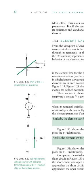
- Page 110: markings inside it, as in Figure 1.
- Page 116: 34 CHAPTER ONE the circuit abstract
- Page 120: 36 CHAPTER ONE the circuit abstract
- Page 124: 38 CHAPTER ONE the circuit abstract
- Page 128: 40 CHAPTER ONE the circuit abstract
- Page 132: 42 CHAPTER ONE the circuit abstract
- Page 136: 44 CHAPTER ONE the circuit abstract
- Page 140: 46 CHAPTER ONE the circuit abstract
- Page 144: 48 CHAPTER ONE the circuit abstract
- Page 148: 50 CHAPTER ONE the circuit abstract
- Page 154: esistive networks 2 A simple electr
- Page 158: Elements A B DA Distributed node Id
- Page 162:
. . . i 1 i 1 i 2 i 2 2.2 Kirchhoff
- Page 166:
Arbitrary Circuit i 1 = 3Acos(ωt)
- Page 170:
vM-1 + v 1 + difference between the
- Page 174:
KVL to the four loops yields - v 1
- Page 178:
+ v 1 - #1 + v2 - + 2 V - #2 #3 #4
- Page 182:
and voltage in the case of a resist
- Page 186:
Finally, following Step 4, we combi
- Page 190:
intuition, it is likely to be much
- Page 194:
energy dissipated by the resistor i
- Page 198:
The voltage-divider relationship in
- Page 202:
is linearly proportional to the vol
- Page 206:
example 2.19 voltage-divider circui
- Page 210:
Finally, Equations 2.76 through 2.8
- Page 214:
esistors in terms of the individual
- Page 218:
defined in Figure 2.46, the constit
- Page 222:
1 R1 2 V + - 4 We now have ten inde
- Page 226:
2.4 Intuitive Method of Circuit Ana
- Page 230:
and v2 = V R2(R3+R4) R2+R3+R4 R1 +
- Page 234:
A (a) B 2.4 Intuitive Method of Cir
- Page 238:
2.5 MORE CIRCUIT EXAMPLES Let us no
- Page 242:
WWW example 2.28 basic circuit anal
- Page 246:
2.6 Dependent Sources and the Contr
- Page 250:
I + vI - R I i I iIN + 2.6 Dependen
- Page 254:
2.6 Dependent Sources and the Contr
- Page 258:
2.6 Dependent Sources and the Contr
- Page 262:
2.7 A Formulation Suitable for a Co
- Page 266:
◮ Conservation of energy is a pow
- Page 270:
+ v − i i A + v A − (a) + v −
- Page 274:
problem 2.6 In each network in Figu
- Page 278:
problem 2.12 Sketch the v i charact
- Page 286:
network theorems 3 3.1 INTRODUCTION
- Page 290:
v 2 V i 1 1 + - 1.5 V a 1 Ω b i0
- Page 294:
a 1 V 1 V d + v4 + v1 - - - v5 + +
- Page 298:
. . . . . . 5 A 2 kΩ 3.3 The Node
- Page 302:
will directly proceed with writing
- Page 306:
i3 =−I. (3.16) This completes the
- Page 310:
determined by standard algebraic me
- Page 314:
KCL at the nodes defined by the nod
- Page 318:
which simplifies to or 5V+ 6V vO =
- Page 322:
which are the individual statements
- Page 326:
To continue the node analysis of th
- Page 330:
in Figure 3.25. In this case, it is
- Page 334:
Next, following Step 4, we solve Eq
- Page 338:
By simplifying Equation 3.62, we ob
- Page 342:
Using the conductance form of the v
- Page 346:
+ V1- I 1 + V -2 + - V 3 The superp
- Page 350:
1 V + - 2 Ω ei 2 Ω 2 Ω ev 2
- Page 354:
using the voltage-divider relation
- Page 358:
1 kΩ v 2 1 100Ω v 1 kΩ 2 2 V
- Page 362:
We can obtain v b2 by using KVL as
- Page 366:
v oc + - 3.6 Thévenin’s Theorem
- Page 370:
+ 2 V - 2 --- 3 Ω FIGURE 3.59 The
- Page 374:
The current I2 can be quickly deter
- Page 378:
1 V 2 Ω + a b I - a′ b′ 3.6 T
- Page 382:
3.6 Thévenin’s Theorem and Norto
- Page 386:
3.6 Thévenin’s Theorem and Norto
- Page 390:
2 cos(ωt) + - 1 kΩ v I = 0 v I 3
- Page 394:
3.6 Thévenin’s Theorem and Norto
- Page 398:
+ - R1 ⋅ R2 ---------------------
- Page 402:
3.7 SUMMARY ◮ In the node method
- Page 406:
1 Ω + v - 1 Ω 1 Ω 3.7 Summary
- Page 410:
exercise 3.17 Find the Thévenin eq
- Page 414:
R 1 I R 4 + R2 R3 v - R5 b) Find th
- Page 418:
problem 3.2 a) Prove, if possible,
- Page 422:
problem 3.9 In Figure 3.138, find v
- Page 426:
source is βI1, where β is some co
- Page 434:
4 analysis of nonlinear circuits Th
- Page 438:
4.1 Introduction to Nonlinear Eleme
- Page 442:
Given the analytical expression for
- Page 446:
Equation 4.9 but not the physical d
- Page 450:
When we reconnect the nonlinear dev
- Page 454:
Given that I = 2 A, we can solve fo
- Page 458:
the application of Thévenin’s Th
- Page 462:
flow, whereas for negative voltages
- Page 466:
segment of operation associated wit
- Page 470:
(a) (b) iD ≥ 0 (c) i D < 0 (d) To
- Page 474:
5 kΩ + vBI - 1mA 1 kΩ 3 kΩ 2
- Page 478:
∆v I = 0.001 V sin(ωt) + - VI =
- Page 482:
We know that the output current is
- Page 486:
and replacing iD by its DC value pl
- Page 490:
which can be interpreted as a linea
- Page 494:
Large signal Small signal + + vD iD
- Page 498:
and ID = KV 2 O = 1 mA. Next, follo
- Page 502:
Next, following the second step of
- Page 506:
4.6 SUMMARY ◮ This chapter introd
- Page 510:
e) Find the incremental change in t
- Page 514:
problem 4.1 Consider the circuit co
- Page 518:
c) What is the Thévenin output res
- Page 522:
) Another crazy device, C, with v i
- Page 526:
FIGURE 4.67 v i + VB - + - i N + v
- Page 534:
the digital abstraction 5 Value dis
- Page 538:
true false 0V 5V 5V 0V 2V 0V 0V 1V
- Page 542:
“1” Sender 5 V V H V L Valid 1
- Page 546:
Sender A = 0 v OUT = 0.5 V Sender A
- Page 550:
5.1 Voltage Levels and the Static D
- Page 554:
5 V 5 V “1” Valid 4.5 V 1 4 V V
- Page 558:
From Equation 5.5, the noise margin
- Page 562:
the ‘‘·’’ symbol as: Z = X
- Page 566:
inputs that fall within valid input
- Page 570:
5.4 Standard Sum-of-Products Repres
- Page 574:
5.5 Simplifying Logic Expressions C
- Page 578:
B B A B C C shown below by applying
- Page 582:
The following sequence of simplific
- Page 586:
a voltage level of 0Vtodenote a log
- Page 590:
= A1A0B1B0 + A1 ¯B1 ¯B0 + A1 Ā0
- Page 594:
A 7 S 7 B 7 C 2 A 1 S 1 B 1 One-bit
- Page 598:
exercise 5.2 Write a boolean expres
- Page 602:
exercise 5.9 Consider a family of l
- Page 606:
A B C D OUT2 OUT1 OUT0 0 0 0 0 0 0
- Page 610:
an NTL inverter operate correctly?
- Page 614:
chapter 6 6.1 THE SWITCH 6.2 LOGIC
- Page 620:
286 CHAPTER SIX the mosfet switch C
- Page 624:
288 CHAPTER SIX the mosfet switch F
- Page 628:
290 CHAPTER SIX the mosfet switch G
- Page 632:
292 CHAPTER SIX the mosfet switch F
- Page 636:
294 CHAPTER SIX the mosfet switch A
- Page 640:
296 CHAPTER SIX the mosfet switch F
- Page 644:
298 CHAPTER SIX the mosfet switch F
- Page 648:
300 CHAPTER SIX the mosfet switch G
- Page 652:
302 CHAPTER SIX the mosfet switch F
- Page 656:
304 CHAPTER SIX the mosfet switch F
- Page 660:
306 CHAPTER SIX the mosfet switch v
- Page 664:
308 CHAPTER SIX the mosfet switch S
- Page 668:
310 CHAPTER SIX the mosfet switch 4
- Page 672:
312 CHAPTER SIX the mosfet switch F
- Page 676:
314 CHAPTER SIX the mosfet switch F
- Page 680:
316 CHAPTER SIX the mosfet switch F
- Page 684:
318 CHAPTER SIX the mosfet switch F
- Page 688:
320 CHAPTER SIX the mosfet switch F
- Page 692:
322 CHAPTER SIX the mosfet switch 6
- Page 696:
324 CHAPTER SIX the mosfet switch A
- Page 700:
326 CHAPTER SIX the mosfet switch V
- Page 706:
chapter 7 7.1 SIGNAL AMPLIFICATION
- Page 712:
332 CHAPTER SEVEN the mosfet amplif
- Page 716:
334 CHAPTER SEVEN the mosfet amplif
- Page 720:
336 CHAPTER SEVEN the mosfet amplif
- Page 724:
338 CHAPTER SEVEN the mosfet amplif
- Page 728:
340 CHAPTER SEVEN the mosfet amplif
- Page 732:
342 CHAPTER SEVEN the mosfet amplif
- Page 736:
344 CHAPTER SEVEN the mosfet amplif
- Page 740:
346 CHAPTER SEVEN the mosfet amplif
- Page 744:
348 CHAPTER SEVEN the mosfet amplif
- Page 748:
350 CHAPTER SEVEN the mosfet amplif
- Page 752:
352 CHAPTER SEVEN the mosfet amplif
- Page 756:
354 CHAPTER SEVEN the mosfet amplif
- Page 760:
356 CHAPTER SEVEN the mosfet amplif
- Page 764:
358 CHAPTER SEVEN the mosfet amplif
- Page 768:
360 CHAPTER SEVEN the mosfet amplif
- Page 772:
362 CHAPTER SEVEN the mosfet amplif
- Page 776:
364 CHAPTER SEVEN the mosfet amplif
- Page 780:
366 CHAPTER SEVEN the mosfet amplif
- Page 784:
368 CHAPTER SEVEN the mosfet amplif
- Page 788:
370 CHAPTER SEVEN the mosfet amplif
- Page 792:
372 CHAPTER SEVEN the mosfet amplif
- Page 796:
374 CHAPTER SEVEN the mosfet amplif
- Page 800:
376 CHAPTER SEVEN the mosfet amplif
- Page 804:
378 CHAPTER SEVEN the mosfet amplif
- Page 808:
380 CHAPTER SEVEN the mosfet amplif
- Page 812:
382 CHAPTER SEVEN the mosfet amplif
- Page 816:
384 CHAPTER SEVEN the mosfet amplif
- Page 820:
386 CHAPTER SEVEN the mosfet amplif
- Page 824:
388 CHAPTER SEVEN the mosfet amplif
- Page 828:
390 CHAPTER SEVEN the mosfet amplif
- Page 832:
392 CHAPTER SEVEN the mosfet amplif
- Page 836:
394 CHAPTER SEVEN the mosfet amplif
- Page 840:
396 CHAPTER SEVEN the mosfet amplif
- Page 844:
398 CHAPTER SEVEN the mosfet amplif
- Page 848:
400 CHAPTER SEVEN the mosfet amplif
- Page 852:
402 CHAPTER SEVEN the mosfet amplif
- Page 858:
the small-signal model 8 8.1 OVERVI
- Page 862:
v i V I + - + - v O V S V T V S R L
- Page 866:
Our goal is to use the Taylor serie
- Page 870:
From Equation 8.1 we know that 8.2
- Page 874:
A systematic procedure for finding
- Page 878:
4. Complete the small-signal analys
- Page 882:
example 8.1 a mosfet with its gate
- Page 886:
The output operating current ID is
- Page 890:
|Gain| 20 10 V T = 1 V sense, since
- Page 894:
suppose the first stage is biased a
- Page 898:
v i = 0 i d = K(V I - V T )v i = 0
- Page 902:
Equation 8.35, we get an expression
- Page 906:
We can now derive the change in the
- Page 910:
where AD is called the difference-m
- Page 914:
+ v x - R L gm ----- ⋅ v 2 d v s
- Page 918:
From the Thévenin equivalent circu
- Page 922:
+ - vgs i ds = g m v gs i s When gm
- Page 926:
the BJT operates in its active regi
- Page 930:
linearized equivalents, and in whic
- Page 934:
Dividing throughout by i test and s
- Page 938:
where the large-signal bias conditi
- Page 942:
8.3 SUMMARY ◮ This chapter expand
- Page 946:
) Assuming we desire to use voltage
- Page 950:
f) Again assume that VT = 1V,K = 2
- Page 954:
e) Determine the small-signal outpu
- Page 958:
chapter 9 9.1 CONSTITUTIVE LAWS 9.2
- Page 964:
458 CHAPTER NINE energy storage ele
- Page 968:
460 CHAPTER NINE energy storage ele
- Page 972:
462 CHAPTER NINE energy storage ele
- Page 976:
464 CHAPTER NINE energy storage ele
- Page 980:
466 CHAPTER NINE energy storage ele
- Page 984:
468 CHAPTER NINE energy storage ele
- Page 988:
470 CHAPTER NINE energy storage ele
- Page 992:
472 CHAPTER NINE energy storage ele
- Page 996:
474 CHAPTER NINE energy storage ele
- Page 1000:
476 CHAPTER NINE energy storage ele
- Page 1004:
478 CHAPTER NINE energy storage ele
- Page 1008:
480 CHAPTER NINE energy storage ele
- Page 1012:
482 CHAPTER NINE energy storage ele
- Page 1016:
484 CHAPTER NINE energy storage ele
- Page 1020:
486 CHAPTER NINE energy storage ele
- Page 1024:
488 CHAPTER NINE energy storage ele
- Page 1028:
490 CHAPTER NINE energy storage ele
- Page 1032:
492 CHAPTER NINE energy storage ele
- Page 1036:
494 CHAPTER NINE energy storage ele
- Page 1040:
496 CHAPTER NINE energy storage ele
- Page 1044:
498 CHAPTER NINE energy storage ele
- Page 1050:
chapter 10 10.1 ANALYSIS OF RC CIRC
- Page 1056:
504 CHAPTER TEN first-order transie
- Page 1060:
506 CHAPTER TEN first-order transie
- Page 1064:
508 CHAPTER TEN first-order transie
- Page 1068:
510 CHAPTER TEN first-order transie
- Page 1072:
512 CHAPTER TEN first-order transie
- Page 1076:
514 CHAPTER TEN first-order transie
- Page 1080:
516 CHAPTER TEN first-order transie
- Page 1084:
518 CHAPTER TEN first-order transie
- Page 1088:
520 CHAPTER TEN first-order transie
- Page 1092:
522 CHAPTER TEN first-order transie
- Page 1096:
524 CHAPTER TEN first-order transie
- Page 1100:
526 CHAPTER TEN first-order transie
- Page 1104:
528 CHAPTER TEN first-order transie
- Page 1108:
530 CHAPTER TEN first-order transie
- Page 1112:
532 CHAPTER TEN first-order transie
- Page 1116:
534 CHAPTER TEN first-order transie
- Page 1120:
536 CHAPTER TEN first-order transie
- Page 1124:
538 CHAPTER TEN first-order transie
- Page 1128:
540 CHAPTER TEN first-order transie
- Page 1132:
542 CHAPTER TEN first-order transie
- Page 1136:
544 CHAPTER TEN first-order transie
- Page 1140:
546 CHAPTER TEN first-order transie
- Page 1144:
548 CHAPTER TEN first-order transie
- Page 1148:
550 CHAPTER TEN first-order transie
- Page 1152:
552 CHAPTER TEN first-order transie
- Page 1156:
554 CHAPTER TEN first-order transie
- Page 1160:
556 CHAPTER TEN first-order transie
- Page 1164:
558 CHAPTER TEN first-order transie
- Page 1168:
560 CHAPTER TEN first-order transie
- Page 1172:
562 CHAPTER TEN first-order transie
- Page 1176:
564 CHAPTER TEN first-order transie
- Page 1180:
566 CHAPTER TEN first-order transie
- Page 1184:
568 CHAPTER TEN first-order transie
- Page 1188:
570 CHAPTER TEN first-order transie
- Page 1192:
572 CHAPTER TEN first-order transie
- Page 1196:
574 CHAPTER TEN first-order transie
- Page 1200:
576 CHAPTER TEN first-order transie
- Page 1204:
578 CHAPTER TEN first-order transie
- Page 1208:
580 CHAPTER TEN first-order transie
- Page 1212:
582 CHAPTER TEN first-order transie
- Page 1216:
584 CHAPTER TEN first-order transie
- Page 1220:
586 CHAPTER TEN first-order transie
- Page 1224:
588 CHAPTER TEN first-order transie
- Page 1228:
590 CHAPTER TEN first-order transie
- Page 1232:
592 CHAPTER TEN first-order transie
- Page 1238:
11 energy and power in digital circ
- Page 1242:
What is the amount of energy stored
- Page 1246:
+ V - R 1 v C FIGURE 11.3 Equivalen
- Page 1250:
Separating the terms containing a T
- Page 1254:
11.2.3 TOTAL ENERGY DISSIPATED Comb
- Page 1258:
11.3 Power Dissipation in Logic Gat
- Page 1262:
transitions from low to high): vC =
- Page 1266:
Simplifying and rearranging, we get
- Page 1270:
11.4 NMOS LOGIC The pullup device t
- Page 1274:
v IN T/2 FIGURE 11.19 CMOS inverter
- Page 1278:
v IN i T interval (for example, whe
- Page 1282:
11.5 CMOS Logic CHAPTER ELEVEN 617
- Page 1286:
c) Determine the static power and t
- Page 1290:
e) What is the amount of energy con
- Page 1294:
chapter 12 12.1 UNDRIVEN LC CIRCUIT
- Page 1300:
626 CHAPTER TWELVE transients in se
- Page 1304:
628 CHAPTER TWELVE transients in se
- Page 1308:
630 CHAPTER TWELVE transients in se
- Page 1312:
632 CHAPTER TWELVE transients in se
- Page 1316:
634 CHAPTER TWELVE transients in se
- Page 1320:
636 CHAPTER TWELVE transients in se
- Page 1324:
638 CHAPTER TWELVE transients in se
- Page 1328:
640 CHAPTER TWELVE transients in se
- Page 1332:
642 CHAPTER TWELVE transients in se
- Page 1336:
644 CHAPTER TWELVE transients in se
- Page 1340:
646 CHAPTER TWELVE transients in se
- Page 1344:
648 CHAPTER TWELVE transients in se
- Page 1348:
650 CHAPTER TWELVE transients in se
- Page 1352:
652 CHAPTER TWELVE transients in se
- Page 1356:
654 CHAPTER TWELVE transients in se
- Page 1360:
656 CHAPTER TWELVE transients in se
- Page 1364:
658 CHAPTER TWELVE transients in se
- Page 1368:
660 CHAPTER TWELVE transients in se
- Page 1372:
662 CHAPTER TWELVE transients in se
- Page 1376:
664 CHAPTER TWELVE transients in se
- Page 1380:
666 CHAPTER TWELVE transients in se
- Page 1384:
668 CHAPTER TWELVE transients in se
- Page 1388:
670 CHAPTER TWELVE transients in se
- Page 1392:
672 CHAPTER TWELVE transients in se
- Page 1396:
674 CHAPTER TWELVE transients in se
- Page 1400:
676 CHAPTER TWELVE transients in se
- Page 1404:
678 CHAPTER TWELVE transients in se
- Page 1408:
680 CHAPTER TWELVE transients in se
- Page 1412:
682 CHAPTER TWELVE transients in se
- Page 1416:
684 CHAPTER TWELVE transients in se
- Page 1420:
686 CHAPTER TWELVE transients in se
- Page 1424:
688 CHAPTER TWELVE transients in se
- Page 1428:
690 CHAPTER TWELVE transients in se
- Page 1432:
692 CHAPTER TWELVE transients in se
- Page 1436:
694 CHAPTER TWELVE transients in se
- Page 1440:
696 CHAPTER TWELVE transients in se
- Page 1444:
698 CHAPTER TWELVE transients in se
- Page 1450:
chapter 13 13.1 INTRODUCTION 13.2 A
- Page 1456:
704 CHAPTER THIRTEEN sinusoidal ste
- Page 1460:
706 CHAPTER THIRTEEN sinusoidal ste
- Page 1464:
708 CHAPTER THIRTEEN sinusoidal ste
- Page 1468:
710 CHAPTER THIRTEEN sinusoidal ste
- Page 1472:
712 CHAPTER THIRTEEN sinusoidal ste
- Page 1476:
714 CHAPTER THIRTEEN sinusoidal ste
- Page 1480:
716 CHAPTER THIRTEEN sinusoidal ste
- Page 1484:
718 CHAPTER THIRTEEN sinusoidal ste
- Page 1488:
720 CHAPTER THIRTEEN sinusoidal ste
- Page 1492:
722 CHAPTER THIRTEEN sinusoidal ste
- Page 1496:
724 CHAPTER THIRTEEN sinusoidal ste
- Page 1500:
726 CHAPTER THIRTEEN sinusoidal ste
- Page 1504:
728 CHAPTER THIRTEEN sinusoidal ste
- Page 1508:
730 CHAPTER THIRTEEN sinusoidal ste
- Page 1512:
732 CHAPTER THIRTEEN sinusoidal ste
- Page 1516:
734 CHAPTER THIRTEEN sinusoidal ste
- Page 1520:
736 CHAPTER THIRTEEN sinusoidal ste
- Page 1524:
738 CHAPTER THIRTEEN sinusoidal ste
- Page 1528:
740 CHAPTER THIRTEEN sinusoidal ste
- Page 1532:
742 CHAPTER THIRTEEN sinusoidal ste
- Page 1536:
744 CHAPTER THIRTEEN sinusoidal ste
- Page 1540:
746 CHAPTER THIRTEEN sinusoidal ste
- Page 1544:
748 CHAPTER THIRTEEN sinusoidal ste
- Page 1548:
750 CHAPTER THIRTEEN sinusoidal ste
- Page 1552:
752 CHAPTER THIRTEEN sinusoidal ste
- Page 1556:
754 CHAPTER THIRTEEN sinusoidal ste
- Page 1560:
756 CHAPTER THIRTEEN sinusoidal ste
- Page 1564:
758 CHAPTER THIRTEEN sinusoidal ste
- Page 1568:
760 CHAPTER THIRTEEN sinusoidal ste
- Page 1572:
762 CHAPTER THIRTEEN sinusoidal ste
- Page 1576:
764 CHAPTER THIRTEEN sinusoidal ste
- Page 1580:
766 CHAPTER THIRTEEN sinusoidal ste
- Page 1584:
768 CHAPTER THIRTEEN sinusoidal ste
- Page 1588:
770 CHAPTER THIRTEEN sinusoidal ste
- Page 1592:
772 CHAPTER THIRTEEN sinusoidal ste
- Page 1596:
774 CHAPTER THIRTEEN sinusoidal ste
- Page 1602:
sinusoidal steady state: resonance
- Page 1606:
Assuming a homogeneous solution of
- Page 1610:
14.1 Parallel RLC, Sinusoidal Respo
- Page 1614:
Amplitude of v(t) (V) Amplitude of
- Page 1618:
|H| 10 1 10 0 10 -1 10 -2 R = 4 14.
- Page 1622:
14.2 Frequency Response for Resonan
- Page 1626:
R R/10 R/100 V p ⁄ I o (Ω) 0.70
- Page 1630:
The transfer function is given by o
- Page 1634:
14.2 Frequency Response for Resonan
- Page 1638:
14.2 Frequency Response for Resonan
- Page 1642:
R/10 R/100 V p ⁄ I o R (Ω) 0.01
- Page 1646:
|H c | 10 7.07 1 10 0 10 -1 ω 0.70
- Page 1650:
14.3 SERIES RLC A second topology f
- Page 1654:
Multiplying the numerator and denom
- Page 1658:
For the parameters given in Figure
- Page 1662:
|H|
- Page 1666:
s/L = s2 + 2αs + ω2 . (14.73) o W
- Page 1670:
|H r | |H c | 10 0 10 -1 10 4 10 -2
- Page 1674:
This tells us that the magnitude of
- Page 1678:
|H l | 10 2 10 1 10 0 10 -1 10 -2
- Page 1682:
V l = jωoLI = jVi ωoL 14.6 Store
- Page 1686:
14.6 Stored Energy in a Resonant Ci
- Page 1690:
14.7 SUMMARY ◮ Resonant systems a
- Page 1694:
◮ Other equivalent definitions fo
- Page 1698:
v I (t) + - FIGURE 14.47 i I (t) i
- Page 1702:
i(t) R FIGURE 14.55 L C + - v(t) 14
- Page 1706:
) Now suppose that vS = VS cos(ωt)
- Page 1710:
i S (t) + - + C - v C L R = 100 Ω
- Page 1714:
c) The customer is now very happy.
- Page 1718:
chapter 15 15.1 INTRODUCTION 15.2 D
- Page 1724:
838 CHAPTER FIFTEEN the operational
- Page 1728:
840 CHAPTER FIFTEEN the operational
- Page 1732:
842 CHAPTER FIFTEEN the operational
- Page 1736:
844 CHAPTER FIFTEEN the operational
- Page 1740:
846 CHAPTER FIFTEEN the operational
- Page 1744:
848 CHAPTER FIFTEEN the operational
- Page 1748:
850 CHAPTER FIFTEEN the operational
- Page 1752:
852 CHAPTER FIFTEEN the operational
- Page 1756:
854 CHAPTER FIFTEEN the operational
- Page 1760:
856 CHAPTER FIFTEEN the operational
- Page 1764:
858 CHAPTER FIFTEEN the operational
- Page 1768:
860 CHAPTER FIFTEEN the operational
- Page 1772:
862 CHAPTER FIFTEEN the operational
- Page 1776:
864 CHAPTER FIFTEEN the operational
- Page 1780:
866 CHAPTER FIFTEEN the operational
- Page 1784:
868 CHAPTER FIFTEEN the operational
- Page 1788:
870 CHAPTER FIFTEEN the operational
- Page 1792:
872 CHAPTER FIFTEEN the operational
- Page 1796:
874 CHAPTER FIFTEEN the operational
- Page 1800:
876 CHAPTER FIFTEEN the operational
- Page 1804:
878 CHAPTER FIFTEEN the operational
- Page 1808:
880 CHAPTER FIFTEEN the operational
- Page 1812:
882 CHAPTER FIFTEEN the operational
- Page 1816:
884 CHAPTER FIFTEEN the operational
- Page 1820:
886 CHAPTER FIFTEEN the operational
- Page 1824:
888 CHAPTER FIFTEEN the operational
- Page 1828:
890 CHAPTER FIFTEEN the operational
- Page 1832:
892 CHAPTER FIFTEEN the operational
- Page 1836:
894 CHAPTER FIFTEEN the operational
- Page 1840:
896 CHAPTER FIFTEEN the operational
- Page 1844:
898 CHAPTER FIFTEEN the operational
- Page 1848:
900 CHAPTER FIFTEEN the operational
- Page 1852:
902 CHAPTER FIFTEEN the operational
- Page 1858:
diodes 16 16.1 INTRODUCTION The dio
- Page 1862:
10 pA i D v D 16.2 Semiconductor Di
- Page 1866:
where the diode current iD is zero
- Page 1870:
+ - (a) Circuit 0.6 V + - Rd R + v
- Page 1874:
16.4 Nonlinear Analysis with RL and
- Page 1878:
16.4 Nonlinear Analysis with RL and
- Page 1882:
+10 0 -10 v i (V) Hence the circuit
- Page 1886:
16.6 SUMMARY ◮ The following is a
- Page 1890:
problem 16.1 For the two circuits s
- Page 1894:
voltages 10 V 0 -10 V Diode ON Diod
- Page 1902:
appendix a maxwell’s equations an
- Page 1906:
The preceding equation says that in
- Page 1910:
x y S x S y Closed surface envelopi
- Page 1914:
the point-mass simplification, in w
- Page 1918:
d + V - + v 3 - a +v1- b c +v 4 - F
- Page 1922:
A.3 Deriving the Resistance of a Pi
- Page 1930:
appendix b trigonometric functions
- Page 1934:
B.4 PRODUCTS cos(θ1) cos(θ2) = 1
- Page 1938:
appendix c C.1 MAGNITUDE AND PHASE
- Page 1944:
948 APPENDIX C complex numbers C.2
- Page 1948:
950 APPENDIX C complex numbers For
- Page 1952:
952 APPENDIX C complex numbers Here
- Page 1958:
appendix d
- Page 1964:
958 APPENDIX D solving simultaneous
- Page 1968:
960 answers to selected problems Ex
- Page 1972:
962 answers to selected problems Pr
- Page 1976:
964 answers to selected problems ch
- Page 1980:
966 answers to selected problems Pr
- Page 1984:
968 answers to selected problems Ex
- Page 1990:
figure acknowledgements Figure 1.18
- Page 1996:
974 INDEX Cartesian-to-polar coordi
- Page 2000:
976 INDEX energy storage elements,
- Page 2004:
978 INDEX lightbulb circuit, 5 8 Li
- Page 2008:
980 INDEX OR function, 257, 261 OR
- Page 2012:
982 INDEX Siemens, 31, 48 signal cl
- Page 2016:
984 INDEX under-compensation, 753 7