- Page 2:
In Praise of Foundations of Analog
- Page 8:
about the authors Anant Agarwal is
- Page 12:
Publisher: Denise E. M. Penrose Pub
- Page 18:
contents Material marked with WWW a
- Page 22:
5.6 Number Representation .........
- Page 26:
10.5 State and State Variables ....
- Page 30:
13.6 Time Domain versus Frequency D
- Page 34:
A.1.2 The Second Constraint of the
- Page 40:
xx PREFACE treat networks of passiv
- Page 44:
xxii PREFACE Chapter 5 introduces t
- Page 48:
xxiv PREFACE ◮ Labs. A collection
- Page 54:
the circuit abstraction 1‘‘Engi
- Page 58:
Physics Computer Circuits and archi
- Page 62:
analogous to the point mass simplif
- Page 66:
ook from the broad perspective of a
- Page 70:
elation between the terminal curren
- Page 74:
1.4 Limitations of the Lumped Circu
- Page 78:
seriously affect the circuit behavi
- Page 82:
1.5 Practical Two-Terminal Elements
- Page 86:
Area a l 1.5 Practical Two-Terminal
- Page 90:
with unit length and width, show th
- Page 94:
signal values are derived as a func
- Page 98:
However, as introduced in Chapter 9
- Page 102:
Now, suppose the 3 V battery is con
- Page 106:
Thus the power delivered by the bat
- Page 110:
markings inside it, as in Figure 1.
- Page 114:
example 1.17 more on terminal varia
- Page 118:
Before proceeding further, it is im
- Page 122:
V(t) + - + V - R m (a) R + v t - 1.
- Page 126:
p max i p max 1.7 Modeling Physical
- Page 130:
and our familiar lightbulb circuit
- Page 134:
a battery, wires, and a lightbulb.
- Page 138:
Native and Non-Native Signal Repres
- Page 142:
◮ The amount of energy w(t) consu
- Page 146:
exercise 1.2 a) The battery on your
- Page 150:
chapter 2 2.1 TERMINOLOGY 2.2 KIRCH
- Page 156:
54 CHAPTER TWO resistive networks F
- Page 160:
56 CHAPTER TWO resistive networks d
- Page 164:
58 CHAPTER TWO resistive networks i
- Page 168:
60 CHAPTER TWO resistive networks 1
- Page 172:
62 CHAPTER TWO resistive networks F
- Page 176:
64 CHAPTER TWO resistive networks 1
- Page 180:
66 CHAPTER TWO resistive networks T
- Page 184:
68 CHAPTER TWO resistive networks +
- Page 188:
70 CHAPTER TWO resistive networks e
- Page 192:
72 CHAPTER TWO resistive networks i
- Page 196:
74 CHAPTER TWO resistive networks v
- Page 200:
76 CHAPTER TWO resistive networks R
- Page 204:
78 CHAPTER TWO resistive networks F
- Page 208:
80 CHAPTER TWO resistive networks I
- Page 212:
82 CHAPTER TWO resistive networks R
- Page 216:
84 CHAPTER TWO resistive networks 2
- Page 220:
86 CHAPTER TWO resistive networks F
- Page 224:
88 CHAPTER TWO resistive networks F
- Page 228:
90 CHAPTER TWO resistive networks i
- Page 232:
92 CHAPTER TWO resistive networks F
- Page 236:
94 CHAPTER TWO resistive networks F
- Page 240:
96 CHAPTER TWO resistive networks i
- Page 244:
98 CHAPTER TWO resistive networks F
- Page 248:
100 CHAPTER TWO resistive networks
- Page 252:
102 CHAPTER TWO resistive networks
- Page 256:
104 CHAPTER TWO resistive networks
- Page 260:
106 CHAPTER TWO resistive networks
- Page 264:
108 CHAPTER TWO resistive networks
- Page 268:
110 CHAPTER TWO resistive networks
- Page 272:
112 CHAPTER TWO resistive networks
- Page 276:
114 CHAPTER TWO resistive networks
- Page 282:
chapter 3 3.1 INTRODUCTION 3.2 THE
- Page 288:
120 CHAPTER THREE network theorems
- Page 292:
122 CHAPTER THREE network theorems
- Page 296:
124 CHAPTER THREE network theorems
- Page 300:
126 CHAPTER THREE network theorems
- Page 304:
128 CHAPTER THREE network theorems
- Page 308:
130 CHAPTER THREE network theorems
- Page 312:
132 CHAPTER THREE network theorems
- Page 316:
134 CHAPTER THREE network theorems
- Page 320:
136 CHAPTER THREE network theorems
- Page 324:
138 CHAPTER THREE network theorems
- Page 328:
140 CHAPTER THREE network theorems
- Page 332:
142 CHAPTER THREE network theorems
- Page 336:
144 CHAPTER THREE network theorems
- Page 340:
146 CHAPTER THREE network theorems
- Page 344:
148 CHAPTER THREE network theorems
- Page 348:
150 CHAPTER THREE network theorems
- Page 352:
152 CHAPTER THREE network theorems
- Page 356:
154 CHAPTER THREE network theorems
- Page 360:
156 CHAPTER THREE network theorems
- Page 364:
158 CHAPTER THREE network theorems
- Page 368:
160 CHAPTER THREE network theorems
- Page 372:
162 CHAPTER THREE network theorems
- Page 376:
164 CHAPTER THREE network theorems
- Page 380:
166 CHAPTER THREE network theorems
- Page 384:
168 CHAPTER THREE network theorems
- Page 388:
170 CHAPTER THREE network theorems
- Page 392:
172 CHAPTER THREE network theorems
- Page 396:
174 CHAPTER THREE network theorems
- Page 400:
176 CHAPTER THREE network theorems
- Page 404:
178 CHAPTER THREE network theorems
- Page 408:
180 CHAPTER THREE network theorems
- Page 412:
182 CHAPTER THREE network theorems
- Page 416:
184 CHAPTER THREE network theorems
- Page 420:
186 CHAPTER THREE network theorems
- Page 424:
188 CHAPTER THREE network theorems
- Page 430:
chapter 4 4.1 INTRODUCTION TO NONLI
- Page 436:
194 CHAPTER FOUR analysis of nonlin
- Page 440:
196 CHAPTER FOUR analysis of nonlin
- Page 444:
198 CHAPTER FOUR analysis of nonlin
- Page 448:
(a) + V - R2 I0 R3 i3 (c) + V - R 1
- Page 452:
202 CHAPTER FOUR analysis of nonlin
- Page 456:
204 CHAPTER FOUR analysis of nonlin
- Page 460:
206 CHAPTER FOUR analysis of nonlin
- Page 464:
208 CHAPTER FOUR analysis of nonlin
- Page 468:
210 CHAPTER FOUR analysis of nonlin
- Page 472:
212 CHAPTER FOUR analysis of nonlin
- Page 476:
214 CHAPTER FOUR analysis of nonlin
- Page 480:
216 CHAPTER FOUR analysis of nonlin
- Page 484:
218 CHAPTER FOUR analysis of nonlin
- Page 488:
220 CHAPTER FOUR analysis of nonlin
- Page 492:
222 CHAPTER FOUR analysis of nonlin
- Page 496:
224 CHAPTER FOUR analysis of nonlin
- Page 500:
226 CHAPTER FOUR analysis of nonlin
- Page 504:
228 CHAPTER FOUR analysis of nonlin
- Page 508:
230 CHAPTER FOUR analysis of nonlin
- Page 512:
232 CHAPTER FOUR analysis of nonlin
- Page 516:
234 CHAPTER FOUR analysis of nonlin
- Page 520:
236 CHAPTER FOUR analysis of nonlin
- Page 524:
238 CHAPTER FOUR analysis of nonlin
- Page 530:
chapter 5 5.1 VOLTAGE LEVELS AND TH
- Page 536:
244 CHAPTER FIVE the digital abstra
- Page 540:
246 CHAPTER FIVE the digital abstra
- Page 544:
248 CHAPTER FIVE the digital abstra
- Page 548:
250 CHAPTER FIVE the digital abstra
- Page 552:
252 CHAPTER FIVE the digital abstra
- Page 556:
254 CHAPTER FIVE the digital abstra
- Page 560:
256 CHAPTER FIVE the digital abstra
- Page 564:
258 CHAPTER FIVE the digital abstra
- Page 568:
260 CHAPTER FIVE the digital abstra
- Page 572:
262 CHAPTER FIVE the digital abstra
- Page 576:
264 CHAPTER FIVE the digital abstra
- Page 580:
266 CHAPTER FIVE the digital abstra
- Page 584:
268 CHAPTER FIVE the digital abstra
- Page 588:
270 CHAPTER FIVE the digital abstra
- Page 592:
272 CHAPTER FIVE the digital abstra
- Page 596:
274 CHAPTER FIVE the digital abstra
- Page 600:
276 CHAPTER FIVE the digital abstra
- Page 604:
278 CHAPTER FIVE the digital abstra
- Page 608:
280 CHAPTER FIVE the digital abstra
- Page 612:
282 CHAPTER FIVE the digital abstra
- Page 618:
the mosfet switch 6 This chapter in
- Page 622:
i S + v - + V - Control = “0” C
- Page 626:
6.3 The MOSFET Device and Its S Mod
- Page 630:
6.4 MOSFET Switch Implementation of
- Page 634:
6.4 MOSFET Switch Implementation of
- Page 638:
A B 6.4 MOSFET Switch Implementatio
- Page 642:
Input Output 5 V 4 V 3 V Valid 1 VI
- Page 646:
VIL: For our static discipline, VIL
- Page 650:
i DS Triode region i DS 1 ------- =
- Page 654:
n + n + S L Gate Gate oxide p subst
- Page 658:
6.7 Physical Structure of the MOSFE
- Page 662:
6.8 Static Analysis Using the SR Mo
- Page 666:
v OUT 5V V OH = 4.5 V VOL = 0.5 V 0
- Page 670:
For VS = 5 V and RL = 14 k, we have
- Page 674:
6.8 Static Analysis Using the SR Mo
- Page 678:
I Noise 0.6 V Send 0 Receive 0 v O
- Page 682:
6.9 Signal Restoration, Gain, and N
- Page 686:
v O V OH V OL Slope < 1 V IL 6.9 Si
- Page 690:
6.11 Active Pullups CHAPTER SIX 321
- Page 694:
c) Does the inverter satisfy the st
- Page 698:
problem 6.3 Consider a family of lo
- Page 702:
c) If for each MOSFET, Ron = 500 ,
- Page 710:
the mosfet amplifier 7 7.1 SIGNAL A
- Page 714:
Control port + v IN - i IN = 0 i OU
- Page 718:
Thus, the dependent source provides
- Page 722:
i DS 0 Triode region For v GS ≥ V
- Page 726:
i DS 0 ------------ 1 RON Triode re
- Page 730:
G D S G v GS < V T 7.4 The Switch-C
- Page 734:
7.4 The Switch-Current Source (SCS)
- Page 738:
and vO ≥ vIN − VT. In saturatio
- Page 742:
amplifier transfer function. But be
- Page 746:
Since vGS = vIN = 2.5 V, and VT = 0
- Page 750:
t v O V S 0 t Contrast the amplifie
- Page 754:
7.6 Large-Signal Analysis of the MO
- Page 758:
V S ----- RL iDS i DSi K 2 ---v 2 D
- Page 762:
7.6 Large-Signal Analysis of the MO
- Page 766:
Solving for vIN − VT, weget In ot
- Page 770:
i DS 0.5 mA 0 (0.9 V, 0.41 mA) 7.6
- Page 774:
7.6 Large-Signal Analysis of the MO
- Page 778:
Among other things, the limits dete
- Page 782:
i DS 0.5 mA 0.41 mA 0.1 mA 0 mA v O
- Page 786:
vIN{ v A V B + - + - 1 kΩ G D S V
- Page 790:
i C (mA) Saturation region 0.2 V Ac
- Page 794:
egion, the dependent current source
- Page 798:
As a final thought, although our pi
- Page 802:
Next, substituting RI = 100 k, RL =
- Page 806:
and iB = 0 are the input parameters
- Page 810:
is to find the input operating poin
- Page 814:
Finally, at the output of the ampli
- Page 818:
V S V S + - + - v IN1 + - R 1 M1 M2
- Page 822:
7.8 Switch Unified (SU) MOSFET Mode
- Page 826:
7.9 SUMMARY ◮ The last two chapte
- Page 830:
a) Determine vO in terms of vI if i
- Page 834:
MOSFET is now characterized by the
- Page 838:
problem 7.2 An inverting MOSFET amp
- Page 842:
a large-signal analysis of this cir
- Page 846:
problem 7.9 Consider the current mi
- Page 850:
v I FIGURE 7.86 v I R 1 FIGURE 7.88
- Page 854:
chapter 8 8.1 OVERVIEW OF THE NONLI
- Page 860:
406 CHAPTER EIGHT the small-signal
- Page 864:
408 CHAPTER EIGHT the small-signal
- Page 868:
410 CHAPTER EIGHT the small-signal
- Page 872:
412 CHAPTER EIGHT the small-signal
- Page 876:
414 CHAPTER EIGHT the small-signal
- Page 880:
416 CHAPTER EIGHT the small-signal
- Page 884:
418 CHAPTER EIGHT the small-signal
- Page 888:
420 CHAPTER EIGHT the small-signal
- Page 892:
422 CHAPTER EIGHT the small-signal
- Page 896:
424 CHAPTER EIGHT the small-signal
- Page 900:
426 CHAPTER EIGHT the small-signal
- Page 904:
428 CHAPTER EIGHT the small-signal
- Page 908:
430 CHAPTER EIGHT the small-signal
- Page 912:
432 CHAPTER EIGHT the small-signal
- Page 916:
434 CHAPTER EIGHT the small-signal
- Page 920:
436 CHAPTER EIGHT the small-signal
- Page 924:
438 CHAPTER EIGHT the small-signal
- Page 928:
440 CHAPTER EIGHT the small-signal
- Page 932:
442 CHAPTER EIGHT the small-signal
- Page 936:
444 CHAPTER EIGHT the small-signal
- Page 940:
446 CHAPTER EIGHT the small-signal
- Page 944:
448 CHAPTER EIGHT the small-signal
- Page 948:
450 CHAPTER EIGHT the small-signal
- Page 952:
452 CHAPTER EIGHT the small-signal
- Page 956:
454 CHAPTER EIGHT the small-signal
- Page 962:
energy storage elements 9 To this p
- Page 966:
Reality now presents us with a dile
- Page 970:
9.1 CONSTITUTIVE LAWS In this secti
- Page 974:
In contrast to the resistor, which
- Page 978:
Thus, we see that v(t1) also memori
- Page 982:
the element is negligible. Thus the
- Page 986:
consider rewriting Equation 9.29 as
- Page 990:
9.2.1 CAPACITORS Consider first the
- Page 994:
Next, using KCL we observe that i(t
- Page 998:
of the MOSFET when viewed from the
- Page 1002:
example 9.6 inductance of a wiring
- Page 1006:
+ v 1 - i 1 N1 : N2 FIGURE 9.29 The
- Page 1010:
oth elements is known. Next, follow
- Page 1014:
The behavior seen in Figure 9.37 al
- Page 1018:
-- - 1 T δ(t; T ) 0 T FIGURE 9.43
- Page 1022:
in Figure 9.47a): 0 I(t) = I◦ t
- Page 1026:
9.5 Energy, Charge, and Flux Conser
- Page 1030:
9.5 Energy, Charge, and Flux Conser
- Page 1034:
◮ The corresponding experiment on
- Page 1038:
1 µF 1 µF (a) 1 µF 1 µH (b) 10
- Page 1042:
problem 9.5 A constant voltage sour
- Page 1046:
to determine i1 and i2, again in te
- Page 1054:
first-order transients in linear el
- Page 1058:
v 1 + - R 1 i 1 i R 2 R 3 circuit c
- Page 1062:
We assume a solution of the form vC
- Page 1066:
or 0 v C Small RC Large RC vC = I0R
- Page 1070:
In general, for a resistor and capa
- Page 1074:
The differential equation can be fo
- Page 1078:
These waveforms are shown in Figure
- Page 1082:
It is clear from Equation 10.42 or
- Page 1086:
Hence For nonzero A (A = 0 is a tri
- Page 1090:
(a) Circuit (b) t 0 t » 0 + R t =0
- Page 1094:
satisfy KVL, the capacitor voltage
- Page 1098:
V 0 v S Initial 0 0 i L t v S (t) 1
- Page 1102:
10.4 Propagation Delay and the Digi
- Page 1106:
10.4 Propagation Delay and the Digi
- Page 1110:
10.4 Propagation Delay and the Digi
- Page 1114:
Using the node method, we obtain, v
- Page 1118:
10.4 Propagation Delay and the Digi
- Page 1122:
+ VS - R L R ON 10.4 Propagation De
- Page 1126:
greater than t1 is q(t2) = t1 −
- Page 1130:
(a) + (2) (1) V 1 V2 - + - R C + v
- Page 1134:
+ V1 - (a) (2) (1) R term is the re
- Page 1138:
10.6 ADDITIONAL EXAMPLES 10.6.1 EFF
- Page 1142:
v I + - v C A 0 v C 0 v C 0 R C (a)
- Page 1146:
V 0 + S 1 RC V 0 0 -S 1 RC v C Form
- Page 1150:
V p v I 0 V p 0 v I t p t p v I V p
- Page 1154:
The important feature of this equat
- Page 1158:
0 1 1 1 0 1 Digital circuit 1 clk c
- Page 1162:
R wire CLOCK C GS1 C GS2 C GSn CLOC
- Page 1166:
From KVL around the loop, vI = iLR
- Page 1170:
then the current reduces to iL V s
- Page 1174:
e read as the output dOUT. If no ne
- Page 1178:
The waveforms shown in Figure 10.50
- Page 1182:
see Equation 10.26). When a capacit
- Page 1186:
of the system to the initial stored
- Page 1190:
exercise 10.14 Find the time consta
- Page 1194:
(a) (b) (c) v S (t) v S (t) v S (t)
- Page 1198:
R vI + − C FIGURE 10.88 Find the
- Page 1202:
(a) BUF INV1 INV2 INV3 (b) BUF INV3
- Page 1206:
v INA FIGURE 10.98 C GSA V S R L v
- Page 1210:
problem 10.7 Figure 10.104 shows a
- Page 1214:
i(t) + v - FIGURE 10.108 Box i (A)
- Page 1218:
problem 10.14 State variables can b
- Page 1222:
VP - 0 v I FIGURE 10.115 t 1 t 1 t
- Page 1226:
+ 90 V - R = 1 MΩ C = 10 µF i +
- Page 1230:
) At a time T > 0 (at least five ti
- Page 1234:
chapter 11 11.1 POWER AND ENERGY RE
- Page 1240:
596 CHAPTER ELEVEN energy and power
- Page 1244:
598 CHAPTER ELEVEN energy and power
- Page 1248:
600 CHAPTER ELEVEN energy and power
- Page 1252:
602 CHAPTER ELEVEN energy and power
- Page 1256:
604 CHAPTER ELEVEN energy and power
- Page 1260:
606 CHAPTER ELEVEN energy and power
- Page 1264:
608 CHAPTER ELEVEN energy and power
- Page 1268:
610 CHAPTER ELEVEN energy and power
- Page 1272:
612 CHAPTER ELEVEN energy and power
- Page 1276:
614 CHAPTER ELEVEN energy and power
- Page 1280:
616 CHAPTER ELEVEN energy and power
- Page 1284:
618 CHAPTER ELEVEN energy and power
- Page 1288:
620 CHAPTER ELEVEN energy and power
- Page 1292:
622 CHAPTER ELEVEN energy and power
- Page 1298:
12 transients in second-order circu
- Page 1302:
from Figure 12.4 for the case of a
- Page 1306:
2. Find the particular solution. 3.
- Page 1310:
to find v and dv/dt at that time. N
- Page 1314:
v C v C (0) | π/ωo 2π/ωo 3π/ω
- Page 1318:
1 --Cv 2 2 C(0) 0 Energy W M W E π
- Page 1322:
v C (V) 1.0 0.5 0.0 | 0 -0.5 -1.0 |
- Page 1326:
at the end of each current ramp. Th
- Page 1330:
d2v1(t) R dv1(t) 1 + + dt2 L dt LC
- Page 1334:
Next, we evaluate Equation 12.48 an
- Page 1338:
according to ω d ≡ so that Equat
- Page 1342:
Since ω◦, ω d, and α are direc
- Page 1346:
v C v C (0) 0 | | Over damped Criti
- Page 1350:
v C (V) 1.0 0.5 0.0 -0.5 -1.0 | | |
- Page 1354:
Energy 0.5 L i L 2 (0) 0 | | | | |
- Page 1358:
We begin by completing Step 3 of th
- Page 1362:
where, as in Section 12.2.1, ω d
- Page 1366:
Since we are given that vC(0) = 0 a
- Page 1370:
From Equation 12.141 vC(t) = 1V Fin
- Page 1374:
Note that Equations 12.152 and 12.1
- Page 1378:
v C V o 0 | π/ωd 2π/ωd 3π/ωd
- Page 1382:
5 V + - R L = 900 Ω R ON = 100
- Page 1386:
v C (V) 5 VOL 0.5 0 -5 e -αt 12.5
- Page 1390:
v C (V) 10 5 V OH 0.5 0 e -αt t pd
- Page 1394:
the switching intervals over which
- Page 1398:
Substituting the preceding expressi
- Page 1402:
V + - 0 v OUT L S 1 s 1 closed s 2
- Page 1406:
v C (V) 2.0 1.5 1.0 0.5 O 12.7 Intu
- Page 1410:
12.7 Intuitive Analysis of Second-O
- Page 1414:
12.7 Intuitive Analysis of Second-O
- Page 1418:
v C (V) 1.0 0.5 O 0.0 -0.5 | | | |
- Page 1422:
12.8 Two-Capacitor or Two-Inductor
- Page 1426:
These two equations can be solved t
- Page 1430:
Finally, the substitution of Equati
- Page 1434:
◮ When the system is under-damped
- Page 1438:
exercise 12.3 In the circuit in Fig
- Page 1442:
problem 12.2 Capacitor C1 has an in
- Page 1446:
problem 12.7 Figure 10.107 (Problem
- Page 1454:
sinusoidal steady state: impedance
- Page 1458:
v i V I + - + - V S R L v O part an
- Page 1462:
13.2 Analysis Using Complex Exponen
- Page 1466:
v˜ i V i cos(ω 1 t) jV i sin(ω 1
- Page 1470:
13.2 Analysis Using Complex Exponen
- Page 1474:
Vi cos(ω1t) is connected across a
- Page 1478:
Z ωL (Inductor) 13.3 The Boxes: Im
- Page 1482:
example 13.1 revisiting the rc exam
- Page 1486:
To find vo, the actual output volta
- Page 1490:
Let us now plug in the three values
- Page 1494:
or Z = 0.5 − j M. Next, let us de
- Page 1498:
Vo = = ⎝ 1 C2s R2 + 1 ⎛ Simplif
- Page 1502:
Magnitude Magnitude 0.36 0.32 0.28
- Page 1506:
13.3.4 EXAMPLE: ANALYSIS OF SMALL-S
- Page 1510:
13.4 Frequency Response: Magnitude/
- Page 1514:
13.4 Frequency Response: Magnitude/
- Page 1518:
| H | log scale 100.00 10.00 1.00 0
- Page 1522:
13.4 Frequency Response: Magnitude/
- Page 1526:
13.4 Frequency Response: Magnitude/
- Page 1530:
◮ Phase Plot |H| 1.00 0.10 0.01 1
- Page 1534:
vi + - R + vo - Vi + - R ----- 1 Cs
- Page 1538:
v + i - Signal from CD player FIGUR
- Page 1542:
shows the same amplifier circuit su
- Page 1546:
|H( jω)| 1/R eq C carried by the i
- Page 1550:
13.6 Time Domain versus Frequency D
- Page 1554:
|H| 1.00 0.10 | | | | | | | | | | |
- Page 1558:
13.6 Time Domain versus Frequency D
- Page 1562:
v i (t) v o (t) Square-wave input,
- Page 1566:
13.7 Power and Energy in an Impedan
- Page 1570:
13.7 Power and Energy in an Impedan
- Page 1574:
v i V i 0 π/ω 2π/ω t 13.7 Power
- Page 1578:
13.8 SUMMARY ◮ Sinusoidal steady
- Page 1582:
1/(s+a), (s+a), s/(s+a), (s+a)/s, w
- Page 1586:
or transfer function) from those gi
- Page 1590:
3 cos4t FIGURE 13.73 + - R 1 L R 2
- Page 1594:
V o R L b) Find R so that the DC ga
- Page 1598:
chapter 14 14.1 PARALLEL RLC, SINUS
- Page 1604:
778 CHAPTER FOURTEEN sinusoidal ste
- Page 1608:
780 CHAPTER FOURTEEN sinusoidal ste
- Page 1612:
782 CHAPTER FOURTEEN sinusoidal ste
- Page 1616:
784 CHAPTER FOURTEEN sinusoidal ste
- Page 1620:
786 CHAPTER FOURTEEN sinusoidal ste
- Page 1624:
788 CHAPTER FOURTEEN sinusoidal ste
- Page 1628:
790 CHAPTER FOURTEEN sinusoidal ste
- Page 1632:
792 CHAPTER FOURTEEN sinusoidal ste
- Page 1636:
794 CHAPTER FOURTEEN sinusoidal ste
- Page 1640:
796 CHAPTER FOURTEEN sinusoidal ste
- Page 1644:
798 CHAPTER FOURTEEN sinusoidal ste
- Page 1648:
800 CHAPTER FOURTEEN sinusoidal ste
- Page 1652:
802 CHAPTER FOURTEEN sinusoidal ste
- Page 1656:
804 CHAPTER FOURTEEN sinusoidal ste
- Page 1660:
806 CHAPTER FOURTEEN sinusoidal ste
- Page 1664:
808 CHAPTER FOURTEEN sinusoidal ste
- Page 1668:
810 CHAPTER FOURTEEN sinusoidal ste
- Page 1672:
812 CHAPTER FOURTEEN sinusoidal ste
- Page 1676:
814 CHAPTER FOURTEEN sinusoidal ste
- Page 1680:
816 CHAPTER FOURTEEN sinusoidal ste
- Page 1684:
818 CHAPTER FOURTEEN sinusoidal ste
- Page 1688:
820 CHAPTER FOURTEEN sinusoidal ste
- Page 1692:
822 CHAPTER FOURTEEN sinusoidal ste
- Page 1696:
824 CHAPTER FOURTEEN sinusoidal ste
- Page 1700:
826 CHAPTER FOURTEEN sinusoidal ste
- Page 1704:
828 CHAPTER FOURTEEN sinusoidal ste
- Page 1708:
830 CHAPTER FOURTEEN sinusoidal ste
- Page 1712:
832 CHAPTER FOURTEEN sinusoidal ste
- Page 1716:
834 CHAPTER FOURTEEN sinusoidal ste
- Page 1722: 15 the operational amplifier abstra
- Page 1726: 15.2 DEVICE PROPERTIES OF THE OPERA
- Page 1730: 15.2 Device Properties of the Opera
- Page 1734: Recall that A is very large, 300,00
- Page 1738: The Op Amp output relation yields S
- Page 1742: The fractional change in circuit ga
- Page 1746: as before, except this time the cal
- Page 1750: feedback is it vt or, in more famil
- Page 1754: that is, we expect the input resist
- Page 1758: Substituting and solving, assuming
- Page 1762: v i = 0 v + v - + - r o A(v + - v-
- Page 1766: v 1 + - v 2 R 1 + - R 3 (a) v 2 - +
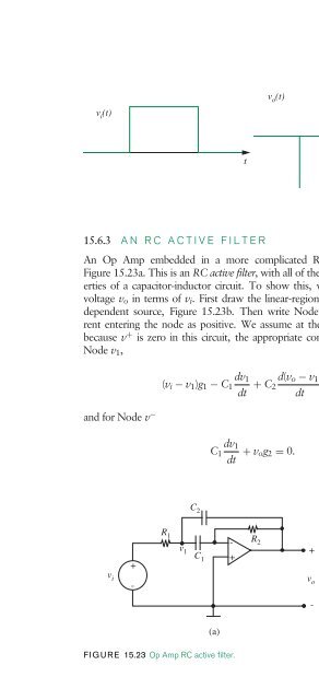
- Page 1770: into Equation 15.66, again noting v
- Page 1776: 864 CHAPTER FIFTEEN the operational
- Page 1780: 866 CHAPTER FIFTEEN the operational
- Page 1784: 868 CHAPTER FIFTEEN the operational
- Page 1788: 870 CHAPTER FIFTEEN the operational
- Page 1792: 872 CHAPTER FIFTEEN the operational
- Page 1796: 874 CHAPTER FIFTEEN the operational
- Page 1800: 876 CHAPTER FIFTEEN the operational
- Page 1804: 878 CHAPTER FIFTEEN the operational
- Page 1808: 880 CHAPTER FIFTEEN the operational
- Page 1812: 882 CHAPTER FIFTEEN the operational
- Page 1816: 884 CHAPTER FIFTEEN the operational
- Page 1820: 886 CHAPTER FIFTEEN the operational
- Page 1824:
888 CHAPTER FIFTEEN the operational
- Page 1828:
890 CHAPTER FIFTEEN the operational
- Page 1832:
892 CHAPTER FIFTEEN the operational
- Page 1836:
894 CHAPTER FIFTEEN the operational
- Page 1840:
896 CHAPTER FIFTEEN the operational
- Page 1844:
898 CHAPTER FIFTEEN the operational
- Page 1848:
900 CHAPTER FIFTEEN the operational
- Page 1852:
902 CHAPTER FIFTEEN the operational
- Page 1858:
diodes 16 16.1 INTRODUCTION The dio
- Page 1862:
10 pA i D v D 16.2 Semiconductor Di
- Page 1866:
where the diode current iD is zero
- Page 1870:
+ - (a) Circuit 0.6 V + - Rd R + v
- Page 1874:
16.4 Nonlinear Analysis with RL and
- Page 1878:
16.4 Nonlinear Analysis with RL and
- Page 1882:
+10 0 -10 v i (V) Hence the circuit
- Page 1886:
16.6 SUMMARY ◮ The following is a
- Page 1890:
problem 16.1 For the two circuits s
- Page 1894:
voltages 10 V 0 -10 V Diode ON Diod
- Page 1902:
appendix a maxwell’s equations an
- Page 1906:
The preceding equation says that in
- Page 1910:
x y S x S y Closed surface envelopi
- Page 1914:
the point-mass simplification, in w
- Page 1918:
d + V - + v 3 - a +v1- b c +v 4 - F
- Page 1922:
A.3 Deriving the Resistance of a Pi
- Page 1930:
appendix b trigonometric functions
- Page 1934:
B.4 PRODUCTS cos(θ1) cos(θ2) = 1
- Page 1938:
appendix c C.1 MAGNITUDE AND PHASE
- Page 1944:
948 APPENDIX C complex numbers C.2
- Page 1948:
950 APPENDIX C complex numbers For
- Page 1952:
952 APPENDIX C complex numbers Here
- Page 1958:
appendix d
- Page 1964:
958 APPENDIX D solving simultaneous
- Page 1968:
960 answers to selected problems Ex
- Page 1972:
962 answers to selected problems Pr
- Page 1976:
964 answers to selected problems ch
- Page 1980:
966 answers to selected problems Pr
- Page 1984:
968 answers to selected problems Ex
- Page 1990:
figure acknowledgements Figure 1.18
- Page 1996:
974 INDEX Cartesian-to-polar coordi
- Page 2000:
976 INDEX energy storage elements,
- Page 2004:
978 INDEX lightbulb circuit, 5 8 Li
- Page 2008:
980 INDEX OR function, 257, 261 OR
- Page 2012:
982 INDEX Siemens, 31, 48 signal cl
- Page 2016:
984 INDEX under-compensation, 753 7