instruction manual • gebruiksaanwijzing • intructions de montage ...
instruction manual • gebruiksaanwijzing • intructions de montage ...
instruction manual • gebruiksaanwijzing • intructions de montage ...

You also want an ePaper? Increase the reach of your titles
YUMPU automatically turns print PDFs into web optimized ePapers that Google loves.
T0356<br />
INSTRUCTION MANUAL <strong>•</strong> GEBRUIKSAANWIJZING <strong>•</strong> INTRUCTIONS DE MONTAGE <strong>•</strong> ANLEITUNG<br />
WARNING ! This R/C kit and the mo<strong>de</strong>l<br />
you will build is not a toy.<br />
LET OP ! Deze bouwdoos van een<br />
radiobestuurd vliegtuig is geen<br />
speelgoed.<br />
ATTENTION ! Ce kit d’avion R/C n’est<br />
pas un jouet.<br />
ACHTUNG ! Dieser Bausatz von<br />
ferngesteurte mo<strong>de</strong>l<br />
ist kein Spielzeug.<br />
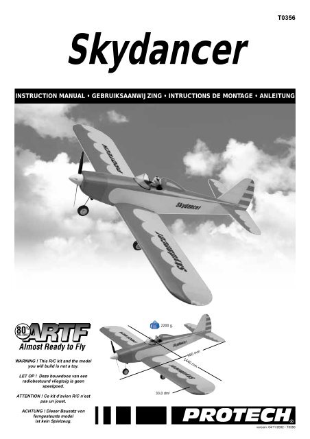
Skydancer<br />
2200 g.<br />
33,0 dm 2<br />
960 mm<br />
1440 mm<br />
version: 04/11/2002 <strong>•</strong> T0356
Specifications / Specificaties /<br />
Spécifications / Technische daten<br />
Wing span: 1440 mm<br />
Length: 960 mm<br />
Wing area: 33,0 dm 2<br />
Wing loading: 66,7 g/dm 2<br />
Flying weight: 2200 g<br />
Radio required: 4 ch radio with<br />
4 STD servos<br />
Enigine: 2C .40-.46 size<br />
4C .52 size<br />
I.C. Engine<br />
Kit content / Inhoud van <strong>de</strong> bouwdoos /<br />
Contenu <strong>de</strong> la boîte / Bausatzinhalt<br />
1. Wing parts<br />
2. Rud<strong>de</strong>r<br />
3. Elevator<br />
4. Fuselage<br />
5. Windscreen<br />
6. Cockpit fairing<br />
7. Wing joiner<br />
8. Servohol<strong>de</strong>r<br />
9. Motorcowling<br />
10. Spinner<br />
11. Nose steering<br />
12. Un<strong>de</strong>rcarriage<br />
13. Fueltank<br />
14. Enginemount<br />
2 - Skydancer<br />
10<br />
14<br />
9<br />
11<br />
Spanwijdte: 1440 mm<br />
Lengte: 960 mm<br />
Vleugelopp.: 33,0 dm 2<br />
Vleugelbel.: 66,7 g/dm 2<br />
Vlieg gewicht: 2200 g<br />
Radio besturing: 4 kanaals radio<br />
STD servo’s<br />
Motor: 2C .40-.46 size<br />
4C .52 size<br />
I.C. Engine<br />
13<br />
12<br />
5<br />
1. Vleugel<strong>de</strong>len<br />
2. Richtingsroer<br />
3. Hoogteroer<br />
4. Romp<br />
5. Venster<br />
6. Cockpit hoofdsteun<br />
7. Vleugelbevestiging<br />
8. Servohou<strong>de</strong>r<br />
9. Motorkap<br />
10. Spinner<br />
11. Neuswiel<br />
12. Landingsgestel<br />
13. Brandstoftank<br />
14. Motorsteun<br />
1<br />
8<br />
7<br />
Envergure: 1440 mm<br />
Longueur: 960 mm<br />
Surface alaire: 33,0 dm 2<br />
Charge alaire: 66,7 g/dm 2<br />
Poids en vol: 2200 g<br />
Radio requise: 4 voies avec<br />
4 servos STD<br />
Moteur: 2C .40-.46 size<br />
4C .52 size<br />
I.C. Engine<br />
6<br />
4<br />
1. Panneaux d’ailes<br />
2. Dérive<br />
3. Stabilisateur<br />
4. Fuselage<br />
5. Verrière <strong>de</strong> cabine<br />
6. Appuie-tête<br />
7. Clé d’aile<br />
8. Support servo<br />
9. Capot moteur<br />
10. Cône d’hélice<br />
11. Train avant<br />
12. Train principal<br />
13. Réservoir<br />
14. Bâti moteur<br />
Spannweite: 1440 mm<br />
Länge: 960 mm<br />
Tragflügelinhalt: 33,0 dm 2<br />
Gesamtflachenbelastung:<br />
66,7 g/dm 2<br />
Fluggewicht: 2200 g<br />
Funkfernsteuerung:4 Kanal<br />
Steuerung mit<br />
4 STD servo<br />
Motor: 2C .40-.46 size<br />
4C .52 size<br />
I.C. Engine<br />
2<br />
1. Flügelflächen<br />
2. Seitenleitwerk<br />
3. Höhenleitwerk<br />
4. Rumpf<br />
5. Kabinehaube<br />
6. Kunststoff Rumpfteil<br />
7. Flächenverbin<strong>de</strong>r<br />
8. Servohälter<br />
9. Motorhaube<br />
10. Spinner<br />
11. Lenkbares Bugfahrwerk<br />
12. Hauptfahrwerk<br />
13. Kraftstofftank<br />
14. Motorträger<br />
3
Important Safety Notes.<br />
Be sure to read right through the <strong>instruction</strong>s covering assembly and operation of your mo<strong>de</strong>l before you attempt to operate it for the first time. You alone are<br />
responsible for the safe operation of your radio-controlled mo<strong>de</strong>l. Young people should only be permitted to build and fly these mo<strong>de</strong>ls un<strong>de</strong>r the <strong>instruction</strong> and<br />
supervision of an adult who is aware of the hazards involved in this activity.<br />
Use only matching polarised connectors. All cables, connectors and the battery if home-assembled must be insulated to prevent short circuits. Never attempt to<br />
combine different types of plug and socket - e.g. tin-plated and gold-plated types - as such combinations are bound to be unreliable.<br />
NC batteries are capable of holding and releasing enormous amounts of energy, and as such represent a constant hazard of explosion and fire.<br />
We have no control over the way you build and operate your RC mo<strong>de</strong>l aircraft, and for this reason we are obliged to <strong>de</strong>ny all liability for acci<strong>de</strong>nts. All we can do is<br />
point out the hazards and make sure you are aware of them.<br />
If you need help, please enlist the aid of an experienced mo<strong>de</strong>ller, a mo<strong>de</strong>l club or enrol at a mo<strong>de</strong>l flying training school, Mo<strong>de</strong>l shops and the specialist mo<strong>de</strong>l<br />
press are also good sources of information. The best course is always to join a club and fly at the approved mo<strong>de</strong>l flying site.<br />
Rubber bands <strong>de</strong>teriorate with age and become brittle. Replace them from time to time to maintain the safety and reliability of your mo<strong>de</strong>l. Stretch all rubber bands<br />
before use to check that they are still strong enough for their purpose.<br />
Motors should only be run in the open air! The powerful suction of the propeller and the volume of air which it accelerates can easily lead to acci<strong>de</strong>nts in enclosed<br />
spaces (e.g. pictures falling down, curtains sucked into the propeller). The mo<strong>de</strong>l must be held securely by an assistant at all times.<br />
Keep well clear of the rotational plane of propellers - don't stand in line with it or in front of it. You never know when some part may come loose and fly off at high<br />
speed, hitting you or anybody else in the vicinity. Never touch the revolving propeller with any object.<br />
There must be no chance of any object getting in the way of the propeller and preventing it rotating.<br />
Take care with loose clothing such as scarves, loose shirts etc. Flapping cloth can easily be sucked into the area of the propeller and then get tangled in it.<br />
If you start your motor when the mo<strong>de</strong>l is standing on loose or sandy ground, the propeller will suck up sand and dust and hurl it around. and it could easily get in<br />
your eyes. Wear protective goggles at such times.<br />
Every time you intend to operate your mo<strong>de</strong>l check carefully that it and everything attached to it (e.g. propeller, gearbox,RC components etc.) are in good condition<br />
and undamaged. If you find a fault do not fly the mo<strong>de</strong>l until you have corrected it.<br />
Satisfy yourself that your frequency is vacant before you switch on. Radio interference caused by unknown sources can occur at any time without warning. If this<br />
should happen, your mo<strong>de</strong>l will be uncontrollable and completely unpredictable. Never leave your radio control system unguar<strong>de</strong>d, as other people might pick it up<br />
and try to use it.<br />
Check that nothing is in the way of the propeller before you switch on the electric motor. Never attempt to stop the spinning propeller.Electric motors with a propeller<br />
attached should only be run when installed securely.<br />
lf you are to fly your mo<strong>de</strong>l safely and avoid problems it is essential that you are aware of its position and attitu<strong>de</strong> throughout each flight - so don't let it fly too far<br />
away! lf you <strong>de</strong>tect a control problem or interference during a flight,immediately land the mo<strong>de</strong>l to prevent a potential acci<strong>de</strong>nt Note that the transmitter throttle stick<br />
must be set to the OFF (motor stopped) position before you switch on the power system. To avoid the electric motor starting unexpectedly, switch on the transmitter<br />
first. then the receiving system. Use the reverse sequence when switching off: receiver first, then the transmitter. Check that the control surfaces move in the correct<br />
"sense" when you operate the sticks.<br />
Please don't misun<strong>de</strong>rstand the purpose of these notes. We only want to make you aware of the many dangers and hazards which can arise if you lack knowledge<br />
and experience, or work carelessly or irresponsibly. If you take reasonable care mo<strong>de</strong>l flying is a highly creative, instructive, enjoyable and relaxing pastime.<br />
Belangrijke Veiligheidsinstructies<br />
Lees <strong>de</strong> instructies betreffen<strong>de</strong> <strong>montage</strong> en werking van je mo<strong>de</strong>l vooraleer u het <strong>de</strong> eerste maal in gebruik neemt. U alleen bent verantwoor<strong>de</strong>lijk voor <strong>de</strong> veilige<br />
werking van uw radiobestuurd mo<strong>de</strong>l. Kin<strong>de</strong>ren zijn enkel toegestaan om <strong>de</strong>ze mo<strong>de</strong>llen te bouwen en te vliegen on<strong>de</strong>r het toeziend oog van een volwassene, die<br />
zich bewust is van <strong>de</strong> gevaren die dit met zich meebrengt.<br />
Gebruik enkel passen<strong>de</strong> gepolariseer<strong>de</strong> verbindingsstukken. Alle kabels, verbindingsstukken en <strong>de</strong> batterij, indien <strong>de</strong>ze zelf samengesteld is, moeten geïsoleerd<br />
wor<strong>de</strong>n om kortsluiting te voorkomen. Poog nooit verschillen<strong>de</strong> types van pluggen en contacten te kombineren (vb.tin-en goudcontacten), daar zulke combinaties<br />
onbetrouwbaar zijn.<br />
NC-batterijen zijn geschikt om enorme hoeveelhe<strong>de</strong>n energie vast te hou<strong>de</strong>n en vrij te geven. Zodoen<strong>de</strong> vertegenwoordigt een batterij een constant risico op<br />
explosie en brandgevaar.<br />
Wij hebben geen controle over <strong>de</strong> manier waarop u het RC-vliegtuig bouwt en gebruikt. Daarom zijn wij verplicht om alle aansprakelijkheid voor ongevallen van <strong>de</strong><br />
hand te wijzen. Het enige dat in onze mogelijkhe<strong>de</strong>n ligt is u te waarschuwen voor <strong>de</strong> risico’s.<br />
Als u hulp nodig heeft, roep dan <strong>de</strong> bijstand van een ervaren mo<strong>de</strong>lbouwer of een mo<strong>de</strong>lbouwclub in, of schrijf u in bij een mo<strong>de</strong>lvliegclub. Mo<strong>de</strong>lshops en <strong>de</strong><br />
gespecialiseer<strong>de</strong> pers zijn eveneens een geschikte bron van informatie. De beste les is echter zich aan te sluiten bij een club en te vliegen op <strong>de</strong> goedgekeur<strong>de</strong><br />
vliegplaatsen.<br />
Rubber elastieken verslijten met het gebruiken en wor<strong>de</strong>n broos. Vervang ze tijdig, zodoen<strong>de</strong> stelt u <strong>de</strong> veiligheid en <strong>de</strong> betrouwbaarheid van uw mo<strong>de</strong>l veilig. Span<br />
alle rubber elastieken op vooraleer u ze gebruikt om te controleren of ze nog sterk genoeg zijn.<br />
Motoren mogen enkel buiten in openlucht lopen! De sterke zuigkracht van <strong>de</strong> propeller en <strong>de</strong> luchtverplaatsing die <strong>de</strong>ze veroorzaakt, kan in kleine ruimten makkelijk<br />
een ongeval tot gevolg hebben (vb. schil<strong>de</strong>rijen die naar bene<strong>de</strong>n vallen, een gordijn dat in <strong>de</strong> propeller gezogen wordt). Het mo<strong>de</strong>l moet steeds stevig wor<strong>de</strong>n<br />
vastgehou<strong>de</strong>n door een helper.<br />
Houdt <strong>de</strong> rotatiebaan van een propeller vrij, sta er nooit voor of in <strong>de</strong> lijn van <strong>de</strong> propeller. Er kan steeds een <strong>de</strong>el loskomen en met hoge snelheid wegvliegen, zodat<br />
het uzelf of iemand an<strong>de</strong>rs in <strong>de</strong> omgeving kan verwon<strong>de</strong>n. Raak <strong>de</strong> ronddraaien<strong>de</strong> propeller nooit met enig voorwerp aan. Vermijdt steeds dat welk voorwerp ook<br />
het draaien van <strong>de</strong> propeller verhin<strong>de</strong>rt.<br />
Pas op met losse kleding zoals sjaals, losse shirts, … Losse kleding kan makkelijk in <strong>de</strong> propeller gezogen wor<strong>de</strong>n.<br />
Als u <strong>de</strong> motor start terwijl <strong>de</strong>ze op losse of zan<strong>de</strong>rige grond staat, zal <strong>de</strong> propeller het zand opzuigen en rondslingeren zodat het in je ogen kan komen. Draag dus<br />
steeds een veiligheidsbril op zo’n momenten.<br />
Controleer, elke keer als u een mo<strong>de</strong>l wil gebruiken, zorgvuldig of het mo<strong>de</strong>l en alles wat erbij hoort (vb. propeller, aandrijving, RC-on<strong>de</strong>r<strong>de</strong>len, …) in goe<strong>de</strong> staat en<br />
onbeschadigd is. Als u een fout bemerkt, vlieg dan niet met het mo<strong>de</strong>l tot u <strong>de</strong> fout hebt opgelost.<br />
Verzeker uzelf ervan dat <strong>de</strong> frequentie vrij is vooraleer u <strong>de</strong> zen<strong>de</strong>r aanzet. Radiostoringen veroorzaakt door vreem<strong>de</strong> bronnen kunnen op elk moment en zon<strong>de</strong>r<br />
waarschuwing voorkomen. Als dit gebeurt is je mo<strong>de</strong>l oncontroleerbaar en volledig onvoorspelbaar. Laat uw radiobesturing nooit onbewaakt achter, an<strong>de</strong>re mensen<br />
zou<strong>de</strong>n kunnen proberen het te gebruiken.<br />
Controleer of er niets in <strong>de</strong> baan van <strong>de</strong> propeller is vooraleer u <strong>de</strong> electromotor aanzet. Probeer nooit <strong>de</strong> draaien<strong>de</strong> propeller te stoppen. Electromotoren verbon<strong>de</strong>n<br />
met een propeller mogen enkel lopen als <strong>de</strong>ze veilig geïnstalleerd is.<br />
Als u uw mo<strong>de</strong>l veilig wil vliegen en u wil problemen vermij<strong>de</strong>n, dan is het essentieel dat u zich bewust bent van zijn positite en hoogte tij<strong>de</strong>ns ie<strong>de</strong>re vlucht. Laat het<br />
dus niet te ver weg vliegen ! Als u een controleprobleem of storingen ont<strong>de</strong>kt geduren<strong>de</strong> een vlucht, landt dan onmid<strong>de</strong>llijk om een mogelijk ongeval te voorkomen.<br />
Bemerk dat <strong>de</strong> zen<strong>de</strong>rstick voor <strong>de</strong> motorfunctie in <strong>de</strong> off-stand moet staan vooraleer u het systeem aanzet. Om te voorkomen dat <strong>de</strong> electromotor onverwacht start,<br />
zet eerst <strong>de</strong> zen<strong>de</strong>r aan, later pas <strong>de</strong> ontvanger. Gebruik <strong>de</strong> omgekeer<strong>de</strong> volgor<strong>de</strong> bij het afzetten : eerst <strong>de</strong> ontvanger, dan <strong>de</strong> zen<strong>de</strong>r. Controleer of <strong>de</strong> roeren in <strong>de</strong><br />
juiste richting bewegen als u <strong>de</strong> sticks gebruikt.<br />
Heb begrip voor het doel van <strong>de</strong>ze opmerkingen. Wij willen u enkel opmerkzaam maken voor <strong>de</strong> vele gevaren en risico’s die zich kunnen voordoen als u kennis en<br />
ervaring mist, nonchalant of onverantwoor<strong>de</strong>lijk te werk gaat.<br />
Als u re<strong>de</strong>lijk zorg draagt, is mo<strong>de</strong>lvliegen een zeer creatieve, leerrijke, plezierige en ontspannen<strong>de</strong> vrijetijdsbesteding.<br />
Skydancer - 3
4 - Skydancer<br />
Conseils <strong>de</strong> sécurité importants<br />
Avant <strong>de</strong> tenter la première mise en service, la totalité <strong>de</strong>s <strong>instruction</strong>s <strong>de</strong> <strong>montage</strong> et d’utilisation <strong>de</strong>vront être attentivement lues. Vous êtes seul responsable <strong>de</strong> la<br />
sécurité d’utilisation <strong>de</strong> votre modèle volant R/C. Il est conseillé aux adolescents <strong>de</strong> se faire assister pour la construction et pour les premiers vols par un adulte déjà<br />
familiarisé au danger que peut représenter un modéle radiocommandé.<br />
Utilisez toujours <strong>de</strong>s connecteurs adaptés, avec sécurité contre les inversions <strong>de</strong> polarité. Tous les conducteurs <strong>de</strong> courant, les connecteurs ainsi que les batteries<br />
<strong>de</strong> propulsion <strong>de</strong> confection personnelle <strong>de</strong>vront être parfaitement isolés contre les courts-circuits. N’utilisez jamais <strong>de</strong>s combinaisons <strong>de</strong> connecteurs, par ex. <strong>de</strong>s<br />
contacts en métal ordinaire avec <strong>de</strong>s contacts dorés, car dans ce cas aucune sécurité <strong>de</strong> fonctionnement ne peut être garantie. Evitez les court-circuits et les<br />
inversions <strong>de</strong> polarité car la forte énergie contenue dans les batteries NC pourrait entraîner un danger d’explosion et d’incendie.<br />
Un modèle volant R/C ne peut évoluer correctement que s’il a été construit et réglé conformément aux <strong>instruction</strong>s <strong>de</strong> <strong>montage</strong> et seule une utilisation pru<strong>de</strong>nte et<br />
responsable évitera <strong>de</strong> provoquer <strong>de</strong>s dommages corporels ou matériels.<br />
Le fabricant n’a cependant aucune possibilité d’influencer la construction et l’utilisation d’un modèle <strong>de</strong> sa production. C’est pourquoi nous attirons l’attention sur<br />
les dangers représentés en dégageant toute responsabilité.<br />
Faites-vous assister par un modéliste expérimenté, ou inscrivez - vous dans une association ou une école <strong>de</strong> pilotage. Vous pourrez en outre consulter votre<br />
reven<strong>de</strong>ur et la presse spécialisée sur le sujet. Le mieux est <strong>de</strong> faire partie d’un club d’aéromodélisme pour pouvoir voler sur un terrain autorisé.<br />
Les ban<strong>de</strong>s élastiques vieillissent, elles <strong>de</strong>viennent cassantes et inutilisables dans le temps. C’est la raison pour laquelle il conviendra <strong>de</strong> les remplacer régulièrement<br />
par <strong>de</strong>s neuves. Avant chaque utilisation, vérifier la solidité du caoutchouc par <strong>de</strong>s essais <strong>de</strong> tension.<br />
Effectuez les essais <strong>de</strong> fonctionnement uniquement à l’extérieur. La forte aspiration <strong>de</strong> l’hélice et la masse d’air rapi<strong>de</strong>ment accélérée <strong>de</strong>rrière son champ <strong>de</strong> rotation<br />
peuvent provoquer un acci<strong>de</strong>nt dans une pièce fermée (la chute d’un tableau, l’aspiration <strong>de</strong>s ri<strong>de</strong>aux, etc.). Le modèle <strong>de</strong>vra être fermement tenu par un ai<strong>de</strong>.<br />
Ne vous tenez jamais dans le champ <strong>de</strong> rotation <strong>de</strong> l’hélice! Une partie peut se détacher et être éjectée à très haute vitesse avec une forte inertie et vous toucher, ou<br />
une tierce personne. Veillez également à ce qu’aucun objet quelconque ne vienne en contact avec l’hélice en rotation! Le blocage <strong>de</strong> l’hélice par un objet quelconque<br />
doit être absolument exclu.<br />
Veillez également aux vêtements flottants, tels qu’écharpe ou cravate qui peuvent être aspirés et s’enrouler sur l’hélice.Lorsqu’un modèle se trouve sur un sol<br />
sablonneux avec l’hélice en rotation, celle-ci peut aspirer du sable ou <strong>de</strong>s gravillons et vous les projeter dans les yeux. Portez <strong>de</strong>s lunettes <strong>de</strong> protection si<br />
nécessaire.<br />
Avant chaque utilisation, contrôlez le modèle et toutes les pièces qui y sont rattachées (par ex. hélice, réducteur, élément R/C etc..) afin <strong>de</strong> vérifier leur fixation ou<br />
détecter une possible détérioration. Ce n’est qu’après avoir remédié à tous les défauts éventuels que le modèle sera en ordre <strong>de</strong> vol. Assurez-vous que la fréquence<br />
que vous utilisez est libre avant <strong>de</strong> mettre votre émetteur en contact! Une perturbation peut toujours se produire pour une cause inconnue, sans prévenir! Le modèle<br />
<strong>de</strong>vient alors incontrôlable et livré à lui-même! Ne laissez pas votre émetteur sans surveillance pour éviter une manipulation par un tiers.<br />
Ne mettez le moteur électrique en contact que si aucun objet ou autre ne se trouve dans le champ <strong>de</strong> rotation <strong>de</strong> l’hélice. Ne tentez pas d’arrêter l’hélice à la main.<br />
Ne faites tourner le moteur avec l’hélice que lorsqu’il est monté dans le modèle.<br />
La position du modèle doit toujours être nettement i<strong>de</strong>ntifiable durant tout le vol pour garantir un pilotage sûr. Si l’on remarque l’influence d’une perturbation durant<br />
le vol, se préparer immédiatement à atterrir par mesure <strong>de</strong> sécurité.<br />
Faites une vérification complète <strong>de</strong> l’installation R/C et <strong>de</strong> la portée <strong>de</strong> votre radiocomman<strong>de</strong> ainsi que du modèle pour vous assurer du bon fonctionnement avant<br />
chaque vol.<br />
Assurez-vous que la comman<strong>de</strong> du moteur soit sur la position ‘gaz coupé’ sur l’émetteur. Mettez d’abord l’émetteur en contact , ensuite la réception pour éviter un<br />
démarrage incontrôlé du moteur électrique. Procé<strong>de</strong>z inversement pour couper le contact : d’abord la réception, ensuite l’émetteur.<br />
Vérifiez si les gouvernes bougent dans le sens correspondant au manche <strong>de</strong> comman<strong>de</strong>.<br />
Ces conseils mettent en évi<strong>de</strong>nce la diversité <strong>de</strong>s dangers pouvant résulter d’une manipulation incorrecte et irresponsable. Ces observations vous permettront <strong>de</strong><br />
pratiquer en toute sécurité ce loisir créatif et éducatif que représente l’aéromodélisme. Bon vol.<br />
Wichtige Sicherheitshinweise<br />
Vor <strong>de</strong>m Versuch <strong>de</strong>r ersten Inbetriebnahme muß die gesamte Betriebs- und Montageanleitung sorgfältig gelesen wer<strong>de</strong>n. Sie alleine sind verantwortlich für <strong>de</strong>n<br />
sicheren Betrieb Ihres RC-Flugmo<strong>de</strong>lls. Bei Jugendlichen muß <strong>de</strong>r Bau und Betrieb von einem Erwachsenen, <strong>de</strong>r mit <strong>de</strong>n Gegebenheiten und möglichen Gefahren<br />
eines RC-Flugmo<strong>de</strong>lls vertraut ist, verantwortlich überwacht wer<strong>de</strong>n.<br />
Verwen<strong>de</strong>n Sie immer nur passen<strong>de</strong>, verpolungssichere Steckverbindungen. Alle stromführen<strong>de</strong>n Leitungen, Steckverbindungen, sowie die Antriebsbatterie, bei<br />
Selbstkonfektionierung, kurzschlußsicher isolieren. Kombinieren Sie niemals unterschiedliche, z. B. Blech- und Goldkontakte, da hier keine sichere Funktion<br />
gewährleistet ist.<br />
Kurzschlüsse und Falschpolungen vermei<strong>de</strong>n.<br />
Durch die hohe Energie <strong>de</strong>r NC-Batterien besteht Explosions- und Brandgefahr.<br />
Ein RC-Flugmo<strong>de</strong>ll kann nur funktionsfähig sein und <strong>de</strong>n Erwartungen entsprechen, wenn es im Sinne <strong>de</strong>r Bauanleitung sorgfältigst gebaut wur<strong>de</strong>. Nur ein<br />
vorsichtiger und überlegter Umgang beim Betrieb schützt vor Personen- und Sachschä<strong>de</strong>n. Mo<strong>de</strong>lfliegen will gelernt sein.<br />
Bitte, wen<strong>de</strong>n Sie sich dazu an erfahrene Mo<strong>de</strong>llflieger, an Vereine o<strong>de</strong>r Mo<strong>de</strong>llflugschulen. Ferner sei auf <strong>de</strong>n Fachhan<strong>de</strong>l und die einschlägige Fachpresse<br />
verwiesen. Am besten als Club-Mitglied auf zugelassenem Mo<strong>de</strong>llflugplatz fliegen.<br />
Gummiringe altern und wer<strong>de</strong>n mit <strong>de</strong>r Zeit sprö<strong>de</strong> und unbrauchbar. Sie müssen <strong>de</strong>shalb von Zeit zu Zeit gegen neue ausgetauscht wer<strong>de</strong>n. Überprüfen Sie vor<br />
je<strong>de</strong>r Anwendung <strong>de</strong>n verwen<strong>de</strong>ten Gummi, durch Dehnversuche, auf seine Festigkeit.<br />
Testläufe nur im Freien durchführen. Die starke Sogwirkung <strong>de</strong>r Luftschraube und die schnell beschleunigte Lutftmenge kann in einem geschlossenen Raum zu<br />
Unfällen (z.B durch herabfallen<strong>de</strong> Bil<strong>de</strong>r, Ansaugen von Vorhängen) führen. Das Mo<strong>de</strong>ll muß von einem Helfer festgehalten wer<strong>de</strong>n.<br />
Sich niemals in o<strong>de</strong>r vor <strong>de</strong>r Drehebene von Luftschrauben aufhalten! Es könnte sich doch einmal ein Teil davon lösen und mit hoher Geschwindigkeit und viel<br />
Energie wegfliegen und Sie o<strong>de</strong>r Dritte treffen. Darauf achten daß kein sonstiger Gegenstand mit einer Luftschraube in Berührung kommt !<br />
Die Blockierung <strong>de</strong>r Luftschraube durch irgendwelche Teile, muß ausgeschlossen sein.<br />
Vorsicht bei losen Kleidungsstücken wie Schals, weiten Hem<strong>de</strong>n usw : sie wer<strong>de</strong>n vom Propellerstrahl angesaugt und können in <strong>de</strong>n Luftschraubenkreis gelangen.<br />
Steht ein Mo<strong>de</strong>ll mit drehen<strong>de</strong>r Luftschraub z.B. auf sandigem Grund, so wer<strong>de</strong>n Sand o<strong>de</strong>r Schmutzpartikel angesaugt und herumgewirbelt, die u.ä. Augenschä<strong>de</strong>n<br />
hervorrugen können. Nötigenfalls Schutzbrille tragen.<br />
Überprüfen Sie vor je<strong>de</strong>r Inbetriebnahme das Mo<strong>de</strong>ll und alle an ihm gekoppelten Teile (z.B. Luftschrauben, Getriebe, RC-Teile usw) auf festen Sitz und mögliche<br />
Beschädigungen. Das Mo<strong>de</strong>ll darf erst nach Beseitigung aller Mängel in Betrieb genommen wer<strong>de</strong>n.<br />
Vergewissern Sie sich, daß die verwen<strong>de</strong>te Frequenz frei ist. Erst dann einschalten ! Funkstörungen, verursacht durch Unbekannte können stets ohne Vorwarnung<br />
auftreten ! Das Mo<strong>de</strong>ll ist dann steuerlos und unberechenbar ! Fernlenkanlage nicht unbeaufsichtigt lassen, um ein Betätigen durch Dritte zu verhin<strong>de</strong>rn.<br />
Elektromotor nur einschalten, wenn nichts im Drehbereich <strong>de</strong>r Luftschraube ist. Nicht versuchen die laufen<strong>de</strong> Luftschraube anzuschalten. Elektromotor mit<br />
Luftschraube nur im fest eingebauten Zustand laufen lassen.<br />
Die Fluglage <strong>de</strong>s Mo<strong>de</strong>lls muß während <strong>de</strong>s gesamten Fluges immer ein<strong>de</strong>utig erkennbar sein, um immer ein sicheres Steuern und Ausweichen zu gewährleisten.<br />
Machen sich während <strong>de</strong>s Fluges Funktionsbeeinträchtigungen/Störungen bemerkbar, muß aus Sicherheitsgrün<strong>de</strong>n sofort die Landung eingeleitet wer<strong>de</strong>n. Sie<br />
haben an<strong>de</strong>ren Luftfahrzeugen stets auszuweichen. Start- und Lan<strong>de</strong>flächen müssen frei von Personen und sonstigen Hin<strong>de</strong>rnissen sein.<br />
Dabei ist zu beachten, daß bei <strong>de</strong>r Inbetriebnahme die Motorsteuerfunktion am Sen<strong>de</strong>r immer zuerst in AUS-Stellung gebracht wird. Danach Sen<strong>de</strong>r und dann erst<br />
Empfangsanlage einschalten, um ein unkontrolliertes Anlaufen <strong>de</strong>s Elektromotors zu vermei<strong>de</strong>n. Geleichfalls gilt immer zuerst Empfangsanlage ausschalten, danach<br />
erst <strong>de</strong>n Sen<strong>de</strong>r. Überprüfen ie, daß die Ru<strong>de</strong>r sich entsprechend <strong>de</strong>r Steuerknüppelbetätigung bewegen.<br />
Mit diesen Hinweisen soll auf die vielfältigen Gefahren hingewiesen wer<strong>de</strong>n, die durch unsachgemäße und verantwortungslose Handhabung entstehen können.<br />
Richtig und gewissenhaft betrieben ist Mo<strong>de</strong>llflug eine kreative, lehrreiche und erholsame Fernzeitgestaltung.
Tools & items / Gereedschap & benodigdhe<strong>de</strong>n /<br />
Outils et équipements / Werkzeuge und erfor<strong>de</strong>rliches<br />
To assamble this airplane some tools are nee<strong>de</strong>d.<br />
Voor het samenstellen van het vliegtuig zijn er enkele gereedschappen nodig.<br />
Zum bauen dieses Flugzeug wer<strong>de</strong>n einige Werkzeuge gebraucht .<br />
Certains outils sont requis pour assembler cet avion.<br />
Sharp hobby knife / Scherp hobby mes /<br />
Couteau <strong>de</strong> mo<strong>de</strong>liste / Hobby messer<br />
Triangle / Driehoeks meetlat /<br />
Equerre / Winkel<br />
Drill / Boor / Perceuse à main / Handbohrer<br />
Needle nose pliers / Bek tang /<br />
Pince à becs / Beisszange<br />
Philips screw driver / Philips schroevendraaier /<br />
Tournevis Philips / Schraubendreher<br />
Scissors / Schaar / Ciseaux / Schere Wire cutter / Draad stripper /<br />
Pince coupante / Kneifzange<br />
Slow instant glue / secon<strong>de</strong>nlijm /<br />
Colle cyanoacrylate lente / Sekun<strong>de</strong>nkleber<br />
Epoxy glue / Epoxy lijm /<br />
Colle époxy / Epoxyd-Kleber<br />
Skydancer - 5
Assembling the ailerons / Monteren van <strong>de</strong> rolroeren /<br />
Assemblage <strong>de</strong>s ailerons / Montieren von die Querru<strong>de</strong>rn<br />
Glue the steering rod of the aileron<br />
with epoxy, and at the same<br />
moment, glue the hinges of the<br />
ailerons on both si<strong>de</strong>s with slow<br />
instant glue. Fix the parts during<br />
the drying proces.<br />
(Fig. 1-2-3-4-5)<br />
6 - Skydancer<br />
Fig. 1 Fig. 2<br />
Fig. 4 Fig. 5<br />
Verlijm <strong>de</strong> scharnieren van <strong>de</strong><br />
rolroeren met langzame<br />
secon<strong>de</strong>nlijm aan bei<strong>de</strong> kanten.<br />
Verlijm op het zelf<strong>de</strong> moment <strong>de</strong><br />
stuurstang voor het rolroer met<br />
epoxy. Goed vastzetten tij<strong>de</strong>ns het<br />
uithar<strong>de</strong>n.<br />
(Fig. 1-2-3-4-5)<br />
Collez la comman<strong>de</strong> <strong>de</strong> l’aileron<br />
avec <strong>de</strong> la colle époxy et en<br />
même temps collez à la colle<br />
cyanoacrylate lente les charnières<br />
<strong>de</strong>s ailerons. Maintenir durant<br />
le sèchage.<br />
(Fig. 1-2-3-4-5)<br />
Joining the wing halves / Monteren van <strong>de</strong> 2 vleugel<strong>de</strong>len /<br />
Assemblage <strong>de</strong>s panneaux d’ailes / Montierung von die Flügelflächen<br />
Fig. 6 Fig. 7 Fig. 8<br />
Drw 1<br />
Glue<br />
W42<br />
Glue the wingjoiner in 1 wing<br />
part with epoxy and let the glue<br />
dry (Fig. 6-7).<br />
Check the aligment (Drw1).<br />
Glue the wing parts straight<br />
together with epoxy (Fig. 8-9).<br />
Fix the parts together during the<br />
drying proces (Fig. 9).<br />
Verlijm het verbindingsstuk aan<br />
1 zij<strong>de</strong> in het vleugel<strong>de</strong>el met<br />
epoxy (Fig. 6-7). Laat <strong>de</strong> lijm<br />
goed uithar<strong>de</strong>n.<br />
Controleer <strong>de</strong> uitlijning (Drw 1).<br />
Verlijm <strong>de</strong> twee vleugel<strong>de</strong>len<br />
met epoxy recht tegen elkaar<br />
(Fig. 8-9). Klem <strong>de</strong> stukken goed<br />
tegen elkaar tij<strong>de</strong>ns het<br />
uithar<strong>de</strong>n (Fig. 9).<br />
Fig. 3<br />
Fig. 9<br />
Collez à l’époxy la clé d’aile<br />
dans un panneau d’aile, laissez<br />
sécher (Fig. 6-7).<br />
Collez à l’époxy les 2 panneaux<br />
ensemble (Fig. 8).<br />
Vérifier l’alignement (Drw1).<br />
Maintenez les pièces durant le<br />
séchage (Fig. 9).<br />
Glue
Installing the ailerons servos / Monteren van <strong>de</strong> rolroerservo /<br />
Installation du servo d’ailerons / Montierung von Querru<strong>de</strong>rservo<br />
Fig. 10 Fig. 11<br />
Fig. 13<br />
Fig. 16<br />
Draw the contourline from the<br />
servo-hol<strong>de</strong>r on the wing. Cut out<br />
the covering and glue the support<br />
with epoxy (Fig. 10-11-12).<br />
Drill the holes and screw the servo<br />
in place. Don’t forget to install the<br />
fittings of the servo (Fig. 13-14).<br />
Mount the controlhorn on the aileron.<br />
Attach the quicklink to the<br />
control rod and connect it to the<br />
servo-arm. Connect the Z-bend<br />
on the control horn of the aileron<br />
(Fig. 15-16).<br />
Markeer <strong>de</strong> contouren van <strong>de</strong><br />
servohou<strong>de</strong>r op <strong>de</strong> vleugel. Snij<br />
<strong>de</strong> folie weg en verlijm <strong>de</strong> hou<strong>de</strong>r<br />
met epoxy (Fig. 10-11-12).<br />
Boor <strong>de</strong> gaatjes en vijs <strong>de</strong> servo<br />
in positie. Let op monteer<br />
rubberen stootblokjes en bussen<br />
op <strong>de</strong> servo (Fig. 13-14).<br />
Monteer <strong>de</strong> controlhorn op het<br />
rolroer. Bevestig <strong>de</strong> kwiklink op <strong>de</strong><br />
stuurstang en bevestig <strong>de</strong>ze op <strong>de</strong><br />
servoarm. Bevestig <strong>de</strong> Z-hoek op<br />
<strong>de</strong> controlhorn van het rolroer<br />
(Fig. 15-16).<br />
Fig. 12<br />
Fig. 14 Fig. 15<br />
Tracez le contour du support<br />
servo sur l’aile. Découpez<br />
l’entoilage et collez le support<br />
avec <strong>de</strong> la colle epoxy (Fig. 10-<br />
11-12).<br />
Percez et vissez le servo en position.<br />
Attention il est impératif<br />
d’installer les blocs en<br />
caoutchouc et les entretoises sur<br />
le servo (Fig. 13-14).<br />
Fixez les chapes sur les tiges<br />
filetées et raccor<strong>de</strong>z-les aux<br />
guignols. Raccor<strong>de</strong>z les<br />
extrémités en Z au palonnier <strong>de</strong><br />
servo (Fig. 15-16).<br />
Skydancer - 7
Installing the landing gear / Monteren van het landingsgestel /<br />
Installation du train d’attérissage / Montierung von Hauptfahrwerk<br />
Cut out the covering of the slots<br />
of the un<strong>de</strong>rcarriage on the wing<br />
(Fig. 18).<br />
Insert the un<strong>de</strong>rcarriage (Fig. 19-<br />
20).<br />
Fix the plastic retainers with<br />
screws (Fig. 21-22-23).<br />
Place the plastic collar on the<br />
un<strong>de</strong>rcarriage, place the wheel<br />
and fix it with a wheelstopper<br />
(Fig. 24-25-26).<br />
8 - Skydancer<br />
Fig. 17 Fig. 18 Fig. 19<br />
Fig. 20 Fig. 21 Fig. 22<br />
Fig. 23 Fig. 24 Fig. 25<br />
Fig. 26<br />
Snij <strong>de</strong> bespanning weg op <strong>de</strong><br />
steunbalkjes van <strong>de</strong> vleugel ter<br />
hoogte van <strong>de</strong> landingsgestelslots<br />
(Fig. 18).<br />
Monteer <strong>de</strong> steunen van het<br />
landingsgestel (Fig. 19-20).<br />
Monteer <strong>de</strong> plastieke bevestigingsplaatjes<br />
met vijzen (Fig. 21-<br />
22-23).<br />
Schuif <strong>de</strong> plastieke ron<strong>de</strong>l en<br />
daarna het wiel op <strong>de</strong> steun en<br />
bevestig <strong>de</strong>ze met een wielstop<br />
(Fig. 24-25-26).<br />
Découpez l’entoilage sur l’aile au<br />
niveau <strong>de</strong> l’emplacement <strong>de</strong>s<br />
jambes <strong>de</strong> train (Fig. 18).<br />
Insérez les jambes (Fig. 19-20).<br />
Fixez à l’ai<strong>de</strong> <strong>de</strong>s vis les fixations<br />
plastiques du train d’attérissage<br />
(Fig. 21-22-23).<br />
Sur chaque axe <strong>de</strong> roue, installez<br />
l’entretoise plastique, installez la<br />
roue et bloquez-la avec l’arrêt<br />
(Fig. 24-25-26).
Fixing the wing / Bevestigen van <strong>de</strong> vleugel /<br />
Fixation <strong>de</strong> l’aile / Befestigung von Flügel<br />
Fig. 27 Fig. 28 Fig. 29<br />
Fig. 30 Fig. 31<br />
Fig. 35<br />
Mark the center of the two fixation<br />
holes on the fixation part<br />
(W43) as shown (Fig. 27-28-29).<br />
Drill the holes in the fixation part<br />
(Fig. 30). Make sure the holes perfectly<br />
aligned with the holes in the<br />
fuselage.<br />
Place the wing in position and<br />
align with the fuselage (Drw 2).<br />
Mark the holes of the fixation part<br />
on the wing (Drw. 2). Drill the two<br />
holes through the wing.<br />
Screw the wing, with the 2 <strong>de</strong>livered<br />
screws, to the fuselage<br />
(Fig. 31-32-33-34-35).<br />
Plaats en markeer <strong>de</strong> gaatjes op<br />
<strong>de</strong> versteviger (W43) (Fig. 27-28-<br />
29).<br />
Boor <strong>de</strong> gaatjes in <strong>de</strong> versteviger<br />
(Fig. 30), let op dat <strong>de</strong> gaten perfect<br />
overeenkomen met <strong>de</strong>ze in<br />
<strong>de</strong> romp.<br />
Plaats <strong>de</strong> vleugel op <strong>de</strong> romp,<br />
plaats <strong>de</strong> versteviger op <strong>de</strong><br />
vleugel en markeer <strong>de</strong> gaten (Drw.<br />
2). Boor <strong>de</strong> gaten door <strong>de</strong> vleugel.<br />
Bevestig <strong>de</strong> vleugel met <strong>de</strong> twee<br />
meegelever<strong>de</strong> vijzen (Fig. 30-31-<br />
32-33-34-35).<br />
A=A<br />
B=B<br />
Fig. 32 Fig. 33 Fig. 34<br />
Drw 2<br />
Placez et marquez les trous <strong>de</strong><br />
passage <strong>de</strong>s vis sur le renfort<br />
(W43) (Fig. 27-28-29).<br />
Percez le renfort (Fig. 30).<br />
Placez l’aile sur le fuselage,<br />
alignez-la avec le fuselage (Drw<br />
2).<br />
Placez le renfort sur l’aile,<br />
marquez les trous et percez l’aile.<br />
Fixez l’aile sur le fuselage à l’ai<strong>de</strong><br />
<strong>de</strong>s 2 vis fournies (Fig. 31-32-33-<br />
34-35).<br />
Skydancer - 9
Preparing the fuselage / Voorberei<strong>de</strong>n van <strong>de</strong> romp /<br />
Préparation du fuselage / Vorbereitung von Rumpf<br />
Cut out the covering of the slots<br />
for stabiliser, leave 1mm (max.) to<br />
iron.<br />
When glueing the Fin into postion<br />
on the fuselage, you must make<br />
sure to have a wood-on-wood<br />
contact for a better adhesion of<br />
the glue. If you do not remove<br />
the covering the adhesion will not<br />
be strong enough and during<br />
flight it is possible that the fin can<br />
come unglued (Fig. 36) (Drw 3).<br />
Iron the excessive covering in the<br />
slot (Fig. 37).<br />
10 - Skydancer<br />
Fig. 36 Drw 3<br />
Fig. 37<br />
Verwij<strong>de</strong>r <strong>de</strong> folie in <strong>de</strong> insparing<br />
voor het plaatsen van het<br />
hoogteroer.<br />
Als u het hoogteroer in <strong>de</strong> romp<br />
verlijmt moet u ervoor zorgen dat<br />
u een hout tegen hout kontakt<br />
hebt voor een goe<strong>de</strong> hechting van<br />
<strong>de</strong> lijm. Als u <strong>de</strong> bespanning niet<br />
verwij<strong>de</strong>rt is <strong>de</strong> hechting niet sterk<br />
genoeg en kan tij<strong>de</strong>ns <strong>de</strong> vlucht<br />
het hoogteroer uit <strong>de</strong> romp<br />
schuiven (Fig. 36) (Drw. 3).<br />
Strijk <strong>de</strong> overtollige folie in <strong>de</strong><br />
insparing (Fig. 37).<br />
Coupez l’entoilage au niveau <strong>de</strong><br />
l’emplacement du stabilisateur en<br />
laissant 1mm maximum pour<br />
réentoiler les arrêtes du fuselage.<br />
Lorsque vous collerez le stabilisateur<br />
sur le fuselage, il faut impérativement<br />
que les 2 parties en<br />
contact soient “bois sur bois“ et<br />
non entoilage sur bois, car la colle<br />
époxy adhère mal sur l’entoilage,<br />
<strong>de</strong> plus en cas <strong>de</strong> forte traction<br />
durant le vol, l’entoilage risque <strong>de</strong><br />
se décoller du fuselage et<br />
entrainer la perte du stabilisateur<br />
(Fig. 36) (Drw 3).<br />
Effectuez un passage au fer à<br />
entoiler pour refixer l’entoilage<br />
(Fig. 37).
Mounting the stabiliser / Monteren van het hoogteroer /<br />
Montage du stabilisateur / Montierung von Höhenleitwerk<br />
Fig. 38 Fig. 39 Fig. 40<br />
Fig. 41<br />
Assemble the tailplane and the elevator<br />
and glue the hinges with<br />
slow instant glue.<br />
Attention!<br />
Do not leave any distance between<br />
tailplane and elevator.<br />
Make sure the elevator can<br />
move freely. Remove immediately<br />
all excessive glue (Fig. 38).<br />
Mark a centerline on the tailplane<br />
(Fig. 39).<br />
Sli<strong>de</strong> the tailplane in the fuselage<br />
and align correctly (Drw. 4).<br />
Mark the contours of the fuselage<br />
on both si<strong>de</strong>s of the tailplane (Fig.<br />
40).<br />
Remove the tailplane and cut out<br />
the covering at 1mm insi<strong>de</strong> the<br />
marking line for a better adhesion<br />
of the glue (Fig. 41). DO NOT CUT<br />
THROUGH THE WOOD. Do this<br />
for both si<strong>de</strong>s.<br />
You must check the alignment<br />
before you glue the tailplane in<br />
the fuselage (Drw 4).<br />
Stel het hoogteroer en <strong>de</strong> stabilo<br />
samen en verlijm <strong>de</strong> scharnieren<br />
met langzame secon<strong>de</strong>nlijm.<br />
Let op!<br />
Laat geen ruimte tussen <strong>de</strong><br />
stabilo en het hoogteroer.<br />
Zorg ervoor dat het roer vrij kan<br />
bewegen. Onmid<strong>de</strong>lijk alle<br />
overtollige lijm verwij<strong>de</strong>ren (Fig.<br />
38).<br />
Markeer <strong>de</strong> centerlijn op <strong>de</strong><br />
stabilo zodat u <strong>de</strong>ze makelijk kan<br />
centreren op <strong>de</strong> romp (Fig. 39).<br />
Monteer <strong>de</strong> stabilo op <strong>de</strong> romp en<br />
zorg dat <strong>de</strong>ze goed uitgelijnd is<br />
(Drw. 4).<br />
Markeer <strong>de</strong> contouren van <strong>de</strong><br />
romp aan bei<strong>de</strong> zij<strong>de</strong>n op <strong>de</strong><br />
stabilo (Fig. 40).<br />
Neem <strong>de</strong> stabilo van <strong>de</strong> romp en<br />
snij met een scherp hobbymes <strong>de</strong><br />
bespanning 1mm binnen <strong>de</strong><br />
markering weg. Hierdoor bekomt<br />
u een betere hechting bij het<br />
lijmen (Fig. 41). NIET DOOR HET<br />
HOUT SNIJDEN, ENKEL DE FO-<br />
LIE VERWIJDEREN. Doe dit aan<br />
<strong>de</strong> bei<strong>de</strong> zij<strong>de</strong>n.<br />
Alvorens het hoogteroervlak in<br />
<strong>de</strong> romp te lijmen moet u goed<br />
controleren dat <strong>de</strong> stabilo perfect<br />
uitgelijnd is t.o.v. <strong>de</strong> vleugel (Drw.<br />
4.).<br />
A=A<br />
B=B<br />
C=C<br />
Fig. 42 Drw. 4<br />
Assemblez le stabilisateur et la<br />
gouverne <strong>de</strong> profon<strong>de</strong>ur.<br />
Coller les charnières à la colle cyanoacrylate<br />
lente.<br />
Attention!<br />
Ne pas laisser d’espace entre<br />
la gouverne et la dérive.<br />
Assurez-vous que la gouverne<br />
bouge librement.<br />
Enlevez immédiatement tout<br />
excédant <strong>de</strong> colle (Fig. 38).<br />
Tracez l’axe central sur le<br />
stabilisateur, cela vous ai<strong>de</strong>ra<br />
pour le centrage du stabilisateur<br />
sur le fuselage (Fig. 39).<br />
Introduisez le stabilisateur dans le<br />
fuselage, alignez-le correctement<br />
(Drw 4).<br />
Tracez le contour du fuselage sur<br />
le stabilisateur (sur les 2 faces)<br />
(Fig. 40).<br />
Enlevez le stabilisateur. A l’ai<strong>de</strong> d’<br />
un cutter découpez l’entoilage<br />
1mm à l’intérieur <strong>de</strong> votre tracé.<br />
Enlevez les morceaux d’entoilage<br />
pour une meilleure adhesion <strong>de</strong><br />
la colle (Fig. 41). ATTENTION A<br />
NE PAS ENTAMER LE BOIS.<br />
Retirez le film <strong>de</strong>s 2 côtés.<br />
Avant <strong>de</strong> coller le stabilisateur<br />
sur le fuselage, contrôlez que le<br />
stabilisateur et l’aile sont<br />
parfaitement parallèles et<br />
horizontaux. (Drw 4).<br />
Skydancer - 11
Installing the rud<strong>de</strong>r / Monteren van het richtingsroer /<br />
Installation <strong>de</strong> la dérive / Montieren von Seitenleitwerk<br />
Fig. 42<br />
Fig. 44<br />
Drw 6<br />
Cut out the covering of the slots<br />
for the vertical fin, leave 1mm<br />
(max.) to Iron the excessive covering<br />
in the slot (Fig. 42-43) (Drw<br />
5).<br />
Iron the coverings in the slot (Fig.<br />
43).<br />
Sli<strong>de</strong> the fin into the fin slot of the<br />
fuselage.<br />
When the fin is correctly positioned.<br />
Mark the contour of the<br />
fuselage on both si<strong>de</strong>s (Fig. 44).<br />
Cut out the covering 1mm insi<strong>de</strong><br />
the marking lines for a better adhesion<br />
of the glue. DO NOT CUT<br />
TROUGH THE WOOD (Fig. 45).<br />
Sli<strong>de</strong> and glue with epoxy the fin<br />
into the fin slot. Make sure that<br />
the fin is perfectly aligned (Fig. 46)<br />
(Drw. 6).<br />
Attention!<br />
When glueing the vertical fin in<br />
into postion on the fuselage,<br />
you must make sure to have a<br />
wood-on-wood contact for a<br />
better adhesion of the glue. If<br />
you do not remove the covering<br />
the adhesion will not be<br />
strong enough and during flight<br />
it is possible that the fin can<br />
come unglued.<br />
12 - Skydancer<br />
90°<br />
Drw 5<br />
Fig. 45<br />
Snij door <strong>de</strong> bespanning van <strong>de</strong><br />
insparing van het richtingsroer en<br />
zorg ervoor dat er maximum 1mm<br />
van <strong>de</strong> bespanning overblijft om<br />
<strong>de</strong>ze terug vast te strijken in <strong>de</strong><br />
insparing. (Fig. 42) (Drw. 5).<br />
Strijk <strong>de</strong> overtollige bespanning in<br />
<strong>de</strong> insparing (Fig. 43).<br />
Schuif het richtingsroer in <strong>de</strong><br />
uitsparing van <strong>de</strong> romp.<br />
Markeer <strong>de</strong> contourlijnen van <strong>de</strong><br />
romp aan bei<strong>de</strong> zij<strong>de</strong>n op het<br />
kielvlak (Fig. 44). Snij met een<br />
scherp hobbymes 1mm binnen<br />
<strong>de</strong> lijn <strong>de</strong> folie weg voor een<br />
betere hechting van <strong>de</strong> lijm. NIET<br />
DOOR HET HOUT SNIJDEN,<br />
ENKEL DE FOLIE VERWIJDEREN<br />
(Fig. 45).<br />
Schuif het kielvlak in <strong>de</strong> romp en<br />
verlijm met epoxy. Tij<strong>de</strong>ns het<br />
har<strong>de</strong>n van <strong>de</strong> lijm moet u het<br />
kielvlak uitlijnen (Fig. 46) (Drw. 6).<br />
Let op!<br />
Als u het kielvlak in <strong>de</strong> romp<br />
verlijmt moet u ervoor zorgen<br />
dat u een hout tegen hout<br />
kontakt hebt voor een goe<strong>de</strong><br />
hechting van <strong>de</strong> lijm. Als u <strong>de</strong><br />
bespanning niet verwij<strong>de</strong>rt is <strong>de</strong><br />
hechting niet sterk genoeg en<br />
kan tij<strong>de</strong>ns <strong>de</strong> vlucht het<br />
kielvlak uit <strong>de</strong> romp schuiven.<br />
Fig. 43<br />
Fig. 46<br />
Coupez l’entoilage au niveau <strong>de</strong><br />
l’emplacement <strong>de</strong> la dérive en<br />
laissant 1mm maximum pour<br />
réentoiler les arrêtes du fuselage<br />
(Fig.42) (Drw 5).<br />
Effectuez un passage au fer à<br />
entoiler pour refixer l’entoilage<br />
(Fig. 43).<br />
Insérez la dérive dans le fuselage,<br />
tracez sur celle-ci le contour du<br />
fuselage. Retirez la dérive du fuselage<br />
et découpez au cutter l’entoilage<br />
à 1mm en <strong>de</strong>ssous <strong>de</strong><br />
votre tracé (Fig. 44-45). ATTEN-<br />
TION À NE PAS ENTAMER LE<br />
BOIS.<br />
Insérez et collez à la colle époxy<br />
la dérive dans le fuselage. Alignez<br />
correctement (Drw. 6) et maintenez<br />
en place durant le sèchage.<br />
Attention!<br />
Lorsque vous collez la dérive<br />
sur le fuselage, il faut impérativement<br />
que les 2 parties en<br />
contact soient “bois sur bois“<br />
et non entoilage sur bois, car<br />
la colle époxy adhère mal sur<br />
l’entoilage, <strong>de</strong> plus en cas <strong>de</strong><br />
forte traction durant le vol, l’entoilage<br />
risque <strong>de</strong> se décoller du<br />
fuselage et entrainer la perte <strong>de</strong><br />
la dérive.
Fixing the rud<strong>de</strong>r / Bevestigen van het richtingsroer /<br />
Fixation <strong>de</strong> la gouverne <strong>de</strong> direction / Befestigung von Seitenru<strong>de</strong>r<br />
Fig. 47 Fig. 48<br />
Fig. 49<br />
Cut out the covering of the slots,<br />
in the rud<strong>de</strong>r, for the stabiliser.<br />
Iron the covering in the slot (Fig.<br />
47).<br />
Glue the hinges on both si<strong>de</strong>s<br />
with slow cyano glue in the slots<br />
of the rud<strong>de</strong>r (Fig. 48).<br />
Attention!<br />
Do not leave a gap between<br />
vertical fin and rud<strong>de</strong>r.<br />
Make sure the rud<strong>de</strong>r can move<br />
freely.<br />
Remove immediately all excessive<br />
glue (Fig. 49).<br />
Snij <strong>de</strong> bespanning in het<br />
richtingsroer weg waar het<br />
hoogteroer komt en strijk <strong>de</strong><br />
bespanning terug vast (Fig. 47).<br />
Verlijm het richtingsroer in het<br />
kielvlak door aan bei<strong>de</strong> zij<strong>de</strong>n van<br />
<strong>de</strong> scharnieren langzame<br />
secon<strong>de</strong>nlijm aan te brengen (Fig.<br />
48).<br />
Let op!<br />
Laat geen open ruimte tussen<br />
het richtingsroer en het<br />
kielvlak.<br />
Zorg ervoor dat het richtingsroer<br />
vrij kan bewegen.<br />
Onmid<strong>de</strong>lijk alle overtollige lijm<br />
verwij<strong>de</strong>ren (Fig. 49).<br />
Coupez l’entoilage au niveau du<br />
passage <strong>de</strong> la gouverne <strong>de</strong> profon<strong>de</strong>ur.<br />
Effectuez un passage au fer à<br />
entoiler pour refixer l’entoilage<br />
(Fig. 47).<br />
Introduisez la gouverne <strong>de</strong> direction<br />
dans la dérive et appliquez<br />
<strong>de</strong> la colle cyanocrylate lente <strong>de</strong><br />
chaque côté <strong>de</strong>s charnières<br />
(Fig. 48).<br />
Attention!<br />
Ne pas laisser d’espace entre<br />
la gouverne et la dérive.<br />
Assurez-vous que la gouverne<br />
bouge librement.<br />
Enlevez immédiatement tout<br />
excédant <strong>de</strong> colle (Fig. 49).<br />
Placing the steering rods / Plaatsen van <strong>de</strong> stuurstangen /<br />
Installation <strong>de</strong>s tringles <strong>de</strong> comman<strong>de</strong> / Befestigung von Gestänge<br />
Fig. 50 Fig. 51<br />
Fig. 52<br />
Fig. 53<br />
Assemble the steering rod<br />
(Drw. 7) (Fig. 50-51).<br />
Fix it in the fuselage and screw<br />
the kwiklink in place (Fig. 52).<br />
Connect the quicklink to the<br />
controlhorn (Fig. 53).<br />
Drw 7<br />
Monteer <strong>de</strong> stuurstangen, plaats<br />
<strong>de</strong>ze in <strong>de</strong> romp en schroef <strong>de</strong><br />
kwiklink erop.<br />
Bevestig <strong>de</strong> kwiklink op <strong>de</strong><br />
roerhoorn (Fig. 50-51-52-53).<br />
Assemblez les tringles <strong>de</strong><br />
comman<strong>de</strong> (Drw 7) (Fig. 50-51).<br />
Introduisez les comman<strong>de</strong>s<br />
dans les gaines (Fig. 52).<br />
Vissez les chapes sur les<br />
tringles.<br />
Placez les guignols sur les<br />
comman<strong>de</strong>s (Fig. 53).<br />
Skydancer - 13
Installing the control horns / Installeren van roerhoornen /<br />
Installation <strong>de</strong>s guignols / Installieren von Ru<strong>de</strong>rhörn<br />
Fig. 54<br />
Place the control horn on the elevator<br />
without forcing it. Make<br />
sure the holes of the control horn<br />
align with the hinges axles (Fig.<br />
54) (Drw 8).<br />
Drill 2 holes through the elevator<br />
and screw the controlhorn in<br />
place, secure the screw with<br />
cyano glue (Fig. 55-56-57).<br />
Redo for the rud<strong>de</strong>r. (Fig. 58).<br />
Installing the pushrods / Monteren van <strong>de</strong> stuurservo’s en stuurstangen /<br />
Installation <strong>de</strong>s comman<strong>de</strong>s / Montieren von Servos und Gestänge<br />
Install the servos as show (Fig.<br />
59).<br />
Connect the pushrods to the<br />
servos (Fig. 60-61)<br />
14 - Skydancer<br />
Drw. 8<br />
Fig. 56 Fig. 57<br />
Plaats <strong>de</strong> roerhoorn op het<br />
hoogteroer zon<strong>de</strong>r aan <strong>de</strong><br />
stuurstang te trekken (Fig. 54).<br />
Zorg ervoor dat <strong>de</strong> gaatjes in <strong>de</strong><br />
roerhoorn gelijnd zijn met <strong>de</strong><br />
scharnierassen (Fig. 58)(Drw. 8).<br />
Boor <strong>de</strong> gaatjes door het roer en<br />
bevestig <strong>de</strong> roerhoorn met 2<br />
schroeven op het roer (Fig. 55).<br />
Gebruik een druppel cyano lijm<br />
voor het vastzetten van <strong>de</strong><br />
schroeven (Fig.56-57).<br />
Herhaal dit voor het richtingsroer.<br />
(Fig. 58).<br />
Fig. 59 Fig. 60<br />
Fig. 61<br />
Installeer <strong>de</strong> servo’s zoals op <strong>de</strong><br />
afbeelding (Fig. 59).<br />
Bevestig <strong>de</strong> stuurstangen aan <strong>de</strong><br />
servo’s (Fig. 60-61).<br />
Positionnez le guignol sur la<br />
gouverne sans forcer sur la<br />
comman<strong>de</strong> (Fig. 54).<br />
Alignez les trous <strong>de</strong> règlage avec<br />
l’axe <strong>de</strong>s charnières (Drw 8)<br />
Percez les trous (Fig. 55).<br />
Fixez le guignol à l’ai<strong>de</strong> <strong>de</strong>s 2 vis<br />
et <strong>de</strong> la plaque <strong>de</strong> renfort .<br />
Sécurisez la fixation en versant<br />
une goutte <strong>de</strong> colle cyanocrylate<br />
sur chaque vis<br />
(Fig. 56-57).<br />
Répétez l’opération pour la<br />
gouverne <strong>de</strong> direction (Fig. 58).<br />
Installez les servos comme<br />
montré (Fig. 59).<br />
Raccor<strong>de</strong>z les comman<strong>de</strong>s aux<br />
palonniers <strong>de</strong> servos (Fig. 60-<br />
61).<br />
Fig. 55<br />
Fig. 58
Installing the nose gear / Monteren van het neuswiel /<br />
Installation du train avant / Montieren von Bugfahrwerk<br />
Fig. 62 Fig. 63<br />
Fig. 64<br />
Fig. 65 Fig. 66<br />
Fig. 67<br />
Fig. 68<br />
Install the nosegear as show.<br />
Fig. 62-63-64-65-66-67.<br />
Connect the pushrod to the servo<br />
(Fig. 68).<br />
Drw. 9<br />
Monteer het neuswiel zoals<br />
getoond op <strong>de</strong> afbeeldingen<br />
(Fig. 62-63-64-65-66-67) (Drw. 9).<br />
Bevestig <strong>de</strong> stuurstang aan <strong>de</strong><br />
servo (Fig. 68).<br />
Montez et installez la jambe <strong>de</strong><br />
train comme montré<br />
(Fig. 62-63-64-65-66-67)<br />
(Drw.9).<br />
Raccor<strong>de</strong>z la comman<strong>de</strong> du<br />
train directionnel au servo<br />
(Fig. 68).<br />
Skydancer - 15
Installing the engine / Monteren van <strong>de</strong> motor /<br />
Installation du moteur / Montieren von Motor<br />
Install the enginemount on the<br />
firewall (Fig. 69-70).<br />
Screw the engine in place (Fig.<br />
71-72). Take care the distance<br />
between engine, motorcowling<br />
and spinner is correct.<br />
Connect the push rod of the<br />
throttle-servo to the carburator<br />
(Fig. 73).<br />
16 - Skydancer<br />
Installeer <strong>de</strong> motorsteunen op <strong>de</strong><br />
vuurspant (Fig. 69-70).<br />
Bevestig <strong>de</strong> motor op <strong>de</strong> steunen<br />
(Fig. 71-72). Hou rekening met <strong>de</strong><br />
afstand voor <strong>de</strong> motor, motorkap<br />
en <strong>de</strong> spinner.<br />
Bevestig <strong>de</strong> stuurstang voor <strong>de</strong><br />
motorregeling aan <strong>de</strong> carburator<br />
(Fig. 73).<br />
Assembling the fuel tank / Monteren van <strong>de</strong> brandstoftank /<br />
Assemblage du réservoir / Zusammenbau von Kraftstoftank<br />
M3X20<br />
Fig. 69 Fig. 70<br />
Fig. 72 Fig. 73<br />
Drw. 10<br />
Assemble the fuel tank as shown.<br />
Warning: the silicon tube with the<br />
metal clunk needs to be about 10<br />
mm shorter than the length of the<br />
fuel tank. The clunk needs a<br />
100% free movement insi<strong>de</strong> the<br />
tank in all positions (Drw. 10).<br />
Mount the fuel tank in the fuselage.<br />
The rubber cap must fit into<br />
the opening of the firewall. The<br />
fuel tank can be held in place insi<strong>de</strong><br />
the fuselage with packing<br />
foam (Fig. 74).<br />
Monteer <strong>de</strong> brandstoftank zoals<br />
afgebeeld.<br />
Let op: <strong>de</strong> slang met <strong>de</strong> clunk<br />
moet iets korter zijn dan <strong>de</strong> lengte<br />
van <strong>de</strong> tank. De clunk moet in alle<br />
posities vrij kunnen bewegen<br />
(Drw. 10).<br />
Plaats <strong>de</strong> brandstoftank in <strong>de</strong><br />
romp. De rubber dop moet door<br />
het gat van <strong>de</strong> motorspant komen.<br />
De tank kan gefixeerd wor<strong>de</strong>n met<br />
schuimrubber (Fig. 74).<br />
TOP<br />
Assemblez le réservoir comme<br />
illustré.<br />
Fig. 71<br />
Montez le bâti sur le fuselage<br />
(Fig. 69-70).<br />
Fixez le moteur sur le bâti. Tenir<br />
compte <strong>de</strong> la distance entre le<br />
moteur, le capot et le plateau<br />
d’hélice (Fig. 71-72).<br />
Raccor<strong>de</strong>z la comman<strong>de</strong> <strong>de</strong><br />
carburateur (Fig. 73)<br />
Attention: le tube silicone avec le<br />
plongeur doit-être 10mm plus<br />
court que la longueur du réservoir.<br />
Le plongeur doit pouvoir bouger<br />
dans toutes les positions<br />
(Drw.10).<br />
Installez le réservoir dans le fuselage.<br />
Le capuchon du réservoir<br />
doit entrer dans le logement<br />
prévu. Le réservoir est Bloqué<br />
dans le fuselage à l’ai<strong>de</strong> <strong>de</strong><br />
mousse (Fig. 74).<br />
Fig. 74
Connecting the fuel lines / Verbin<strong>de</strong>n van <strong>de</strong> brandstofslangen /<br />
Raccor<strong>de</strong>ment <strong>de</strong>s durites à carburant / Anschluss von Kraftstofschlauch<br />
To the exhaust<br />
Naar <strong>de</strong> uitlaat<br />
Vers échappement<br />
Auspuff<br />
Fuel filler<br />
Om te tanken<br />
Pour le remplissage<br />
Zum tanken<br />
To the carburator<br />
Naar <strong>de</strong> carburator<br />
Vers le carburateur<br />
Nach Vergaser<br />
Installing the motorcowling / Bevestigen van <strong>de</strong> motorkap /<br />
Installation du capot moteur / Montieren von Motorhaube<br />
Fig. 75<br />
Tape the motorcowling to the fuselage.<br />
Make sure you have<br />
enough room to attach the propeller.<br />
Use a combi tool (#PT001) to cut<br />
out the hole at the bottom of the<br />
motorcowling. (The size is according<br />
to the engine and exhaust<br />
you use.) (Fig. 67).<br />
Screw the motorcowling with a<br />
few screws to the fuselage (Fig.<br />
78-79).<br />
Fig. 76<br />
Fig. 78 Fig. 79<br />
Vijs <strong>de</strong> aluminium bevestigingsstukjes<br />
voor <strong>de</strong> motorkap op <strong>de</strong><br />
vuurspant (Fig. 75).<br />
Gebruik een kleine handboor<br />
(#PT001) voor het uitsnij<strong>de</strong>n van<br />
<strong>de</strong> gaten (voor <strong>de</strong> motor en <strong>de</strong><br />
uitlaat) in <strong>de</strong> motorkap. De grootte<br />
varieerd naargelang <strong>de</strong> motor die<br />
u gebruikt (Fig. 76-77).<br />
Plaats <strong>de</strong> motorkap op <strong>de</strong> romp.<br />
Kontroleer of u nog genoeg ruimte<br />
hebt tussen <strong>de</strong> motorkap en <strong>de</strong><br />
spinner.<br />
Schroef <strong>de</strong> motorkap vast op <strong>de</strong><br />
romp d.m.v. zelftappen<strong>de</strong> vijzen<br />
(Fig. 78-79).<br />
Drw. 11<br />
Fixez les petites équerres sur le<br />
fuselage (Fig. 75).<br />
Utilisez une petite meuleuse<br />
(#PT001) pour la découpe du passage<br />
du moteur et <strong>de</strong><br />
l’échappement, la taille varie en<br />
fonction du moteur utilisé (Fig. 76-<br />
77).<br />
Placez le capot moteur sur le fuselage.<br />
Assurez-vous que vous<br />
laissez la place pour le <strong>montage</strong><br />
<strong>de</strong> l’hélice.<br />
Fixez le capot moteur sur le fuselage<br />
à l’ai<strong>de</strong> <strong>de</strong>s vis autotarau<strong>de</strong>uses<br />
(Fig. 78-79).<br />
Fig. 77<br />
Skydancer - 17
Installing the receiver and battery pack / Monteren van <strong>de</strong> ontvanger en batterijpack /<br />
Installation <strong>de</strong> la batterie <strong>de</strong> réception et du récepteur / Montieren von Empfängerbatterie und Empfänger<br />
18 - Skydancer<br />
Fig. 80 Fig. 81 Fig. 82<br />
Place the receiver batterypack<br />
just behind the fuel tank and securely<br />
fix it in position with packing<br />
foam (Fig. 80).<br />
Connect all servos to the appropriate<br />
receiver channels.<br />
We recommand to use a servo<br />
extension lead (PL013.25) for the<br />
aileron servo. This extension lead<br />
needs to be connected to the aileron<br />
channel of the receiver. With<br />
this extension lead the wing can<br />
easely be removed.<br />
Place the receiver in front of the<br />
servos and secure it with packing<br />
foam in position. The receiver<br />
should be protected against vibrations<br />
and shocks during flight<br />
(Fig. 81).<br />
Drill a small hole in the si<strong>de</strong> of the<br />
fuselage for the aerial and tape<br />
the aerial to the fuselage (NEVER<br />
SHORTEN THE AERIAL) (Fig. 82).<br />
Attention!<br />
The batterypack and receiver<br />
must be locked insi<strong>de</strong> the fuselage<br />
because the mo<strong>de</strong>l can<br />
do aerobatics.<br />
Plaats <strong>de</strong> ontvangerbatterij juist<br />
achter <strong>de</strong> brandstoftank en<br />
blokker <strong>de</strong> positie met<br />
schuimrubber (Fig. 80).<br />
Bevestig <strong>de</strong> servo’s aan <strong>de</strong><br />
ontvanger (zie naar <strong>de</strong> handleiding<br />
van uw besturing).<br />
Wij ra<strong>de</strong>n aan een verlengkabel<br />
(ref. PL013.25) te gebruiken<br />
tussen <strong>de</strong> ontvanger en <strong>de</strong> servo’s<br />
van <strong>de</strong> rolroeren. Hierdoor wordt<br />
het plaatsen en verwij<strong>de</strong>ren van<br />
<strong>de</strong> vleugels eenvoudiger.<br />
Plaats <strong>de</strong> ontvanger voor <strong>de</strong><br />
servo’s en blokkeer zijn positie<br />
met schuimrubber. De ontvanger<br />
mag niet verschuiven tij<strong>de</strong>ns <strong>de</strong><br />
vlucht en moet beschermd<br />
wor<strong>de</strong>n tegen vibraties en<br />
schokken (Fig. 81).<br />
Boor een klein gaatje door <strong>de</strong><br />
zijkant van <strong>de</strong> romp voor <strong>de</strong><br />
doorvoer van <strong>de</strong> antennedraad en<br />
kleef <strong>de</strong>ze aan <strong>de</strong> achterzij<strong>de</strong> van<br />
<strong>de</strong> romp met kleefband vast<br />
(NOOIT DE ANTENNE<br />
VERKORTEN) (Fig. 82).<br />
Let op!<br />
De batterij en ontvanger<br />
moeten vast zitten in <strong>de</strong> romp<br />
daar het mo<strong>de</strong>l voorzien is voor<br />
kunstvlucht figuren.<br />
Placez la batterie <strong>de</strong> réception<br />
juste <strong>de</strong>rrière le réservoir et<br />
bloquez sa position avec <strong>de</strong> la<br />
mousse (Fig. 80).<br />
Raccor<strong>de</strong>z les servos sur les sorties<br />
appropriées du récepteur.<br />
(voir notice <strong>de</strong> votre télécomman<strong>de</strong>).<br />
Nous conseillons d’utiliser une allonge<br />
(réf: PL013.25) entre le<br />
récepteur et le servo d’ailerons,<br />
cela facilite la mise en place <strong>de</strong><br />
l’aile.<br />
Placez le récepteur <strong>de</strong>vant les<br />
servos et bloquez sa position avec<br />
<strong>de</strong> la mousse, il ne peut pas<br />
bouger en vol et doit être protégé<br />
<strong>de</strong>s vibrations et salissures<br />
(Fig. 81).<br />
Percez un petit trou sur le côté du<br />
fuselage pour le passage <strong>de</strong><br />
l’antenne vers l’extérieur et fixezla<br />
en fin <strong>de</strong> fuselage (ne jamais<br />
couper l’antenne) (Fig. 82).<br />
Attention:<br />
En aucun cas la batterie <strong>de</strong><br />
réception et le récepteur ne<br />
peuvent bouger durant le vol, ils<br />
doivent impérativement être<br />
tenu en place. Pensez que votre<br />
avion est prévu pour les figures<br />
acrobatiques!
Installing the cockpit / Bevestigen van <strong>de</strong> cockpit /<br />
Installation du cockpit / Montieren von Kabinenhaube<br />
Fig. 83<br />
Glue the cockpit-fairing and windscreen<br />
on the fuselage (Fig. 83-<br />
84).<br />
We advice to use the special<br />
transparant canopy glue (ZAP<br />
CANOPY GLUE #PT56).<br />
Fig. 84<br />
Verlijm <strong>de</strong> hoofdsteun en het<br />
venster op <strong>de</strong> romp (Fig. 83-84).<br />
Voor <strong>de</strong> verlijming van <strong>de</strong><br />
hoofdsteun en het venster ra<strong>de</strong>n<br />
wij aan dat u speciale<br />
transparante cockpit lijm (ZAP<br />
CANOPY GLUE #PT56) gebruikt.<br />
Installez et collez en place<br />
l’appuie-tête et la verrière (Fig. 83-<br />
84).<br />
Pour la verrière, nous conseillons<br />
d’utiliser la colle spéciale pour<br />
verrière (ZAP CANOPY GLUE #<br />
PT56), elle est transparente et<br />
flexible.<br />
Skydancer - 19
Centre of gravity / Zwaartepunt /<br />
Centre <strong>de</strong> gravité / Schwerpunkt<br />
20 - Skydancer<br />
78mm<br />
Control movements / Roeruitslagen /<br />
Débattements <strong>de</strong>s comman<strong>de</strong>s / Ru<strong>de</strong>rausschlägen<br />
7 mm<br />
7 mm<br />
30 mm<br />
30 mm<br />
12 mm<br />
11 mm
Adjustments / Afregelingen /<br />
Réglages / Abtrimmen<br />
The correct adjustment of your aircraft is very important. Check carefully that all control surfaces move in the correct direction. If they do not move<br />
in the correct direction, you can reverse the servo direction on your transmitter.<br />
It is very important that you check the position of the CG. Put a mark on the un<strong>de</strong>rsi<strong>de</strong> of the wing (left and right) at 78 mm from the leading edge<br />
and place the mo<strong>de</strong>l on a table nose towards you. Place one finger on each mark and lift the plane. There are special supports available in your<br />
local mo<strong>de</strong>lshop to help checking the CG. Always check the CG with an empty fuel tank.<br />
Check the CG each time before you fly your mo<strong>de</strong>l, a bad CG will give serious flying problems.<br />
Het afregelen van uw vliegtuig is zeer belangrijk. Kijk goed na of alle stuurbevelen juist zijn.<br />
Om <strong>de</strong> te controleren of alles juist functioneert gaat u achter het vliegtuig staan. Mocht een stuurcommando <strong>de</strong> foutieve richting uitdraaien, dan<br />
kan <strong>de</strong>ze draairichting op <strong>de</strong> radiobesturing aangepast wor<strong>de</strong>n door <strong>de</strong> draairichting van <strong>de</strong> servo om te keren.<br />
Uiterst belangrijk is <strong>de</strong> juiste ligging van het zwaartepunt. Plaats aan <strong>de</strong> on<strong>de</strong>rkant van <strong>de</strong> vleugel een merkteken ( zowel op <strong>de</strong> linker-als <strong>de</strong><br />
rechtervleugel) op 78 mm van <strong>de</strong> voorlijst en plaats het mo<strong>de</strong>l op een tafel met <strong>de</strong> neus naar u gericht. Plaats uw wijsvingers langs bei<strong>de</strong> zij<strong>de</strong>n<br />
van <strong>de</strong> romp op het voorziene merkteken zodat het mo<strong>de</strong>l op <strong>de</strong> vingertoppen gaat balanceren. Er bestaan in <strong>de</strong> vakhan<strong>de</strong>l eveneens speciale<br />
steunen voor het controleren van het zwaartepunt. Het controleren van het zwaartepunt dient altijd met lege tank te gebeuren.<br />
Controleer het zwaartepunt voor elke vlucht, een verkeer<strong>de</strong> ligging van het zwaartepunt kan ernstige vliegproblemen veroorzaken.<br />
Les règlages <strong>de</strong> votre avion sont très importants, contrôlez que toutes les gouvernes bougent dans la bonne direction par rapport aux ordres<br />
donnés. Au besoin vous pouvez inverser le sens <strong>de</strong> rotation <strong>de</strong>s servos via votre télécomman<strong>de</strong>.<br />
Egalement très important, le respect du centre <strong>de</strong> gravité. Sur le <strong>de</strong>ssous <strong>de</strong> l’aile (à gauche et à droite), faites un repère à 78mm à partir du<br />
bord d’attaque <strong>de</strong> l’aile, mettez l’avion sur une table face à vous. Placez un doigt sur chaque repère (ou vous pouvez également improviser un<br />
autre système avec une planche et 2 tourillons <strong>de</strong> bois), soulevez l’avion et examinez la réaction <strong>de</strong> celui-ci. Corrigez au besoin (voir <strong>de</strong>ssins).<br />
Contrôlez toujours avant chaque vol avec le réservoir vi<strong>de</strong> que le centre <strong>de</strong> gravité est correcte, un CG décalé et vous courez à la catastrophe!<br />
Correct<br />
Juist<br />
Correct<br />
If the nose of the plane drops, begin by moving the battery towards the<br />
rear of the mo<strong>de</strong>l if this is still not enough to get the mo<strong>de</strong>l level then you<br />
must put a small amount of lead on the rear of the fuselage ( make sure<br />
the lead is securely fixed into place)<br />
The mo<strong>de</strong>l is in balance when the nose of the mo<strong>de</strong>l is (almost) level.<br />
Als het mo<strong>de</strong>l teveel met <strong>de</strong> neus naar bene<strong>de</strong>n hangt , dan dient u <strong>de</strong><br />
componenten van <strong>de</strong> besturing in het mo<strong>de</strong>l naar achter te verplaatsen,<br />
te beginnen met <strong>de</strong> ontvangeraccu. Bij belangrijke afwijking kan u eventueel<br />
lood bijplaatsen, er voor zorgen dat dit goed vast is gelijmd. Als het mo<strong>de</strong>l<br />
licht met <strong>de</strong> neus naar bene<strong>de</strong>n hangt ligt het zwaartepunt op <strong>de</strong> juiste<br />
plaats.<br />
Si l’avion pique du nez, il est trop lourd <strong>de</strong> l’avant, dans ce cas déplacez<br />
la batterie <strong>de</strong> réception plus en arrière. Néanmoins un léger effet <strong>de</strong> piqué<br />
n’est pas négatif.<br />
If the rear of the plane drops, there is not enough load on the nose. Try to<br />
move the battery and/or the receiver foward in the fuselage, or if it is<br />
necessary add lead un<strong>de</strong>r the tank for example.<br />
Als het mo<strong>de</strong>l teveel met <strong>de</strong> neus naar boven hangt, dan dient u <strong>de</strong><br />
componenten van <strong>de</strong> besturing naar voor te verplaatsen , te beginnen<br />
met <strong>de</strong> ontvangeraccu. Bij belangrijke afwijking kan u eventueel lood<br />
bijplaatsen, er voor zorgend dat dit goed vast is gelijmd. Als het mo<strong>de</strong>l<br />
licht met <strong>de</strong> neus naar bene<strong>de</strong>n hangt ligt het zwaartepunt op <strong>de</strong> juiste<br />
plaats.<br />
Si la queue est trop basse, il n’y a pas assez <strong>de</strong> poids sur l’avant. Déplacez<br />
la batterie <strong>de</strong> réception et/ou le récepteur vers l’avant, au besoin ajoutez<br />
un poids à l’intérieur ou à l’avant du fuselage.<br />
Skydancer - 21
Adjustments / Afregelingen /<br />
Contrôle / Abtrimmen<br />
You stand behind the aircraft<br />
You move the rud<strong>de</strong>r stick to the left Rud<strong>de</strong>r and nosewheel must go to the left<br />
You move the rud<strong>de</strong>r stick to the right Rud<strong>de</strong>r and nosewheel must go to the right<br />
You pull back your elevator stick The elevator panel will move upwards<br />
You push forward your elevator stick The elevator panel will move downwards.<br />
You move the aileron stick to the left The left aileron will go upwards, the right aileron will go downwards<br />
You move the aileron stick to the right The left aileron will go downwards, the right aileron will go upwards<br />
You pull back the throttle stick The carburator is slightly opened<br />
You push forward the throttle stick The carburator is fully open<br />
U staat achter het vliegtuig<br />
U stuurt met uw stuurknuppel voor het richtingsroer naar links Stuurvlak van het richtingsroer en neuswiel zwenkt links<br />
U stuurt met uw stuurknuppel voor het richtingsroer naar rechts Stuurvlak van het richtingsroer en neuswiel zwenkt rechts<br />
U trekt stuurknuppel van het hoogteroer naar u toe Stuurvlak van het hoogteroer gaat naar boven<br />
U duwt <strong>de</strong> stuurknuppel van het hoogteroer van u weg Stuurvlak van het hoogteroer gaat naar bene<strong>de</strong>n<br />
U stuurt met uw stuurknuppel van <strong>de</strong> rolroeren naar links Links rolroer gaat naar boven, rechts rolroer naar bene<strong>de</strong>n<br />
U stuurt met uw stuurknupperl van <strong>de</strong> rolroeren naar reachts Rechts rolroer gaat naar boven, links rolroer naar bene<strong>de</strong>n<br />
U trekt <strong>de</strong> stuurknuppel van het gas naar bene<strong>de</strong>n De carburator is bijna dicht, <strong>de</strong> motor loopt stationair<br />
U duwt <strong>de</strong> stuurknuppel van het gas naar boven De carburator is volledig open, <strong>de</strong> motor loopt full power.<br />
Vous vous trouvez <strong>de</strong>rrière l’avion<br />
Vous bougez le stick <strong>de</strong> direction à gauche Gouverne et roue avant sont à gauche<br />
Vous bougez le stick <strong>de</strong> direction à droite Gouverne et roue avant sont à droite<br />
Vous tirez le stick <strong>de</strong> profon<strong>de</strong>ur La gouverne <strong>de</strong> profon<strong>de</strong>ur monte<br />
Vous poussez le stick <strong>de</strong> profon<strong>de</strong>ur La gouverne <strong>de</strong> profon<strong>de</strong>ur <strong>de</strong>scend<br />
Vous bougez le stick d’ailerons à gauche L’aileron gauche monte et l’aileron droit <strong>de</strong>scend<br />
Vous bougez le stick d’ailerons à droite L’aileron gauche <strong>de</strong>scend et l’aileron droit monte<br />
Vous tirez le stick <strong>de</strong> gas Le carburateur est un peu ouvert (ralenti)<br />
Vous poussez le stick <strong>de</strong> gas Le carburateur est totalement ouvert (plein gas)<br />
When necessary you can<br />
straight the covering with an<br />
sealing iron. Attention: do not<br />
twist the wing.<br />
22 - Skydancer<br />
Indien nodig kan u <strong>de</strong><br />
bespanning met een strijkbout<br />
bijtrekken. Let op: niet <strong>de</strong><br />
vleugel torsen.<br />
Si nécessaire vous pouvez<br />
retendre le film <strong>de</strong> recouvrement<br />
à l’ai<strong>de</strong> d’un fer à entoiler.<br />
Attention à ne pas vriller l’aile.
Spare parts / On<strong>de</strong>r<strong>de</strong>len /<br />
Piéces détachées / Ersatzteile<br />
T0356.1<br />
T0356.15<br />
T0356.14<br />
T0356.2<br />
T0356.3<br />
T0356.4<br />
Skydancer - 23
Your second mo<strong>de</strong>l / Uw twee<strong>de</strong> mo<strong>de</strong>l /<br />
Votre prochain modèle / Deim Zweites Mo<strong>de</strong>ll<br />
P47 Thun<strong>de</strong>rbolt<br />
kit T0353<br />
Edge 540<br />
kit T0355<br />
Limited warranty / Beperkte garantie /<br />
Limitation <strong>de</strong> garantie / Begrenzte Garantie<br />
<strong>•</strong> Your kit is warranted against <strong>de</strong>fects<br />
in material and workmanship.<br />
<strong>•</strong> This warranty does not apply to any<br />
component parts, which have been<br />
improperly installed, handled,<br />
abused, damaged, modified and<br />
used.<br />
24 - Skydancer<br />
PROTECH® is a registered tra<strong>de</strong>mark<br />
P.O.-Box 60 <strong>•</strong> B-2250 Olen<br />
Tel.: +32 (0)14 25 92 80<br />
Fax: +32 (0)14 25 92 89<br />
info@protech.be<br />
http://www.protech.be<br />
<strong>•</strong> De kit heeft een garantie voor<br />
materiaalfouten en fabrieksfouten.<br />
<strong>•</strong> Deze garantie geldt niet voor<br />
on<strong>de</strong>r<strong>de</strong>len die niet goed zijn<br />
geïnstalleerd, behan<strong>de</strong>ld, mishan<strong>de</strong>ld,<br />
beschadigd, aangepast en gebruikt.<br />
<strong>•</strong> Votre kit est garanti contre les défauts<br />
<strong>de</strong> matériaux et <strong>de</strong> fabrication.<br />
<strong>•</strong> Cette garantie ne s’applique pas aux<br />
composants qui ont été<br />
incorrectement montés, manipulés,<br />
modifiés, utilisés ou endommagés.<br />
<strong>•</strong> Ihr Installationssatz wird gegen<br />
Defekte im Material und in <strong>de</strong>r<br />
Kunstfertigkeit gewährleistet.<br />
<strong>•</strong> Diese Garantie trifft nicht auf<br />
irgendwelche Bestandteile zu, die<br />
unsachgemäß installiert wor<strong>de</strong>n,<br />
angefaßt wor<strong>de</strong>n, mißbraucht wor<strong>de</strong>n,<br />
beschädigt wor<strong>de</strong>n, geän<strong>de</strong>rt wor<strong>de</strong>n<br />
und benutzt wor<strong>de</strong>n sind.