Separation of carbon dioxide from biogas - Department of Chemical ...
Separation of carbon dioxide from biogas - Department of Chemical ...
Separation of carbon dioxide from biogas - Department of Chemical ...

You also want an ePaper? Increase the reach of your titles
YUMPU automatically turns print PDFs into web optimized ePapers that Google loves.
Removal <strong>of</strong> <strong>carbon</strong> <strong>dioxide</strong> <strong>from</strong> <strong>biogas</strong><br />
Introduction<br />
Mirsada Nozic<br />
<strong>Department</strong> <strong>of</strong> <strong>Chemical</strong> Engineering,, Lund University, P. O. Box 124, SE-221 00 Lund, Sweden<br />
The aim <strong>of</strong> this degree thesis is to simulate the absorption with water part <strong>of</strong> one<br />
combined technique for upgrading <strong>of</strong> <strong>biogas</strong> with the absorption by water and PSA<br />
(Pressure Swing Adsorption). The method <strong>of</strong> the simulation <strong>of</strong> process is partly to bring<br />
up the necessary relations for each unit that is included in the technique (scrubber, flash,<br />
and stripper) and to connect together the units in one common Matlab-code. The two<br />
Matlab-codes are brought up, one for counter-current absorption and one for co-current<br />
absorption in the scrubber. The methane losses, a recirculation <strong>of</strong> gas and design K-<br />
parameter for the scrubber respective the stripper has been studied. The different<br />
parameters <strong>of</strong> process can have an effect on these variables and the best result is the<br />
combination <strong>of</strong> parameter value. It means that is impossible to indicate the smallest<br />
value <strong>of</strong> each one <strong>of</strong> these parameters because they affect each other.<br />
The usage <strong>of</strong> <strong>biogas</strong> as vehicle fuel has<br />
significantly increased in the last years.<br />
Consequently the demand for a calculations model<br />
for one technique for upgrading <strong>of</strong> <strong>biogas</strong> to vehicle<br />
fuel is increasing as well. An interesting technique<br />
is absorption with water which is the most common<br />
technique in Sweden.<br />
The aim <strong>of</strong> this study is to create a Matlab code<br />
for simulation <strong>of</strong> absorptions part <strong>of</strong> one combined<br />
technique with the absorption by water and PSA.<br />
The target with the simulation is to make the image<br />
that show how different process’s parameters affect<br />
for the process important design’s parameters and<br />
to find the conditions witch give the smaller<br />
methane losses.<br />
The thesis has been carried out in cooperation<br />
with BioMil AB, a company with the long<br />
experience <strong>of</strong> production and upgrading <strong>of</strong> <strong>biogas</strong>.<br />
Upgrading <strong>of</strong> <strong>biogas</strong><br />
The <strong>biogas</strong> is a produced by the anaerobic<br />
decomposition <strong>of</strong> organic matter. It is primarily<br />
composed <strong>of</strong> methane (CH4) and <strong>carbon</strong> <strong>dioxide</strong><br />
(CO2) with smaller amounts <strong>of</strong> hydrogen sulphide<br />
(H2S), ammonia (NH3) and nitrogen (N2). Usually,<br />
the mixed gas is saturated with water vapour [1].<br />
Biogas can be used for all applications designed<br />
for natural gas. Not all gas appliances require the<br />
same gas standards. The usage <strong>of</strong> <strong>biogas</strong> as vehicle<br />
fuel has significantly increased in the last years. For<br />
an effective use <strong>of</strong> <strong>biogas</strong> as vehicle fuel it has to be<br />
enriched in methane. This is primarily achieved by<br />
<strong>carbon</strong> <strong>dioxide</strong> removal which then enhances the<br />
energy value <strong>of</strong> the gas to give longer driving<br />
distances with a fixed gas storage volume [1].<br />
At present four different techniques for<br />
upgrading <strong>of</strong> <strong>biogas</strong> are used commercially in<br />
Sweden:<br />
o Absorption with water<br />
o PSA (Pressure Swing Adsorption)<br />
o Absorption with Selexol TM<br />
o <strong>Chemical</strong> absorption with amines<br />
The absorption with water or water scrubbing is<br />
the most common technique. The technique is used<br />
in such a way that the <strong>carbon</strong> <strong>dioxide</strong> absorbs better<br />
in water due to better solubility than methane.<br />
Because the solubility <strong>of</strong> <strong>carbon</strong> <strong>dioxide</strong> increases<br />
with pressure so the separation occurs at high<br />
pressure [2].<br />
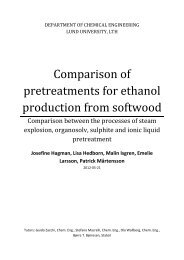
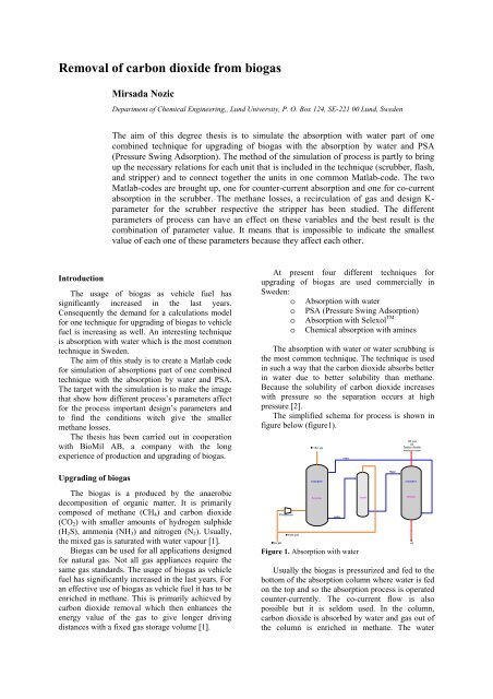
The simplified schema for process is shown in<br />
figure below (figure1).<br />
Figure 1. Absorption with water<br />
Usually the <strong>biogas</strong> is pressurized and fed to the<br />
bottom <strong>of</strong> the absorption column where water is fed<br />
on the top and so the absorption process is operated<br />
counter-currently. The co-current flow is also<br />
possible but it is seldom used. In the column,<br />
<strong>carbon</strong> <strong>dioxide</strong> is absorbed by water and gas out <strong>of</strong><br />
the column is enriched in methane. The water
which exits the column wits absorbed <strong>carbon</strong><br />
<strong>dioxide</strong> and a smaller amount <strong>of</strong> methane which is<br />
partly soluble in water leads to the flash tank there<br />
the gas is regenerated by de-pressuring and returned<br />
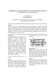
to the absorption column. The regeneration <strong>of</strong> water<br />
Figur 2. Process schema <strong>of</strong> the upgrading plant with Absorption with water and PSA<br />
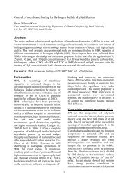
Water scrubbing can be used for the removal <strong>of</strong><br />
hydrogen sulphide since hydrogen sulphide is also<br />
soluble in water.<br />
Modeling <strong>of</strong> ‘Absorption with water’ - process<br />
Absorption with water is purely physical<br />
process. It means that it is the absorption without<br />
chemical reaction. The mass transfer <strong>from</strong> the gas<br />
to the liquid phase can be described by the two film<br />
theory. It is the approximated model which always<br />
assume the steady state, but because the simply<br />
mathematics expressions it is relatively easy to<br />
understand and it give the good accuracy.<br />
According to the two film theory the resistance to<br />
the mass transfer can describes with one or two<br />
stagnant films, the gas and the liquid film. Because<br />
the solubility <strong>of</strong> the gas follows the Henry’s law<br />
and Henry’s constant <strong>of</strong> <strong>carbon</strong> <strong>dioxide</strong> is large, it<br />
means that the solubility <strong>of</strong> <strong>carbon</strong> <strong>dioxide</strong> is small<br />
and concentration gradient in the liquid phase is<br />
large. According to the two films theory it result in<br />
that the significant resistance for the mass transfer<br />
is in the liquid phase and the gas film resistance and<br />
gas film itself can be neglected. If the process is<br />
controlled by the rate <strong>of</strong> mean transfer through the<br />
liquid film, such system is called for liquid phase<br />
controlled system.<br />
With these conditions, the total transfer rate <strong>of</strong><br />
the component A (methane) respective component<br />
is made by stripping with air in the desorption<br />
column, the stripper. Apart <strong>from</strong> <strong>carbon</strong> <strong>dioxide</strong>,<br />
the gas which exits the stripper contains methane<br />
losses [2].<br />
B (<strong>carbon</strong> <strong>dioxide</strong>) <strong>from</strong> the gas to the liquid phase<br />
in the differential volume at the absorption column<br />
(scrubber) is described by equation (1) and (2).<br />
⎛ FA<br />
⎜ ⋅ p<br />
dFA 0 ⎜ FA<br />
+ FB<br />
= k AL ⋅ a ⋅<br />
dV ⎜ H A<br />
⎜<br />
⎝<br />
⎛ FB<br />
⎜ ⋅ p<br />
dFB 0 ⎜ FA<br />
+ FB<br />
= k BL ⋅ a ⋅<br />
dV ⎜ H B<br />
⎜<br />
⎝<br />
tot<br />
tot<br />
⎞<br />
⎟<br />
FA<br />
− FAt<br />
+ C At ⋅ QL<br />
−<br />
⎟<br />
Q ⎟<br />
L<br />
⎟<br />
⎠<br />
⎞<br />
⎟<br />
FB<br />
− FBt<br />
+ CBt<br />
⋅Q<br />
L<br />
−<br />
⎟<br />
Q ⎟<br />
L<br />
⎟<br />
⎠<br />
(1)<br />
(2)<br />
In order the modeling <strong>of</strong> flash tank requires<br />
following equations (for the indexes see the<br />
nomenclature and the process schema in figure 2):<br />
y ⋅<br />
A ⋅ pT<br />
= C A H<br />
(3)<br />
2 A<br />
y ⋅<br />
B ⋅ pT<br />
= CB<br />
H<br />
(4)<br />
2 B<br />
( C A − C A2<br />
) ⋅ ( − y A ) = ( CB1<br />
− CB<br />
2 ) ⋅ y A<br />
1 1 (5)<br />
The stripper works as the convert scrubber and<br />
the total transfer rate <strong>of</strong> component A respective<br />
component B <strong>from</strong> the liquid to the gas phase in the<br />
differential volume at the desorption column is<br />
described by equation (6) and (7).
⎛<br />
⎜<br />
dFA 0<br />
= − ⋅ ⋅<br />
⎜ C<br />
k AL a<br />
dV<br />
⎜<br />
⎜<br />
⎝<br />
⎛<br />
⎜<br />
dFB 0<br />
= − ⋅ ⋅<br />
⎜ C<br />
k BL a<br />
dV ⎜<br />
⎜<br />
⎝<br />
ALt<br />
BLt<br />
FA<br />
⎞<br />
⋅ ptot<br />
⎟<br />
⋅Q<br />
L − FAt<br />
+ FA<br />
FA<br />
+ FB<br />
+ FC<br />
−<br />
⎟<br />
Q<br />
⎟<br />
L<br />
H A<br />
⎟<br />
⎠<br />
FB<br />
⎞<br />
⋅ ptot<br />
⎟<br />
⋅Q<br />
L − FBt<br />
+ FB<br />
FA<br />
+ FB<br />
+ FC<br />
−<br />
⎟<br />
Q<br />
⎟<br />
L<br />
H B<br />
⎟<br />
⎠<br />
(6)<br />
(7)<br />
It is assumed that the raw gas content only<br />
methane and <strong>carbon</strong> <strong>dioxide</strong>.<br />
Design parameter K<br />
Parameter K is introduced in the material<br />
balances for the scrubber and the stripper because<br />
the easily dimensioning <strong>of</strong> the columns. K is<br />
defined as<br />
dK = k AL ⋅ a ⋅ dV<br />
0 (8)<br />
Because the same parameter should be used for<br />
both methane and <strong>carbon</strong> <strong>dioxide</strong>, the rewriting <strong>of</strong><br />
the mass transfer coefficient <strong>of</strong> <strong>carbon</strong> <strong>dioxide</strong> is<br />
introduced. According to the turbulence model<br />
which is the most reliable empirical relation, the<br />
mass transfer coefficient for <strong>carbon</strong> <strong>dioxide</strong> can be<br />
written as<br />
k<br />
0<br />
BL<br />
= k<br />
0<br />
AL<br />
2<br />
3<br />
⎛ D ⎞ B ⋅<br />
⎜<br />
⎟<br />
⎝ DA<br />
⎠<br />
(9)<br />
With the value <strong>of</strong> diffusivities at 20°C the<br />
following relation is received<br />
0<br />
0<br />
k = . 09⋅<br />
k<br />
(10)<br />
BL<br />
1 AL<br />
The material balances for methane and <strong>carbon</strong><br />
<strong>dioxide</strong> in the counter-currently scrubber can be<br />
written as<br />
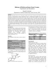
Figure 3. The block schema for the simulations input and received parameters<br />
⎛ FA<br />
⎜ ⋅ p<br />
dFA<br />
⎜ FA<br />
+ FB<br />
=<br />
dK ⎜ H A<br />
⎜<br />
⎝<br />
tot<br />
⎛ FB<br />
⎜ ⋅ p<br />
dFB<br />
⎜ FA<br />
+ FB<br />
= 1.<br />
09 ⋅<br />
dK ⎜ H B<br />
⎜<br />
⎝<br />
⎞<br />
⎟<br />
FA<br />
− FAt<br />
+ C At ⋅ QL<br />
−<br />
⎟<br />
Q ⎟<br />
L<br />
⎟<br />
⎠<br />
tot<br />
⎞<br />
⎟<br />
FB<br />
− FBt<br />
+ CBt<br />
⋅Q<br />
L<br />
−<br />
⎟<br />
Q ⎟<br />
L<br />
⎟<br />
⎠<br />
(11)<br />
(12)<br />
With the same reasoning, parameter K is<br />
introduced in the material balances <strong>of</strong> the stripper.<br />
Numerical solution <strong>of</strong> the model<br />
In the numerical solution or the simulation <strong>of</strong><br />
the process model, the each unit that is included in<br />
the technique (scrubber, flash, and stripper), is<br />
connected together in one common Matlab-code.<br />
The two Matlab-codes are brought up, one for<br />
counter current absorption and one for cocurrent<br />
absorption in the scrubber. The gas recirculation<br />
<strong>from</strong> the PSA and the dryer is added to the code as<br />
the constant percent <strong>of</strong> the gas which enter the unit.<br />
The Matlab-code is iterated until the system is<br />
converged.<br />
The simulation begins with input <strong>of</strong> the different<br />
process parameters which the user inputs <strong>from</strong> the<br />
keyboard. The block schema that shows which<br />
parameters has been inputted and which parameters<br />
are received, is presented in the figure 3.
Result<br />
The important variables to study are the loss <strong>of</strong><br />
methane, a recirculation <strong>of</strong> gas and design<br />
parameter K for the scrubber respective the stripper.<br />
The loss <strong>of</strong> methane is important both <strong>from</strong> the<br />
economic and the environment point <strong>of</strong> view. For<br />
these reasons it is necessary to keep it as low as<br />
possible. The different parameters <strong>of</strong> process can<br />
have an effect on these variables. The base case is<br />
chosen and one parameter at a time is varied and its<br />
effect is studied. The process’s parameters that can<br />
be varied are the liquid (water) flow, the pressure in<br />
the flash tank, the air flow in the stripper, the<br />
amount <strong>of</strong> stripped <strong>carbon</strong> <strong>dioxide</strong>, and the amount<br />
<strong>of</strong> absorbed methane for counter current absorption,<br />
and the methane fraction in the gas out <strong>of</strong> the<br />
scrubber for cocurrent absorption.<br />
The influence <strong>of</strong> the pressure in the flash tank<br />
on the methane losses and the recirculation <strong>of</strong> the<br />
gas for the counter current absorption are shown in<br />
diagram below (figure 4 and 5).<br />
Methane losses (%)<br />
6<br />
5<br />
4<br />
3<br />
2<br />
1<br />
0<br />
3 4 5 6 7 8<br />
P flash (bar)<br />
Figure 4. The influence <strong>of</strong> the pressure in flash tank on<br />
the methane losses<br />
Recirculation <strong>of</strong> gas (%)<br />
60<br />
55<br />
50<br />
45<br />
40<br />
35<br />
30<br />
25<br />
3 4 5 6 7<br />
P flash (bar)<br />
Figure 5. The influence <strong>of</strong> the pressure in flash tank on<br />
the recirculation <strong>of</strong> gas<br />
It is important to have the low water flow, the<br />
low flash pressure, and to strip the smaller amount<br />
<strong>of</strong> <strong>carbon</strong> <strong>dioxide</strong> to reduce the loss <strong>of</strong> methane. It<br />
is impossible to indicate the smallest value <strong>of</strong> each<br />
one <strong>of</strong> these parameters because they affect each<br />
other, e.g. extremely low flash pressure demands<br />
larger water flow. In other words, it is important to<br />
find a combination <strong>of</strong> the parameter values that will<br />
give the best answer. The best result with regard to<br />
the methane losses is 0.5 % for the counter current<br />
absorption and 0.9 % for the cocurrent absorption<br />
for the process that has been the basis <strong>of</strong> this thesis<br />
with the raw gas flow <strong>of</strong> 360 Nm 3 /h.<br />
Conclusion<br />
The choice <strong>of</strong> the process’s parameter values<br />
has some limitations. The minimum liquid flow is<br />
controlled by the conditions which should been<br />
filled, the amount <strong>of</strong> absorbed methane for the<br />
counter current absorption and the methane fraction<br />
in the gas out <strong>of</strong> the scrubber for cocurrent<br />
absorption. If the liquid flow is too small, the<br />
condition can not been filled and no response for<br />
the Kscrubber is determined.<br />
The pressure in the flash tank is controlled by<br />
the liquid flow and recirculation <strong>of</strong> gas. The<br />
extremely low pressure demands larger liquid flow<br />
and larger recirculation <strong>of</strong> gas.<br />
The methane losses increase with the amount <strong>of</strong><br />
striped <strong>carbon</strong> <strong>dioxide</strong> because the Kstripper is<br />
increased and with it, the amount <strong>of</strong> striped<br />
methane is also increased.<br />
Over- respective under dimensioned scrubber<br />
can be simple regulated by the change <strong>of</strong> the<br />
amount <strong>of</strong> absorbed methane for the counter current<br />
absorption and the methane fraction in the gas out<br />
<strong>of</strong> the scrubber for cocurrent absorption. The<br />
regulation <strong>of</strong> the stripper is preformed by the<br />
amount <strong>of</strong> striped <strong>carbon</strong> <strong>dioxide</strong>.<br />
In other words, it is important to find the<br />
combination <strong>of</strong> the process’s parameter values<br />
which will give the best answer for the variable<br />
which is more interesting to keep as low as<br />
possible.<br />
Nomenclature<br />
A<br />
B<br />
Methane (CH4)<br />
Carbon <strong>dioxide</strong> (CO2)<br />
C Air<br />
G Gas phase<br />
L Liquid phase<br />
0<br />
System<br />
reaction<br />
without the chemical<br />
t Top <strong>of</strong> column<br />
b Bottom <strong>of</strong> column<br />
0<br />
k L Mass transfer coefficient, m/s<br />
F Molar rate <strong>of</strong> gas, mol/s<br />
QL Liquid rate, m 3 /s<br />
V Volume <strong>of</strong> the column, m 3<br />
a Specific surface area , m 2 /m 3<br />
Ci Molar concentration <strong>of</strong> component<br />
i, mol/m 3
D Diffusion coefficient, m 2 /s<br />
HA Henry’s constant, Pa m 3 /mol<br />
K Design variabel, s/m 3<br />
ptot, pT Total pressure, Pa<br />
yi Mol fraction <strong>of</strong> component i in the<br />
gas phase, dimensionless<br />
References<br />
[1] Jarvis, Å. (2004) Biogas – renewable energy <strong>from</strong><br />
organic waste, The Swedish Biogas Association,<br />
Stockholm<br />
[2] Dahl, A. (2003) Quality fuse <strong>of</strong> <strong>biogas</strong> as the vehicle<br />
fuel, Swedish Gas Centre AB (SGC), Rapport 138,<br />
Malmö<br />
Received for review February 08, 2006