tj®-shear panel - Florida Building Code Information System
tj®-shear panel - Florida Building Code Information System
tj®-shear panel - Florida Building Code Information System

You also want an ePaper? Increase the reach of your titles
YUMPU automatically turns print PDFs into web optimized ePapers that Google loves.
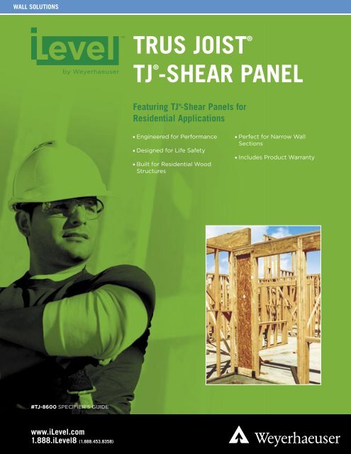
WALL SOLUTIONS<br />
#TJ-8600 SPECIFIER’S GUIDE<br />
www.iLevel.com<br />
1.888.iLevel8 (1.888.453.8358)<br />
TRUS JOIST ®<br />
TJ ®<br />
-SHEAR PANEL<br />
Featuring TJ ® -Shear Panels for<br />
Residential Applications<br />
Engineered for Performance<br />
Designed for Life Safety<br />
Built for Residential Wood<br />
Structures<br />
Perfect for Narrow Wall<br />
Sections<br />
Includes Product Warranty
TABLE OF CONTENTS<br />
2<br />
Life Safety Design 4–5<br />
Standard TJ ® -Shear Panels 6–7<br />
Engineered for Performance<br />
Design Load Table<br />
Raised Floor Kit 8–9<br />
Raised Floor Kit Installation<br />
Design Load Tables<br />
Portals 10–11<br />
Portal Installation<br />
Design Load Table<br />
Portal Header <strong>Information</strong><br />
Vertical Load Design Info. 12<br />
Garage Portal Configuration 13<br />
Sizing Tables Based on Wind 14–15<br />
7' Tall Garage Portals<br />
8' Tall Garage Portals<br />
Installation Details 16–19<br />
TJ ® -SHEAR PANEL<br />
WHY CHOOSE<br />
TJ ®<br />
-SHEAR PANEL?<br />
Shear Panels save lives and minimize home damage.<br />
We know from forensics and the historic performance of<br />
wood frame homes during earthquakes and hurricanes<br />
that wood <strong>shear</strong> <strong>panel</strong>s save lives and minimize<br />
home damage. The TJ ® -Shear <strong>panel</strong> has captured this<br />
performance in a pre-built <strong>panel</strong> with narrow widths<br />
(high aspect ratio) that allows you greater architectural<br />
freedom.<br />
The TJ ® -Shear <strong>panel</strong> installs quickly and simply.<br />
Plus, it incorporates all of the unique advantages of<br />
TimberStrand ® LSL—helping to minimize bowing,<br />
shrinking, and twisting—making it the product of choice<br />
for specifiers and engineers.<br />
To learn more about the properties that contribute to life<br />
safety, see the TJ ® -Shear <strong>panel</strong> Balanced Design<br />
information on page 4. Most TJ ® -Shear <strong>panel</strong>s are also<br />
ICC ES code-accepted.<br />
iLevel Trus Joist TJ ® -Shear Panel Specifier’s Guide TJ-8600 June 2006
1<br />
1<br />
3<br />
TJ ® -Shear Panel <strong>Code</strong> Evaluation: ICC-ES ESR-1281<br />
iLevel Trus Joist TJ ® -Shear Panel Specifier’s Guide TJ-8600 June 2006<br />
2<br />
2<br />
ARCHITECTURAL FREEDOM<br />
3<br />
3
LIFE SAFETY DESIGN<br />
TJ ® -Shear Panel Balanced Design<br />
The outstanding performance of TJ ® -Shear <strong>panel</strong>s comes from a balanced design<br />
approach. As with any traditional wood <strong>shear</strong> wall, four critical performance measures<br />
must each be maximized while not compromising the performance of the others.<br />
These four performance measures are:<br />
The allowable load is the amount of force a <strong>shear</strong><br />
wall can withstand during a lateral event, such<br />
as an earthquake or hurricane. This measure is<br />
determined using information from a “backbone<br />
curve” that includes load-carrying capacity and displacement<br />
limitations. Allowable loads are based on empirical<br />
tests and follow industry and ICC-accepted methods<br />
(AC 130).<br />
Damping is the ability of the <strong>shear</strong><br />
wall to remove lateral load or energy<br />
in a controlled, predictable manner.<br />
Panels with damping characteristics<br />
act like the shock absorbers in your<br />
car—absorbing energy during movement. TJ ® -Shear<br />
<strong>panel</strong>s dampen energy similar to site-built <strong>shear</strong> walls, ensuring<br />
consistent, controlled performance during seismic events.<br />
4<br />
Load (lbs)<br />
Ductility<br />
Ductility =<br />
Displacement (in.)<br />
∆ fail<br />
∆ yield<br />
iLevel Trus Joist TJ ® -Shear Panel Specifier’s Guide TJ-8600 June 2006<br />
Ductility is the measure of a member’s ability<br />
to resist loads even while experiencing large<br />
movements that are outside the elastic range of<br />
the <strong>shear</strong> <strong>panel</strong>, like those caused by earthquakes.<br />
This attribute increases life safety by helping the structure to<br />
remain standing during large displacements.<br />
The TJ ® -Shear <strong>panel</strong> has excellent ductility in a<br />
reduced wall width while performing similarly to<br />
standard-size, site-built <strong>shear</strong> walls.<br />
Stiffness is a measure of the<br />
deflection of a member under<br />
allowable loads—the stiffer a wall<br />
or <strong>panel</strong> is, the less it will deflect<br />
under load. Ideally, a wall is stiff enough to<br />
resist lateral loads and avoid excessive damage<br />
to finishes, windows, and other building elements, and yet should<br />
be flexible enough to avoid collecting too much energy and failing<br />
prematurely. The stiffness of TJ ® -Shear <strong>panel</strong>s is similar to sitebuilt<br />
<strong>shear</strong> walls which balances stiffness in the structure.
iLevel Trus Joist TJ ® -Shear Panel Specifier’s Guide TJ-8600 June 2006<br />
LIFE SAFETY DESIGN<br />
R Factor<br />
The response modification factor—the “R” factor—describes the ability of a structural<br />
element to perform compatibly with the surrounding structure. The R factor has three<br />
main components: ductility, damping, and redundancy. These properties allow for<br />
earthquake design loads to be reduced to a manageable level.<br />
Typically, it is not economical to design residential structures<br />
to resist maximum earthquake forces without damage. When<br />
design seismic forces are beyond the elastic range of the<br />
resisting elements in a structure, these elements should be<br />
designed to significantly deform (ductility) and effectively<br />
dissipate energy (damping) without collapse. Based on<br />
historical performance, the redundancy of structural elements<br />
in residential construction enhances the structure’s ability to<br />
withstand seismic forces.<br />
It is important for TJ ® -Shear <strong>panel</strong>s to have the same R<br />
factor as conventionally built, wood, <strong>shear</strong><br />
walls. Having the same R factor<br />
allows designers to mix and match<br />
site-built and prefabricated <strong>shear</strong><br />
<strong>panel</strong>s in a structure. This<br />
provides the greatest<br />
flexibility and cost<br />
savings while keeping life<br />
safety in mind. Multiple<br />
<strong>shear</strong> <strong>panel</strong>s provide<br />
greater redundancy too.<br />
All this allows the designer to<br />
develop only one set of design loads for an<br />
entire structure.<br />
More About “Balance”<br />
All TJ ® -Shear <strong>panel</strong> design properties are closely<br />
related. If one property is changed, the change affects<br />
all other properties. For example, raising the allowable<br />
load is likely to decrease drift capacity (the amount of<br />
deflection at failure) and ductility, reduce redundancy,<br />
and diminish seismic compatibility with the structure.<br />
TJ ®-Shear <strong>panel</strong>s are engineered with carefully<br />
designed connections and proprietary engineered-<br />
Exceeding the Elastic Range<br />
When high seismic forces cause a structure to<br />
deform beyond its elastic range into its inelastic<br />
range, serious failure can result. Northridge<br />
earthquake, 1994.<br />
wood components to produce the best property<br />
balance for resisting seismic loads in residential<br />
structures. With all of the advantages of traditional,<br />
site-built <strong>shear</strong> walls, plus a higher aspect ratio, TJ ® -<br />
Shear <strong>panel</strong>s allow more openings per wall and give you<br />
greater design flexibility than any other product on the<br />
market.<br />
5
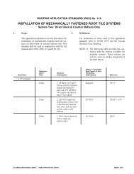
STANDARD TJ ® -SHEAR PANEL<br />
Engineered for Performance<br />
Concentric design of the <strong>panel</strong> and hold-down provides consistent performance<br />
that meets or exceeds traditional wood-framed <strong>shear</strong> walls.<br />
R Factor, Cd, and Ωo are consistent with typical wood-frame construction, which<br />
simplifies the design process.<br />
6<br />
3½"<br />
16" to 28"<br />
Panel Naming <strong>System</strong><br />
TJ 16x7<br />
Angled lags for easy installation<br />
Lag screw holes are pre-drilled at an angle for<br />
easy power tool access from below<br />
Resists bowing, twisting,<br />
and shrinking<br />
TimberStrand ® LSL rails and<br />
Performance Plus ® web resist bowing,<br />
twisting, and shrinking to make framing<br />
walls around the <strong>panel</strong> easy<br />
Pre-notched rail<br />
Pre-notched rail allows wire access<br />
through the lower half of the <strong>panel</strong><br />
Nominal height (ft)<br />
Width (in.)<br />
Trus Joist<br />
ICC-ES ESR-1281; complies with ICC-ES Acceptance Criteria for Prefabricated<br />
Wood Shear Panels (AC 130).<br />
May be used as an alternate braced-wall <strong>panel</strong> in accordance with UBC Section<br />
2320.11.3 and IBC Section 2308.9.3.1.<br />
For the City of Los Angeles, see TJ ® -Shear Panel for the City of Los Angeles,<br />
#R50-06, published by Weyerhaeuser.<br />
Convenient access for wiring<br />
Pre-drilled electrical access holes and<br />
concentric design allow for convenient<br />
wiring with shallow electrical boxes<br />
Simple connection<br />
Simple connection to the concrete<br />
foundation requires only two Trus Joist<br />
washers and standard nuts (included<br />
with <strong>panel</strong>). Slotted hold-downs allow<br />
maximum adjustability.<br />
For installation details, see pages 16–19.<br />
iLevel Trus Joist TJ ® -Shear Panel Specifier’s Guide TJ-8600 June 2006<br />
32" or 48"<br />
Field modification degrades<br />
performance. Do not drill additional<br />
holes or enlarge existing holes.
General Assumptions for TJ ® -Shear Panels<br />
TJ ® -Shear <strong>panel</strong>s are code-evaluated per ICC ES ESR-1281 and meet the<br />
acceptance criteria for prefabricated wood <strong>shear</strong> <strong>panel</strong>s (ICC-ES AC 130). They<br />
may be used as an alternate braced-wall <strong>panel</strong> in accordance with UBC section<br />
2320.11.4 and IBC section 2308.9.3.1.<br />
TJ ® -Shear <strong>panel</strong>s have design values consistent with typical wood-framed<br />
construction. Use the following ICC-ES-accepted values when designing with<br />
the prevailing code in your area:<br />
1997 UBC: R-value = 5.5; Ωo = 2.8<br />
2003 IBC: R-value = 6.5; Ωo = 3; Cd = 4<br />
Install products according to this guide. Modifications to this product and<br />
associated systems or changes in the installation methods should only be made<br />
by a qualified registered professional. Altered installation procedures and the<br />
performance of modified products are the sole responsibility of the designer.<br />
Refer to ICC ES ESR-1281 for further information.<br />
Allowable Design Loads (1) —Standard Panel on Concrete Foundation<br />
Model Width Height<br />
Ultimate<br />
In-Plane<br />
Shear Load<br />
(lbs)<br />
Hold-Down<br />
Anchor Uplift<br />
at Allowable<br />
Shear (4)(5)(6)<br />
(lbs)<br />
iLevel Trus Joist TJ ® -Shear Panel Specifier’s Guide TJ-8600 June 2006<br />
PANEL DESIGN LOAD TABLE<br />
The building shall be designed in accordance with the appropriate building code<br />
and meet local, state, and federal requirements. Verify design requirements with<br />
the local building department. Concrete design remains the responsibility of the<br />
designer or specifier.<br />
TJ ® -Shear <strong>panel</strong>s are part of the overall lateral-force-resisting system of the<br />
structure. Design of the building’s lateral-force-resisting system—including a<br />
complete load path necessary to transfer lateral-forces from the structure to the<br />
ground—is the responsibility of the designer or specifier.<br />
Use only code-minimum connections to attach sheathing or siding. If the<br />
connector will penetrate more than 1½" into the rail, place connectors as follows:<br />
– No more than 1½" from <strong>panel</strong> edge.<br />
– Only within the center ½" of the inside rail on a 32" or 48" <strong>panel</strong>.<br />
Values for 1997 UBC (2) Values for 2000, 2003 IBC (3)<br />
Allowable<br />
In-Plane<br />
Shear Load (6)<br />
(lbs)<br />
Drift at<br />
Allowable<br />
Shear Load<br />
(in.)<br />
Initial Panel<br />
Stiffness<br />
(lbs/in.)<br />
Hold-Down<br />
Anchor Uplift<br />
at Allowable<br />
Shear (4)(5)(6)<br />
(lbs)<br />
Allowable<br />
In-Plane<br />
Shear Load (6)<br />
(lbs)<br />
Drift at<br />
Allowable<br />
Shear Load<br />
(in.)<br />
Initial Panel<br />
Stiffness<br />
(lbs/in.)<br />
TJ16x7 16" 78" 4,093 6,800 1,220 0.34 3,635 6,600 1,185 0.32 3,655<br />
TJ22x7 22" 78" 6,127 8,445 2,165 0.35 6,170 8,230 2,110 0.34 6,200<br />
TJ16x8 16" 93¼" 3,847 7,000 1,050 0.43 2,465 6,830 1,025 0.41 2,470<br />
TJ18x8 18" 93¼" 4,461 7,460 1,280 0.40 3,205 7,230 1,240 0.39 3,205<br />
TJ20x8 20" 93¼" 5,153 8,550 1,650 0.39 4,210 8,290 1,600 0.38 4,230<br />
TJ22x8 22" 93¼" 5,976 8,770 1,880 0.39 4,825 8,540 1,830 0.38 4,850<br />
TJ24x8 24" 93¼" 5,777 8,395 1,980 0.38 5,190 8,200 1,935 0.37 5,210<br />
TJ28x8 28" 93¼" 6,999 9,800 2,730 0.38 7,205 9,550 2,660 0.37 7,250<br />
TJ32x8 32" 93¼" 8,603 9,950 3,200 0.37 8,575 9,730 3,130 0.36 8,625<br />
TJ48x8 48" 93¼" 12,526 11,130 5,490 0.35 15,890 10,960 5,390 0.34 16,050<br />
TJ16x9 16" 105¼" 3,476 5,870 780 0.47 1,650 5,640 750 0.45 1,655<br />
TJ18x9 18" 105¼" 4,998 7,730 1,175 0.48 2,445 7,500 1,140 0.46 2,455<br />
TJ20x9 20" 105¼" 4,422 7,660 1,310 0.46 2,850 7,430 1,270 0.45 2,855<br />
TJ24x9 24" 105¼" 5,278 8,755 1,830 0.45 4,075 8,490 1,775 0.43 4,080<br />
TJ28x9 28" 105¼" 6,483 9,680 2,390 0.44 5,405 9,440 2,330 0.43 5,430<br />
TJ32x9 32" 105¼" 7,678 9,805 2,795 0.44 6,405 9,560 2,725 0.42 6,440<br />
TJ48x9 48" 105¼" 11,404 10,525 4,600 0.38 12,075 10,525 4,600 0.38 12,170<br />
TJ18x10 18" 117¼" 3,357 6,890 940 0.51 1,860 6,670 910 0.49 1,865<br />
TJ20x10 20" 117¼" 4,334 8,210 1,260 0.50 2,510 8,020 1,230 0.49 2,515<br />
TJ24x10 24" 117¼" 5,119 9,330 1,750 0.49 3,565 9,070 1,700 0.47 3,585<br />
TJ28x10 28" 117¼" 5,951 9,790 2,170 0.49 4,440 9,520 2,110 0.47 4,455<br />
TJ32x10 32" 117¼" 7,357 10,220 2,615 0.48 5,490 10,005 2,560 0.46 5,530<br />
TJ48x10 48" 117¼" 9,803 10,960 4,300 0.43 9,920 10,970 4,300 0.43 9,995<br />
TJ24x12 24" 141¼" 4,115 8,160 1,270 0.60 2,105 7,900 1,230 0.58 2,115<br />
TJ28x12 28" 141¼" 5,018 9,240 1,700 0.60 2,830 8,970 1,650 0.58 2,845<br />
TJ32x12 32" 141¼" 5,791 9,660 2,050 0.58 3,555 9,420 2,000 0.56 3,575<br />
TJ48x12 48" 141¼" 8,084 10,450 3,400 0.56 6,070 10,200 3,320 0.54 6,110<br />
(1) No increases for duration-of-load are permitted.<br />
(2) R = 5.5.<br />
(3) R = 6.0 (2000 IBC) or 6.5 (2003 IBC), Cd of 4.0, IE of 1.0.<br />
(4) Hold-down anchors are 7 ⁄8" diameter ASTM A307 (minimum) rolled thread as designed<br />
by the engineer of record.<br />
(5) Hold-Down Anchor Uplift at Allowable Shear is based on an assumed moment-arm<br />
equal to the <strong>panel</strong> width minus 2".<br />
(6) Allowable In-Plane Shear Load must be considered in the hold-down anchor design.<br />
7
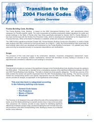
RAISED FLOOR KIT INSTALLATION<br />
Raised<br />
Floor Kit<br />
General Notes<br />
DO NOT modify the Raised Floor Kit. For floor assemblies of non-standard heights<br />
(floor <strong>panel</strong>s thicker than ¾", sill plates thicker than 1½", or floor joists different than<br />
standard TJI ® joist depths), adjust the total assembly height with shims at the top of<br />
the TJ ® -Shear Panel. Contact your Technical Representative for details.<br />
Place the Raised Floor Kit directly on the concrete. DO NOT place on top<br />
of the sill plate.<br />
The Raised Floor Kit may interrupt rim board continuity; design connections<br />
8<br />
as needed.<br />
RFK DIMENSIONS<br />
General Notes<br />
All kits use 3 ½" wide, 1.5E TimberStrand ® LSL<br />
blocks with pre-manufactured steel plates.<br />
For floor systems 9½" to 11 7 ⁄8" deep,<br />
– RFK height = joist height + 2¼"<br />
(assuming a 1½" sill plate and a ¾" floor <strong>panel</strong>)<br />
– RFK width = <strong>shear</strong> <strong>panel</strong> width + 3"<br />
For floor systems over 11 7 ⁄8" and up to 16" deep,<br />
contact your iLevel representative for dimensions<br />
and availability.<br />
Raised Floor Kit (RFK) Installation<br />
Thread coupler nuts and all-thread<br />
rods onto anchor bolts<br />
Lower block onto all-thread rods<br />
and swing bottom of block and<br />
spacer plates into place<br />
Install TJ ® -Shear Panel on block<br />
1 ⁄8" x 3 7 ⁄16" <strong>shear</strong> transfer plate<br />
(pre-attached)<br />
3½" 1.5E TimberStrand ® LSL<br />
block (shipped with kit)<br />
1 ⁄8" x 3 7 ⁄16" <strong>shear</strong> transfer<br />
plate (pre-attached)<br />
7 ⁄8" diameter all-thread rod (shipped with kit)<br />
7 ⁄8" x 2 7 ⁄16" ported coupler nut (shipped with kit)<br />
1 ⁄8" x 3 7 ⁄16" x 6" spacer plate (shipped with kit)<br />
7 ⁄8" cast-in-place anchor bolt<br />
Concrete foundation<br />
RFK<br />
height<br />
TimberStrand ® LSL<br />
rim board<br />
Concrete foundation<br />
(concrete design is the<br />
responsibility of the designer<br />
or specifier)<br />
1½"<br />
RFK width<br />
See General Assumptions on page 7.<br />
Shear<br />
transfer<br />
plate<br />
iLevel Trus Joist TJ ® -Shear Panel Specifier’s Guide TJ-8600 June 2006<br />
Interior View<br />
TJI ® hanger<br />
Ledger<br />
Floor <strong>panel</strong>, notched for RFK<br />
<strong>shear</strong> transfer plate<br />
Sill plate<br />
Sill plate anchor<br />
bolt (per code)<br />
TJI ® joist<br />
Attach floor joists to the RFK block using TJI ® joist hangers. Alternatively,<br />
joists may rest on the remaining sill plate if adequate bearing is available.<br />
Notch floor <strong>panel</strong>s around RFK block and TJ ® -Shear Panel. Support the<br />
floor <strong>panel</strong> with a ledger attached directly to the block or TJ ® -Shear Panel<br />
(depending on elevation requirements) to accommodate vertical loads and<br />
lateral load transfer. Contact your Technical Representative for details.<br />
Make sure that the bottom of the TJ ® -Shear Panel is in direct contact with<br />
the top <strong>shear</strong> transfer plate of the Raised Floor Kit. Compressible materials<br />
in this area will affect the performance of the assembly.<br />
3½"<br />
2 3 ⁄8"<br />
3½"<br />
Kit Naming <strong>System</strong><br />
TJ ® -Shear Panel RFK 9½ x 18<br />
Panel Width (in.)<br />
Floor Joist Depth (in.)<br />
Trus Joist Raised Floor Kit
Allowable Design Loads (1) —Standard Panel on Raised Floor Kit<br />
(For floor systems 11 7 ⁄8" deep or less)<br />
Model (4) Width Height<br />
Allowable Design Loads (1) —Standard Panel on Raised Floor Kit<br />
(For floor systems over 11 7 ⁄8" deep)<br />
Model Width Height<br />
Ultimate<br />
In-Plane<br />
Shear<br />
Load (lbs)<br />
Ultimate<br />
In-Plane<br />
Shear Load<br />
(lbs)<br />
Hold-Down<br />
Anchor Uplift<br />
at Allowable<br />
Shear (5)(6)(7)<br />
(lbs)<br />
Hold-Down<br />
Anchor Uplift<br />
at Allowable<br />
Shear (5)(6)(7)<br />
(lbs)<br />
RAISED FLOOR KIT DESIGN LOAD TABLES<br />
Values for 1997 UBC (2) Values for 2000, 2003 IBC (3)<br />
Allowable<br />
In-Plane<br />
Shear Load (7)<br />
(lbs)<br />
Drift at<br />
Allowable<br />
Shear Load<br />
(in.)<br />
Initial Panel<br />
Stiffness<br />
(lbs/in.)<br />
Hold-Down<br />
Anchor Uplift<br />
at Allowable<br />
Shear (5)(6)(7)<br />
(lbs)<br />
iLevel Trus Joist TJ ® -Shear Panel Specifier’s Guide TJ-8600 June 2006<br />
Allowable<br />
In-Plane<br />
Shear Load (7)<br />
(lbs)<br />
Drift at<br />
Allowable<br />
Shear Load<br />
(in.)<br />
Initial Panel<br />
Stiffness<br />
(lbs/in.)<br />
TJ16x8 16" 93¼" 3,845 6,440 850 0.40 2,130 6,250 825 0.39 2,130<br />
TJ18x8 18" 93¼" 4,460 7,010 1,055 0.40 2,650 6,810 1,025 0.39 2,655<br />
TJ20x8 20" 93¼" 5,155 7,450 1,260 0.40 3,175 7,240 1,225 0.38 3,190<br />
TJ22x8 22" 93¼" 5,975 7,800 1,465 0.40 3,700 7,590 1,425 0.38 3,720<br />
TJ24x8 24" 93¼" 5,775 8,090 1,670 0.40 4,230 7,870 1,625 0.38 4,255<br />
TJ28x8 28" 93¼" 7,000 8,530 2,080 0.39 5,305 8,310 2,025 0.38 5,330<br />
TJ32x8 32" 93¼" 8,605 8,860 2,490 0.39 6,385 8,630 2,425 0.38 6,430<br />
TJ48x8 48" 93¼" 12,525 9,620 4,135 0.38 10,880 9,360 4,025 0.37 10,940<br />
TJ16x9 16" 105¼" 3,475 6,330 750 0.46 1,650 6,120 725 0.44 1,650<br />
TJ18x9 18" 105¼" 5,000 6,980 945 0.45 2,085 6,800 920 0.44 2,100<br />
TJ20x9 20" 105¼" 4,420 7,500 1,140 0.45 2,530 7,300 1,110 0.44 2,545<br />
TJ24x9 24" 105¼" 5,280 8,270 1,535 0.45 3,435 8,030 1,490 0.43 3,450<br />
TJ28x9 28" 105¼" 6,485 8,810 1,930 0.44 4,355 8,560 1,875 0.43 4,380<br />
TJ32x9 32" 105¼" 7,680 9,180 2,320 0.44 5,285 8,950 2,260 0.42 5,330<br />
TJ48x9 48" 105¼" 11,405 10,060 3,890 0.42 9,195 9,800 3,790 0.41 9,290<br />
TJ18x10 18" 117¼" 3,355 6,840 840 0.51 1,655 6,590 810 0.49 1,655<br />
TJ20x10 20" 117¼" 4,335 7,460 1,030 0.51 2,040 7,210 995 0.49 2,045<br />
TJ24x10 24" 117¼" 5,120 8,310 1,400 0.50 2,800 8,070 1,360 0.48 2,825<br />
TJ28x10 28" 117¼" 5,950 8,920 1,775 0.49 3,595 8,700 1,730 0.48 3,635<br />
TJ32x10 32" 117¼" 7,355 9,370 2,150 0.49 4,395 9,130 2,095 0.47 4,455<br />
TJ48x10 48" 117¼" 9,805 10,380 3,645 0.47 7,820 10,140 3,560 0.45 7,945<br />
(1) No increases for duration-of-load are permitted.<br />
(2) R = 5.5 (UBC).<br />
(3) R = 6.0 (2000 IBC) or 6.5 (2003 IBC), Cd of 4.0, IE of 1.0.<br />
(4) Panel values apply to Raised Floor Kit floor-joist depths of 9½" and 11 7 ⁄8"<br />
(5) Hold-down anchors are 7 ⁄8" diameter ASTM A307 (minimum) rolled thread as designed<br />
by the engineer of record.<br />
(6) Hold-Down Anchor Uplift at Allowable Shear equals the uplift generated from the <strong>shear</strong><br />
Values for 1997 UBC (2) Values for 2000, 2003 IBC (3)<br />
Allowable<br />
In-Plane<br />
Shear Load (7)<br />
(lbs)<br />
Drift at<br />
Allowable<br />
Shear Load<br />
(in.)<br />
Initial Panel<br />
Stiffness<br />
(lbs/in.)<br />
Hold-Down<br />
Anchor Uplift<br />
at Allowable<br />
Shear (5)(6)(7)<br />
(lbs)<br />
Allowable<br />
In-Plane<br />
Shear Load (7)<br />
(lbs)<br />
Drift at<br />
Allowable<br />
Shear Load<br />
(in.)<br />
Initial Panel<br />
Stiffness<br />
(lbs/in.)<br />
TJ16x8 16" 93¼" 3,845 7,270 960 0.41 2,360 7,010 925 0.39 2,380<br />
TJ18x8 18" 93¼" 4,460 7,870 1,185 0.40 2,940 7,600 1,145 0.39 2,975<br />
TJ20x8 20" 93¼" 5,155 8,300 1,405 0.40 3,520 8,070 1,365 0.38 3,585<br />
TJ22x8 22" 93¼" 5,975 8,680 1,630 0.40 4,125 8,440 1,585 0.38 4,205<br />
TJ24x8 24" 93¼" 5,775 8,960 1,850 0.39 4,745 8,720 1,800 0.37 4,825<br />
TJ28x8 28" 93¼" 7,000 9,410 2,295 0.38 6,010 9,190 2,240 0.37 6,135<br />
TJ32x8 32" 93¼" 8,605 9,750 2,740 0.37 7,325 9,520 2,675 0.36 7,495<br />
TJ48x8 48" 93¼" 12,525 10,510 4,520 0.34 13,295 10,290 4,425 0.33 13,615<br />
TJ16x9 16" 105¼" 3,475 6,410 760 0.45 1,675 6,160 730 0.48 1,525<br />
TJ18x9 18" 105¼" 5,000 7,320 990 0.45 2,195 7,060 955 0.48 2,005<br />
TJ20x9 20" 105¼" 4,420 8,020 1,220 0.45 2,715 7,790 1,185 0.47 2,505<br />
TJ24x9 24" 105¼" 5,280 9,050 1,680 0.44 3,790 8,810 1,635 0.47 3,495<br />
TJ28x9 28" 105¼" 6,485 9,770 2,140 0.44 4,895 9,520 2,085 0.46 4,505<br />
TJ32x9 32" 105¼" 7,680 10,290 2,600 0.43 6,030 10,040 2,535 0.46 5,535<br />
TJ48x9 48" 105¼" 11,405 11,500 4,445 0.41 10,895 11,240 4,345 0.44 9,945<br />
TJ18x10 18" 117¼" 3,355 6,470 795 0.50 1,590 6,270 770 0.57 1,360<br />
TJ20x10 20" 117¼" 4,335 7,500 1,035 0.50 2,080 7,240 1,000 0.57 1,765<br />
TJ24x10 24" 117¼" 5,120 8,960 1,510 0.50 3,050 8,720 1,470 0.56 2,610<br />
TJ28x10 28" 117¼" 5,950 9,980 1,985 0.49 4,035 9,720 1,935 0.56 3,450<br />
TJ32x10 32" 117¼" 7,355 10,740 2,465 0.49 5,040 10,460 2,400 0.56 4,300<br />
TJ48x10 48" 117¼" 9,805 12,440 4,370 0.48 9,180 12,130 4,260 0.55 7,760<br />
<strong>panel</strong> plus the uplift generated from the raised floor kit, and is based on the following<br />
assumptions:<br />
Panel: moment arm = <strong>panel</strong> width minus 2"<br />
Raised Floor Kit: tallest applicable kit, see page 8<br />
moment arm = block width minus 3½"<br />
Uplift numbers do not include any consideration of <strong>shear</strong> from the first floor<br />
diaphragms; this check is the responsibility of the designer or specifier.<br />
(7) Allowable In-Plane Shear Load must be considered in the hold-down anchor design.<br />
9
PORTAL INSTALLATION<br />
Header. See<br />
Portal Frame<br />
Header Design<br />
on page 11.<br />
Pre-drilled<br />
electrical access<br />
holes<br />
10<br />
3½"<br />
Hold-down<br />
Panel Naming <strong>System</strong><br />
TJ 16x7<br />
Nominal height (ft)<br />
Width (in.)<br />
Trus Joist<br />
Double Portal (D)<br />
Beam clear span,<br />
18'-6" maximum<br />
Pre-notched<br />
electrical access<br />
Concrete design is<br />
the responsibility<br />
of the designer or<br />
specifier<br />
Field modification<br />
degrades performance.<br />
Do not drill additional holes<br />
or enlarge existing holes.<br />
Portal straps ¼" from edges<br />
on both sides of the <strong>panel</strong> (4<br />
straps total per <strong>panel</strong>)<br />
Top block pre-drilled for<br />
USP WS6 lag screws (or<br />
equivalent)<br />
TimberStrand ® LSL rail<br />
Performance Plus ® web<br />
TimberStrand ® LSL<br />
base block<br />
Header. See Portal Frame<br />
Header Design on page 11.<br />
Portal straps ¼" from edges on<br />
both sides of the column<br />
(2 straps total)<br />
1.5E TimberStrand ® LSL<br />
portal column<br />
iLevel Trus Joist TJ ® -Shear Panel Specifier’s Guide TJ-8600 June 2006<br />
3½"<br />
Single Portal (S)<br />
Electrical access holes are pre-drilled<br />
for your convenience. No additional<br />
access holes are allowed.<br />
4 3 ⁄8"<br />
General Notes<br />
Panels can be used with<br />
4" or 6" nominal walls. Center <strong>panel</strong><br />
under header. See installation details<br />
SP1 and SP2 on page 16.<br />
Portal Panels are not for use in<br />
raised-floor applications.<br />
For shimming requirements, see<br />
detail SP7 on page 17.<br />
See General Assumptions on page 7.<br />
Beam clear span,<br />
18'-6" maximum<br />
3½"<br />
Pre-notched<br />
electrical access
Allowable Design Loads (1) —Garage Portal <strong>System</strong><br />
Portal<br />
Configuration<br />
Width Height<br />
Ultimate<br />
In-Plane<br />
Shear Load<br />
(lbs)<br />
Portal Frame Header Design<br />
Header depth must be minimum of 9¼" and a maximum of 18".<br />
Header design should consider vertical and lateral load combinations. Design header as a simple span with no end fixity.<br />
When lateral loads are present, add the induced forces shown in the table below.<br />
The TJ ® -Shear <strong>panel</strong> portal may use a header stiffness, Kbeam, of 90 lbs/in. to 4,000 lbs/in.<br />
Kbeam is defined as: Kbeam = Ebd<br />
where<br />
E = beam modulus of elasticity (psi)<br />
b = beam width (in.)<br />
d = beam depth (in.)<br />
L = beam clear span (in.) (18'-6" maximum)<br />
3<br />
12L3 Hold-Down<br />
Anchor Uplift<br />
at Allowable<br />
Shear (4)(5)(6)<br />
(lbs)<br />
(1) No increases for duration-of-load are permitted.<br />
(2) R = 5.5.<br />
(3) R = 6.0 or 6.5, Cd of 4.0, IE of 1.0<br />
(4) Hold-down anchors are 7 ⁄8" diameter ASTM A307 (minimum) rolled thread as designed by the engineer of record.<br />
(5) Hold-Down Anchor Uplift at Allowable Shear is based on an assumed moment arm equal to the <strong>panel</strong> width minus 2", and considers portal frame behavior.<br />
(6) Allowable In-Plane Shear Load must be considered in the hold-down anchor design.<br />
(7) Values shown are for the complete portal frame assembly.<br />
Maximum Induced Forces (1)(2) in the Header of Portal<br />
Frame <strong>System</strong>s<br />
Model Bending Moment (3) (ft-lbs)<br />
Shear<br />
(lbs)<br />
Axial Load<br />
(lbs)<br />
TJ16x7 or TJ22x7 2,110 960 2,630<br />
TJ16x8 or TJ22x8 2,900 960 2,065<br />
(1) Beam forces induced when the maximum allowable in-plane <strong>shear</strong> load for portal <strong>panel</strong>s is applied.<br />
(2) The maximum forces shown may be reduced linearly if the applied lateral <strong>shear</strong> load is less than the allowable inplane<br />
<strong>shear</strong> load.<br />
(3) For double portal systems, the moment decreases linearly from maximum at beam end to zero at mid-span. For single<br />
portal systems, the moment decreases linearly from maximum at the TJ ®-Shear <strong>panel</strong> end to zero at the column end.<br />
This induced moment must be included when designing the portal header.<br />
iLevel Trus Joist TJ ® -Shear Panel Specifier’s Guide TJ-8600 June 2006<br />
PORTAL DESIGN LOAD TABLE<br />
Values for 1997 UBC (2) Values for 2000, 2003 IBC (3)<br />
Allowable<br />
In-Plane<br />
Shear Load (6)<br />
(lbs)<br />
Drift at<br />
Allowable<br />
Shear Load<br />
(in.)<br />
Initial<br />
Panel<br />
Stiffness<br />
(lbs/in.)<br />
Hold-Down<br />
Anchor Uplift<br />
at Allowable<br />
Shear (4)(5)(6)<br />
(lbs)<br />
Allowable<br />
In-Plane<br />
Shear Load (6)<br />
(lbs)<br />
Drift at<br />
Allowable<br />
Shear Load<br />
(in.)<br />
Initial Panel<br />
Stiffness<br />
(lbs/in.)<br />
D TJ16x7 (7) 16" 78" 8,780 7,650 2,830 0.36 7,860 7,465 2,765 0.35 7,900<br />
D TJ22x7 (7) 22" 78" 11,760 9,680 4,855 0.37 13,300 9,415 4,725 0.35 13,375<br />
D TJ16x8 (7) 16" 93¼" 8,140 7,650 2,455 0.41 5,980 7,480 2,400 0.40 6,015<br />
D TJ22x8 (7) 22" 93¼" 12,295 8,820 4,015 0.40 9,990 8,790 4,000 0.40 10,025<br />
S TJ16x7 (7) 16" 78" 4,525 7,650 1,340 0.34 3,885 7,445 1,300 0.33 3,920<br />
S TJ22x7 (7) 22" 78" 6,100 9,680 2,395 0.37 6,525 9,395 2,325 0.35 6,565<br />
S TJ16x8 (7) 16" 93¼" 4,125 7,650 1,235 0.46 2,695 7,480 1,210 0.45 2,705<br />
S TJ22x8 (7) 22" 93¼" 6,230 8,820 2,065 0.43 4,785 8,820 2,065 0.43 4,805<br />
PORTAL HEADER INFORMATION<br />
11
VERTICAL LOAD DESIGN INFORMATION<br />
Vertical Load Design<br />
TJ ® -Shear <strong>panel</strong>s are designed to carry vertical loads in addition to in-plane <strong>shear</strong> loads. For vertical loads applied to the rails, use the Allowable Vertical Loads per Rail<br />
table. For vertical loads applied between the rails, use the Top Block Section Properties table.<br />
Allowable Vertical Loads per Rail (lbs) (1)<br />
Allowable Out-of-Plane Lateral Loads per Rail (PLF)<br />
Applied<br />
Vertical<br />
Load<br />
per<br />
Rail (1)<br />
(lbs)<br />
12<br />
Model<br />
With Design Shear (2)<br />
133% Load Duration<br />
Exterior<br />
Rail (2)<br />
Interior<br />
Rail (2)<br />
Single Portal<br />
Column<br />
TJ ® -Shear Panel<br />
Exterior<br />
Rail (3)<br />
Axial Load Only<br />
100% Load Duration<br />
Interior<br />
Rail (3)<br />
Single Portal<br />
Column<br />
TJ16x7 8,000 (4) – 7,830 (5) 8,000 (4) – 8,330 (5)<br />
TJ22x7 8,000 (4) – 7,830 (5) 8,000 (4) – 8,330 (5)<br />
TJ16x8 8,000 (4) – 7,830 (5) 8,000 (4) – 8,330 (5)<br />
TJ18x8 7,410 – – 8,000 – –<br />
TJ20x8 7,990 – – 8,000 – –<br />
TJ22x8 7,430 (4) – 7,830 (5) 8,000 (4) – 8,330 (5)<br />
TJ24x8 8,000 – – 8,000 – –<br />
TJ28x8 7,340 – – 8,000 – –<br />
TJ32x8 7,260 8,000 – 8,000 8,000 –<br />
TJ48x8 6,620 8,000 – 8,000 8,000 –<br />
TJ16x9 6,970 – – 8,000 – –<br />
TJ18x9 6,150 – – 8,000 – –<br />
TJ20x9 6,180 – – 8,000 – –<br />
TJ24x9 5,680 – – 8,000 – –<br />
TJ28x9 5,250 – – 8,000 – –<br />
TJ32x9 5,190 8,000 – 8,000 8,000 –<br />
TJ48x9 4,840 8,000 – 8,000 8,000 –<br />
TJ18x10 4,830 – – 7,350 – –<br />
TJ20x10 4,280 – – 7,350 – –<br />
TJ24x10 3,790 – – 7,350 – –<br />
TJ28x10 3,590 – – 7,350 – –<br />
TJ32x10 3,390 7,325 – 7,350 7,215 –<br />
TJ48x10 3,055 7,325 – 7,350 7,215 –<br />
TJ24x12 2,100 – – 5,030 – –<br />
TJ28x12 1,650 – – 5,030 – –<br />
TJ32x12 1,480 5,000 – 5,030 4,950 –<br />
TJ48x12 1,150 5,000 5,030 4,950<br />
(1) Maximum allowable axial loads with no out-of-plane lateral loads applied. For combined<br />
loading, see the table below. Vertical loads are based on <strong>shear</strong>-<strong>panel</strong> capacity; adjustments<br />
may be necessary for concrete-bearing design based on Fc' of 2,500 psi and the <strong>panel</strong>’s proximity<br />
to the edge. Refer to ACI 318-02, Section 10.17 for guidance.<br />
(2) Maximum axial compression that can be applied directly over a rail in combination with the<br />
full design <strong>shear</strong>.<br />
1.5E TimberStrand ® LSL<br />
Portal Column<br />
133% Load 160% Load<br />
Duration Duration<br />
133% Load<br />
Duration<br />
160% Load<br />
Duration<br />
Height Height Height Height<br />
78" 93¼" 105¼" 117¼" 141¼" 78" 93¼" 105¼" 117¼" 141¼" 78" 93¼" 78" 93¼"<br />
0 70 (2) 55 (3) 75 55 30 80 (2) 65 (3) 75 55 30 65 55 80 65<br />
2,000 115 (2) 95 (3) 75 55 30 125 (2) 105 (3) 75 55 30 110 90 120 100<br />
4,000 160 (2) 110 75 55 30 170 (2) 110 75 55 30 150 100 165 100<br />
6,000 205 110 75 35 0 205 110 75 50 0 180 100 180 100<br />
8,000 195 70 15 0 0 205 105 35 0 0 175 65 180 90<br />
(1) Value may be increased by a load duration factor.<br />
(2) 205 plf, if <strong>panel</strong> is not part of a portal frame system.<br />
(3) 110 plf, if <strong>panel</strong> is not part of a portal frame system.<br />
General Notes<br />
Applied vertical load per rail in the table is the load that acts in combination with the out-of-plane lateral loads.<br />
Verify that the maximum allowable vertical load per rail has not been exceeded. See table above.<br />
Table is based on:<br />
– TJ ® -Shear <strong>panel</strong>s used in a standard application or on a Raised Floor Kit and installed according to the details<br />
in this guide.<br />
– Wall deflection of L/240.<br />
– Maximum header depth of 18" Portal system application.<br />
iLevel Trus Joist TJ ® -Shear Panel Specifier’s Guide TJ-8600 June 2006<br />
Top Block Section Properties<br />
(100% Load Duration)<br />
A<br />
B<br />
A<br />
B<br />
A<br />
Exterior rail<br />
allowable vertical<br />
load<br />
Interior rail<br />
allowable<br />
vertical load<br />
A<br />
Top block<br />
allowable<br />
design stresses<br />
at notched<br />
sections<br />
Applied<br />
vertical load<br />
(lbs)<br />
Side View<br />
Exterior rail<br />
allowable<br />
vertical load<br />
B<br />
Top block<br />
allowable<br />
design stresses<br />
between rails<br />
Shear (lbs) 1,865 2,565<br />
Moment (in.-lbs) 10,290 14,150<br />
(3) Maximum axial compression that can be applied directly over a rail when no lateral loads<br />
are present. Allowable load may be increased by a load-duration factor, up to a maximum of<br />
8,000 lbs. per rail.<br />
(4) Axial compression for portal-system <strong>panel</strong> rails may not exceed 8,000 lbs. per <strong>panel</strong>.<br />
(5) Column values are for 3½" x 3½" 1.5E TimberStrand ® LSL. Axial compression may be<br />
increased by a load-duration factor, up to a maximum of 10,500 lbs.<br />
Out-ofplane<br />
lateral<br />
loads<br />
(PLF)
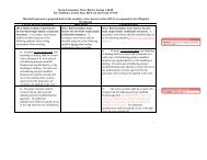
Panel Configurations at Garage<br />
(For use with sizing tables on pages 10 and 11)<br />
Opening<br />
Height<br />
One Single One Single<br />
One Double One Double<br />
Two Singles One Single and One Double<br />
Ensuring continuous lateral load paths is the responsibility of the<br />
designer. To transfer <strong>shear</strong> load across header joints, the use of<br />
horizontal steel straps on the front and back of the header joint,<br />
or use a double top plate with sufficient lap-splice length and<br />
nailing to resist load is recommended.<br />
Shear Capacities for TJ ® -Shear Panel Used in Garage Portals<br />
(For use with sizing tables on pages 14 and 15)<br />
7'<br />
8'<br />
Portal Configuration Description<br />
Shear Capacity<br />
(lbs)<br />
S TJ16x7 Single <strong>panel</strong> TJ16x7 1,300<br />
S TJ22x7 Single <strong>panel</strong> TJ22x7 2,325<br />
D TJ16x7 Double <strong>panel</strong> TJ16x7 2,765<br />
S TJ16x7 & S TJ22x7 TJ16x7 & TJ22x7 in Double <strong>panel</strong> or as 2 Singles 3,625<br />
S TJ16x7 & D TJ16x7 Single <strong>panel</strong> TJ16x7 + Double <strong>panel</strong> TJ16x7 4,065<br />
D TJ22x7 Double <strong>panel</strong> TJ22x7 4,725<br />
S TJ22x7 & D TJ16x7 Single <strong>panel</strong> TJ22x7 + Double <strong>panel</strong> TJ16x7 5,090<br />
S TJ16x7 & D TJ22x7 Single <strong>panel</strong> TJ16x7 + Double <strong>panel</strong> TJ22x7 6,025<br />
S TJ22x7 & D TJ22x7 Single <strong>panel</strong> TJ22x7 + Double <strong>panel</strong> TJ22x7 7,050<br />
S TJ16x8 Single <strong>panel</strong> TJ16x8 1,210<br />
S TJ22x8 Single <strong>panel</strong> TJ22x8 2,065<br />
D TJ16x8 Double <strong>panel</strong> TJ16x8 2,400<br />
S TJ16x8 & S TJ22x8 TJ16x8 & TJ22x8 in Double <strong>panel</strong> or as 2 Singles 3,275<br />
S TJ16x8 & D TJ16x8 Single <strong>panel</strong> TJ16x8 + Double <strong>panel</strong> TJ16x8 3,610<br />
D TJ22x8 Double <strong>panel</strong> TJ22x8 4,000<br />
S TJ22x8 & D TJ16x8 Single <strong>panel</strong> TJ22x8 + Double <strong>panel</strong> TJ16x8 4,465<br />
S TJ16x8 & D TJ22x8 Single <strong>panel</strong> TJ16x8 + Double <strong>panel</strong> TJ22x8 5,210<br />
S TJ22x8 & D TJ22x8 Single <strong>panel</strong> TJ22x8 + Double <strong>panel</strong> TJ22x8 6,065<br />
iLevel Trus Joist TJ ® -Shear Panel Specifier’s Guide TJ-8600 June 2006<br />
GARAGE PORTAL CONFIGURATION<br />
13
SIZING TABLES BASED ON WIND<br />
Garage Portal Panel Selection<br />
These tables are limited to garage fronts in one- and two-story residential dwellings. The <strong>panel</strong> solutions have been optimized for use as TJ ® -Shear Panel Portal Frames.<br />
For <strong>panel</strong> configurations and <strong>shear</strong> capacities of portal configurations, see page 9.<br />
TJ ® -Shear Panels for 7'-High Garage Door Openings<br />
1<br />
2<br />
3<br />
4<br />
14<br />
TJ ® -Shear Panel<br />
Condition<br />
TJ ® -Shear <strong>panel</strong>s<br />
L<br />
Wall<br />
Length,<br />
L<br />
Basic Garage Floor Plan<br />
36'<br />
Three Second Gust Wind Speed (MPH)<br />
85 90 100 110 120 130 140 150<br />
Minimum TJ ® -Shear Panel Portal Configuration<br />
18' S 16x7 S 16x7 S 16x7 S 16x7 S 22x7 S 22x7 S 22x7 S 22x7<br />
20' S 16x7 S 16x7 S 16x7 S 22x7 S 22x7 S 22x7 S 22x7 D 16x7<br />
22' S 16x7 S 16x7 S 16x7 S 22x7 S 22x7 S 22x7 D 16x7 S16x7 & S22x7<br />
24' S 16x7 S 16x7 S 22x7 S 22x7 S 22x7 S 22x7 D 16x7 S16x7 & S22x7<br />
26' S 16x7 S 16x7 S 22x7 S 22x7 S 22x7 D 16x7 S16x7 & S22x7 S16x7 & S22x7<br />
28' S 16x7 S 16x7 S 22x7 S 22x7 S 22x7 D 16x7 S16x7 & S22x7 S16x7 & S22x7<br />
30' S 16x7 S 22x7 S 22x7 S 22x7 D 16x7 S16x7 & S22x7 S16x7 & S22x7 S16x7 & D16x7<br />
32' S 22x7 S 22x7 S 22x7 S 22x7 D 16x7 S16x7 & S22x7 S16x7 & S22x7 S16x7 & D16x7<br />
34' S 22x7 S 22x7 S 22x7 S 22x7 D 16x7 S16x7 & S22x7 S16x7 & D16x7 D 22x7<br />
36' S 22x7 S 22x7 S 22x7 D 16x7 S16x7 & S22x7 S16x7 & S22x7 S16x7 & D16x7 D 22x7<br />
40' S 22x7 S 22x7 S 22x7 D 16x7 S16x7 & S22x7 S16x7 & D16x7 D 22x7 S22x7 & D16x7<br />
18' S 22x7 S 22x7 D 16x7 S16x7 & S22x7 S16x7 & S22x7 S16x7 & D16x7 D 22x7 S16x7 & D22x7<br />
20' S 22x7 S 22x7 D 16x7 S16x7 & S22x7 S16x7 & D16x7 D 22x7 S22x7 & D16x7 S16x7 & D22x7<br />
22' S 22x7 S 22x7 S16x7 & S22x7 S16x7 & S22x7 D 22x7 S22x7 & D16x7 S16x7 & D22x7 S22x7 & D22x7<br />
24' S 22x7 D 16x7 S16x7 & S22x7 S16x7 & D16x7 D 22x7 S16x7 & D22x7 S22x7 & D22x7 S22x7 & D22x7<br />
26' D 16x7 D 16x7 S16x7 & S22x7 D 22x7 S22x7 & D16x7 S16x7 & D22x7 S22x7 & D22x7<br />
28' D 16x7 S16x7 & S22x7 S16x7 & D16x7 D 22x7 S16x7 & D22x7 S22x7 & D22x7<br />
30' S16x7 & S22x7 S16x7 & S22x7 S16x7 & D16x7 D 22x7 S16x7 & D22x7 S22x7 & D22x7<br />
32' S16x7 & S22x7 S16x7 & S22x7 D 22x7 S22x7 & D16x7 S16x7 & D22x7 S22x7 & D22x7<br />
34' S16x7 & S22x7 S16x7 & S22x7 D 22x7 S16x7 & D22x7 S22x7 & D22x7<br />
36' S16x7 & S22x7 S16x7 & D16x7 D 22x7 S16x7 & D22x7 S22x7 & D22x7<br />
40' S16x7 & D16x7 D22x7 S16x7 & D22x7 S22x7 & D22x7<br />
18' S 16x7 S 16x7 S 16x7 S 16x7 S 16x7 S 22x7 S 22x7 S 22x7<br />
20' S 16x7 S 16x7 S 16x7 S 16x7 S 22x7 S 22x7 S 22x7 S 22x7<br />
22' S 16x7 S 16x7 S 16x7 S 22x7 S 22x7 S 22x7 S 22x7 D 16x7<br />
24' S 16x7 S 16x7 S 16x7 S 22x7 S 22x7 S 22x7 D 16x7 D 16x7<br />
26' S 16x7 S 16x7 S 16x7 S 22x7 S 22x7 S 22x7 D 16x7 S16x7 & S22x7<br />
28' S 16x7 S 16x7 S 22x7 S 22x7 S 22x7 D 16x7 D 16x7 S16x7 & S22x7<br />
30' S 16x7 S 16x7 S 22x7 S 22x7 S 22x7 D 16x7 S16x7 & S22x7 S16x7 & S22x7<br />
32' S 16x7 S 16x7 S 22x7 S 22x7 S 22x7 D 16x7 S16x7 & S22x7 S16x7 & S22x7<br />
34' S 16x7 S 22x7 S 22x7 S 22x7 D 16x7 S16x7 & S22x7 S16x7 & S22x7 S16x7 & D16x7<br />
36' S 16x7 S 22x7 S 22x7 S 22x7 D 16x7 S16x7 & S22x7 S16x7 & S22x7 S16x7 & D16x7<br />
40' S 22x7 S 22x7 S 22x7 D 16x7 S16x7 & S22x7 S16x7 & S22x7 S16x7 & D16x7 D 22x7<br />
18' S 22x7 S 22x7 S 22x7 S 22x7 D 16x7 S16x7 & S22x7 S16x7 & S22x7 D 22x7<br />
20' S 22x7 S 22x7 S 22x7 D 16x7 S16x7 & S22x7 S16x7 & S22x7 S16x7 & D16x7 D 22x7<br />
22' S 22x7 S 22x7 S 22x7 D 16x7 S16x7 & S22x7 S16x7 & D16x7 D 22x7 S22x7 & D16x7<br />
24' S 22x7 S 22x7 D 16x7 S16x7 & S22x7 S16x7 & S22x7 D 22x7 S22x7 & D16x7 S16x7 & D22x7<br />
26' S 22x7 S 22x7 D 16x7 S16x7 & S22x7 S16x7 & D16x7 D 22x7 S16x7 & D22x7 S16x7 & D22x7<br />
28' S 22x7 D 16x7 S16x7 & S22x7 S16x7 & S22x7 D 22x7 S22x7 & D16x7 S16x7 & D22x7 S22x7 & D22x7<br />
30' S 22x7 D 16x7 S16x7 & S22x7 S16x7 & D16x7 D 22x7 S16x7 & D22x7 S22x7 & D22x7 S22x7 & D22x7<br />
32' D 16x7 D 16x7 S16x7 & S22x7 S16x7 & D16x7 S22x7 & D16x7 S16x7 & D22x7 S22x7 & D22x7<br />
34' D 16x7 S16x7 & S22x7 S16x7 & S22x7 D 22x7 S22x7 & D16x7 S16x7 & D22x7 S22x7 & D22x7<br />
36' D 16x7 S16x7 & S22x7 S16x7 & D16x7 D 22x7 S16x7 & D22x7 S22x7 & D22x7<br />
40' S16x7 & S22x7 S16x7 & S22x7 D 22x7 S22x7 & D16x7 S16x7 & D22x7 S22x7 & D22x7<br />
Braced garage wall<br />
Roof ridge line (may run<br />
in either direction)<br />
Garage front<br />
See General Notes on page 11.<br />
Legend<br />
Single<br />
Width (in.)<br />
Nominal<br />
height (ft)<br />
iLevel Trus Joist TJ ® -Shear Panel Specifier’s Guide TJ-8600 June 2006<br />
Both <strong>panel</strong>s<br />
are required<br />
Width (in.)<br />
Double<br />
Nominal<br />
height (ft)
TJ ® -Shear Panels for 8'-High Garage Door Openings<br />
1<br />
2<br />
3<br />
4<br />
TJ ® -Shear Panel<br />
Condition<br />
General Notes<br />
Wall<br />
Length,<br />
L<br />
Applicable for one and two story buildings with gable and hipped roofs only.<br />
For hipped roofs, use profiles (1) and (2).<br />
Tables are based on:<br />
– ASCE 7-02, Method 2 Analysis Procedure Section 6.5<br />
– Loads per ASCE 7-02 & 2003 IBC, assuming exposure B<br />
– Topographic effect Kzt = 1<br />
– Partially enclosed building<br />
– ANSI/AF&PA Wood Frame Construction Manual Section 3<br />
– Exposure B<br />
– <strong>Building</strong> aspect ratio (L/W) shall not be less than 1:4 nor greater than 4:1<br />
– Mean roof height shall not exceed 33'<br />
– Roof slope of 6:12 or less. The attic area shall be considered an additional<br />
story when the roof slope is greater than 6:12. See Fig 3.1a of WFCM.<br />
– Wall height of 7' or 8'<br />
– Maximum building width of 36'<br />
– Adequate lateral bracing for the rear wall of the garage<br />
iLevel Trus Joist TJ ® -Shear Panel Specifier’s Guide TJ-8600 June 2006<br />
SIZING TABLES BASED ON WIND<br />
Three Second Gust Wind Speed (MPH)<br />
85 90 100 110 120 130 140 150<br />
Minimum TJ ® -Shear Panel Portal Configuration<br />
18' S 16x8 S 16x8 S 16x8 S 22x8 S 22x8 S 22x8 S 22x8 D 16x8<br />
20' S 16x8 S 16x8 S 16x8 S 22x8 S 22x8 S 22x8 D 16x8 S16x8 & S22x8<br />
22' S 16x8 S 16x8 S 22x8 S 22x8 S 22x8 D 16x8 S16x8 & S22x8 S16x8 & S22x8<br />
24' S 16x8 S 16x8 S 22x8 S 22x8 S 22x8 D 16x8 S16x8 & S22x8 S16x8 & S22x8<br />
26' S 16x8 S 16x8 S 22x8 S 22x8 D 16x8 S16x8 & S22x8 S16x8 & S22x8 S16x8 & D16x8<br />
28' S 16x8 S 22x8 S 22x8 S 22x8 D 16x8 S16x8 & S22x8 S16x8 & S22x8 S16x8 & D16x8<br />
30' S 22x8 S 22x8 S 22x8 S 22x8 S16x8 & S22x8 S16x8 & S22x8 S16x8 & D16x8 D 22x8<br />
32' S 22x8 S 22x8 S 22x8 D 16x8 S16x8 & S22x8 S16x8 & S22x8 S16x8 & D16x8 S22x8 & D16x8<br />
34' S 22x8 S 22x8 S 22x8 D 16x8 S16x8 & S22x8 S16x8 & S22x8 D 22x8 S22x8 & D16x8<br />
36' S 22x8 S 22x8 S 22x8 S16x8 & S22x8 S16x8 & S22x8 S16x8 & D16x8 D 22x8 S16x8 & D22x8<br />
40' S 22x8 S 22x8 D 16x8 S16x8 & S22x8 S16x8 & S22x8 D 22x8 S22x8 & D16x8 S16x8 & D22x8<br />
18' S 22x8 S 22x8 D 16x8 S16x8 & S22x8 S16x8 & D16x8 D 22x8 S16x8 & D22x8 S22x8 & D22x8<br />
20' S 22x8 D 16x8 S16x8 & S22x8 S16x8 & S22x8 D 22x8 S22x8 & D16x8 S16x8 & D22x8 S22x8 & D22x8<br />
22' S 22x8 D 16x8 S16x8 & S22x8 S16x8 & D16x8 S22x8 & D16x8 S16x8 & D22x8 S22x8 & D22x8<br />
24' D 16x8 S16x8 & S22x8 S16x8 & S22x8 D 22x8 S16x8 & D22x8 S22x8 & D22x8<br />
26' S16x8 & S22x8 S16x8 & S22x8 S16x8 & D16x8 S22x8 & D16x8 S16x8 & D22x8 S22x8 & D22x8<br />
28' S16x8 & S22x8 S16x8 & S22x8 D 22x8 S22x8 & D16x8 S22x8 & D22x8<br />
30' S16x8 & S22x8 S16x8 & S22x8 D 22x8 S16x8 & D22x8 S22x8 & D22x8<br />
32' S16x8 & S22x8 S16x8 & D16x8 S22x8 & D16x8 S16x8 & D22x8 S22x8 & D22x8<br />
34' S16x8 & S22x8 S16x8 & D16x8 S22x8 & D16x8 S22x8 & D22x8<br />
36' S16x8 & D16x8 D 22x8 S16x8 & D22x8 S22x8 & D22x8<br />
40' D 22x8 S22x8 & D16x8 S16x8 & D22x8<br />
18' S 16x8 S 16x8 S 16x8 S 16x8 S 22x8 S 22x8 S 22x8 S 22x8<br />
20' S 16x8 S 16x8 S 16x8 S 16x8 S 22x8 S 22x8 S 22x8 D 16x8<br />
22' S 16x8 S 16x8 S 16x8 S 22x8 S 22x8 S 22x8 D 16x8 S16x8 & S22x8<br />
24' S 16x8 S 16x8 S 16x8 S 22x8 S 22x8 S 22x8 D 16x8 S16x8 & S22x8<br />
26' S 16x8 S 16x8 S 22x8 S 22x8 S 22x8 D 16x8 S16x8 & S22x8 S16x8 & S22x8<br />
28' S 16x8 S 16x8 S 22x8 S 22x8 S 22x8 D 16x8 S16x8 & S22x8 S16x8 & S22x8<br />
30' S 16x8 S 22x8 S 22x8 S 22x8 D 16x8 S16x8 & S22x8 S16x8 & S22x8 S16x8 & D16x8<br />
32' S 16x8 S 22x8 S 22x8 S 22x8 D 16x8 S16x8 & S22x8 S16x8 & S22x8 S16x8 & D16x8<br />
34' S 22x8 S 22x8 S 22x8 S 22x8 S16x8 & S22x8 S16x8 & S22x8 S16x8 & D16x8 D 22x8<br />
36' S 22x8 S 22x8 S 22x8 D 16x8 S16x8 & S22x8 S16x8 & S22x8 S16x8 & D16x8 S22x8 & D16x8<br />
40' S 22x8 S 22x8 S 22x8 S16x8 & S22x8 S16x8 & S22x8 S16x8 & D16x8 D 22x8 S16x8 & D22x8<br />
18' S 22x8 S 22x8 S 22x8 D 16x8 S16x8 & S22x8 S16x8 & S22x8 D 22x8 S22x8 & D16x8<br />
20' S 22x8 S 22x8 S 22x8 S16x8 & S22x8 S16x8 & S22x8 S16x8 & D16x8 S22x8 & D16x8 S16x8 & D22x8<br />
22' S 22x8 S 22x8 D 16x8 S16x8 & S22x8 S16x8 & S22x8 D 22x8 S22x8 & D16x8 S16x8 & D22x8<br />
24' S 22x8 S 22x8 S16x8 & S22x8 S16x8 & S22x8 S16x8 & D16x8 S22x8 & D16x8 S16x8 & D22x8 S22x8 & D22x8<br />
26' S 22x8 D 16x8 S16x8 & S22x8 S16x8 & S22x8 D 22x8 S16x8 & D22x8 S22x8 & D22x8 S22x8 & D22x8<br />
28' D 16x8 D 16x8 S16x8 & S22x8 S16x8 & D16x8 S22x8 & D16x8 S16x8 & D22x8 S22x8 & D22x8<br />
30' D 16x8 S16x8 & S22x8 S16x8 & S22x8 D 22x8 S22x8 & D16x8 S16x8 & D22x8 S22x8 & D22x8<br />
32' D 16x8 S16x8 & S22x8 S16x8 & D16x8 D 22x8 S16x8 & D22x8 S22x8 & D22x8<br />
34' S16x8 & S22x8 S16x8 & S22x8 S16x8 & D16x8 S22x8 & D16x8 S16x8 & D22x8 S22x8 & D22x8<br />
36' S16x8 & S22x8 S16x8 & S22x8 D 22x8 S16x8 & D22x8 S22x8 & D22x8<br />
40' S16x8 & S22x8 S16x8 & D16x8 S22x8 & D16x8 S16x8 & D22x8 S22x8 & D22x8<br />
Garage portal header must be designed for induced moments.<br />
Attach TJ ® -Shear <strong>panel</strong>s to the foundation per ESR-1281 or the specifier/<br />
designer.<br />
Contact your iLevel Representative or specifier/designer for conditions not<br />
shown here.<br />
For <strong>panel</strong> configurations and <strong>shear</strong> capacities of portal configurations, see page 13.<br />
15
INSTALLATION DETAILS<br />
16<br />
SP1<br />
SP2<br />
Portal straps<br />
on both sides<br />
of <strong>panel</strong>. Place<br />
straps ¼"<br />
from edges.<br />
Portal straps<br />
on both sides<br />
of <strong>panel</strong>. Place<br />
straps ¼"<br />
from edges.<br />
OSB shim if<br />
necessary,<br />
7 ⁄8" maximum<br />
thickness<br />
Portal Frame—3½" Header Width<br />
Portal Frame with 5¼" or 5½" Header<br />
Header as specified,<br />
3½" x 9¼" minimum<br />
OSB shim if necessary,<br />
7 ⁄8" maximum thickness<br />
Portal strap: Attach with<br />
sixteen 10d x 1½" nails:<br />
8 into header and<br />
8 into TJ ® -Shear <strong>panel</strong><br />
TJ ® -Shear <strong>panel</strong> options:<br />
TJ16x7<br />
TJ16x8<br />
TJ22x7<br />
TJ22x8<br />
iLevel Trus Joist TJ ® -Shear Panel Specifier’s Guide TJ-8600 June 2006<br />
Header as specified.<br />
Center over TJ ® -Shear<br />
<strong>panel</strong> width.<br />
Portal strap (shipped<br />
with <strong>panel</strong>):<br />
Attach with sixteen<br />
10d x 1½" nails:<br />
8 into header and<br />
8 into furring and<br />
TJ ® -Shear <strong>panel</strong><br />
Minimum 2½" x 10" furring of 7 ⁄8" thick<br />
OSB, with face grain vertical
iLevel Trus Joist TJ ® -Shear Panel Specifier’s Guide TJ-8600 June 2006<br />
INSTALLATION DETAILS<br />
Portal Frame Column Standard Panel Assembly<br />
Header as specified.<br />
For 5¼" or 5½" header,<br />
use furring as required.<br />
See detail SP2, page 16.<br />
Portal strap (shipped with<br />
column):<br />
Attach with sixteen<br />
10d x 1½" long nails:<br />
8 into header and<br />
8 into TJ ® -Shear <strong>panel</strong><br />
TimberStrand ® LSL portal<br />
column or solid sawn column<br />
per the designer or specifier<br />
(trim as required)<br />
SP3 SP4<br />
SP5<br />
Hold-down<br />
Bolt spacer<br />
USP MP4F framing anchors<br />
installed horizontally both<br />
sides (4 total).<br />
Use 10d (1½") nails.<br />
Fill all holes.<br />
USP WS 4½" lag screw<br />
(included) or equivalent.<br />
Fill all holes.<br />
SP7<br />
TJ ® -Shear <strong>panel</strong><br />
Top plates or<br />
headers as specified<br />
OSB shim if necessary,<br />
7 ⁄8" maximum thickness<br />
¼" x 6" lag screws<br />
or equivalent (included)<br />
Panel Connection Portal Frame Column Connection<br />
TJ ® -Shear <strong>panel</strong><br />
Nut<br />
Hardened washer<br />
7 ⁄8" diameter anchor bolt<br />
Ensure concrete is level and<br />
smooth beneath <strong>panel</strong>. Grind and<br />
fill as necessary. If shims are<br />
required to plumb <strong>panel</strong>, use a<br />
3½" x 4" ( 1 ⁄8" thick, maximum)<br />
sheet metal shim.<br />
Concrete design is the responsibility of<br />
the designer or specifier<br />
Portal straps ¼" from edges of<br />
both sides of <strong>panel</strong><br />
(1) Four straps total<br />
(2) 10d (3") nails if furring is used<br />
Header<br />
Centerline of shim and shim strap<br />
3½" x 3½" TimberStrand ® LSL shim, face grain<br />
wall-side out. Trim to length and to required<br />
thickness (1½" minimum).<br />
TJ ® -Shear <strong>panel</strong> shim strap both sides (1) , center<br />
strap vertically on shim. Use 10d (1½") nails (2 ).<br />
Fill all holes. Discard portal straps shipped<br />
with <strong>panel</strong>.<br />
TJ16x7, TJ16x8,<br />
TJ22x7, or TJ22x8<br />
SP6<br />
Portal Frame Shim<br />
TimberStrand ® LSL portal column.<br />
Alternate: Solid sawn column per designer<br />
or specifier. Maximum uplift of 680 lbs at<br />
8' portals, and 500 lbs at 7' portals.<br />
Nut<br />
Hardened washer<br />
Hold-down<br />
General Notes<br />
7 ⁄8" diameter anchor bolt<br />
Alternate:<br />
Solid sawn column<br />
per designer or specifier.<br />
Maximum uplift of<br />
680 lbs at 8' portals, and<br />
500 lbs at 7' portals.<br />
Proper installation of the shim in accordance with<br />
this installation detail results in 85%<br />
of the allowable in-plane <strong>shear</strong> capacity published<br />
in Table 1 of ICC-ES ESR-1281. Other applicable<br />
allowable loads remain unchanged.<br />
No material substitutions are allowed.<br />
The use of a portal shim alters the <strong>panel</strong><br />
performance. Contact the designer or specifier<br />
before installing shim.<br />
17
INSTALLATION DETAILS<br />
18<br />
Per plan<br />
14" (min.)<br />
3" clearance (min.)<br />
11 7 ⁄8" max.<br />
unless longer<br />
bolt used<br />
6" (min.)<br />
1 3⁄4" (min.)<br />
2 1⁄8"<br />
Final grade<br />
6" (min.)<br />
14" (min.)<br />
3" clearance (min.)<br />
11 7 ⁄8" max.<br />
unless longer<br />
bolt used<br />
Calculated depth<br />
14" (min.)<br />
3" clearance (min.)<br />
2" (min.)<br />
10" (min.)<br />
3⁄4"<br />
clearance<br />
Final grade<br />
3" clearance<br />
(min.)<br />
2" (min.)<br />
Final grade<br />
3" clearance<br />
(min.)<br />
Top of curb<br />
Top of slab<br />
10" (min.)<br />
Anchorage at Garage Curb<br />
Embed template<br />
flush with top of<br />
concrete<br />
6"<br />
(typ.)<br />
7 ⁄8" dia. X 28" long anchor<br />
bolt, grade ASTM A307 or<br />
F1554-36 KSI<br />
#4 longitudinal bar<br />
16" min. (16" <strong>panel</strong>)<br />
22" min. (22" <strong>panel</strong>)<br />
A<br />
A<br />
Standard Panel at Corner<br />
10" (min.)<br />
16"– 48" <strong>panel</strong><br />
B<br />
B<br />
Top of curb<br />
Top of slab<br />
Template<br />
Calculated depth<br />
14" (min.)<br />
3" clearance (min.)<br />
6"<br />
(typ.)<br />
iLevel Trus Joist TJ ® -Shear Panel Specifier’s Guide TJ-8600 June 2006<br />
7 ⁄8" dia. x 28" long anchor bolt,<br />
grade ASTM A307 or F1554-36 KSI<br />
3" clearance (min.)<br />
#4 longitudinal bar<br />
2 1⁄8"<br />
Top of slab<br />
7 ⁄8" dia. x 28" long anchor bolt,<br />
grade ASTM A307 or F1554-36 KSI<br />
3" clearance (min.)<br />
#4 longitudinal bar<br />
Section A–A Section B–B<br />
1 3 ⁄4" (min.)<br />
2 1 ⁄8"<br />
Final grade<br />
9" (min.)<br />
Foundation system by others.<br />
For additional information see<br />
ES ESR-1281; see Section 4-1-3 for<br />
braced wall <strong>panel</strong> applications<br />
Foundation system by others.<br />
For additional information see<br />
ES ESR-1281; see Section 4-1-3 for<br />
braced wall <strong>panel</strong> applications<br />
13" (min.)<br />
Embed template flush<br />
with top of concrete<br />
Top of slab<br />
7⁄8" dia. x 28" long anchor<br />
bolt, grade ASTM A307 or<br />
F1554-36 KSI<br />
#4 longitudinal bar
TJ-BoltCollar ® anchor bolt holder<br />
securely holds bolt in place during<br />
concrete pours and keeps the bolt<br />
threads clean for <strong>panel</strong> installation<br />
Use anchor bolt spacer to ensure<br />
proper on-center spacing<br />
28" bolt for simple specification—code<br />
accepted by ACI 302 methodology. Bolts can<br />
be a headed bolt or all-thread rod (grade A<br />
307.) The engineer of record can specify a<br />
shorter length of all-thread rod depending on<br />
the application and loads.<br />
Anchor Bolt Installation—Edge Form<br />
Jam-nut sets bolt<br />
height to 2 1 ⁄8"<br />
Nail the TJ-BoltCollar ®<br />
assembly to the edge<br />
form<br />
Anchor Bolt Installation—Combination<br />
Inverted TJ-BoltCollar ®<br />
anchor bolt holder<br />
Push up<br />
here to<br />
release<br />
Nail the TJ-BoltCollar ®<br />
assembly to the 2x4<br />
iLevel Trus Joist TJ ® -Shear Panel Specifier’s Guide TJ-8600 June 2006<br />
INSTALLATION DETAILS<br />
TJ-BoltCollar ® anchor bolt<br />
holders are universal and<br />
reusable in multiple<br />
applications<br />
Span the 2x4 across the edge form<br />
Anchor bolt spacer<br />
reinforces the foundation<br />
for short end distance<br />
applications, and is code<br />
accepted for use with any<br />
size TJ ® -Shear <strong>panel</strong><br />
19
June 2006<br />
Reorder TJ-8600<br />
If this guide is more<br />
than one year old<br />
contact your dealer<br />
or iLevel rep.<br />
JM<br />
CONTACT US OUR GUARANTEE<br />
1.888.iLevel8 (1.888.453.8358)<br />
www.iLevel.com<br />
iLevel@weyerhaeuser.com<br />
2910 East Amity Road (83716)<br />
P.O. Box 8449<br />
Boise, ID 83707-2449<br />
208.364.3600<br />
WALL SOLUTIONS<br />
WE CAN HELP YOU BUILD SMARTER.<br />
At iLevel, our goal is to help you build solid and durable homes by providing high-quality residential building<br />
products and unparalleled technical and field support.<br />
Floors and Roofs: Start with the best framing components in the industry: our Silent Floor ® joists; Trus Joist ® rim<br />
board; and TimberStrand ® LSL, Microllam ® LVL, and Parallam ® PSL headers and beams. Pull them all together with<br />
our durable Structurwood ® roof sheathing and self-gapping Structurwood Edge ® or Structurwood Edge Gold ® floor<br />
<strong>panel</strong>s. For homeowners who are building their custom dream home, you can upgrade to our premium FrameWorks ®<br />
Floor <strong>System</strong>.<br />
Walls: Get the best value out of your framing package — use TimberStrand ® LSL studs for tall walls, kitchens,<br />
and bathrooms, and our traditional, solid-sawn lumber everywhere else. Cut down installation time by using<br />
TimberStrand ® LSL headers for doors and windows, TimberStrand ® LSL 45-degree columns for precision corners,<br />
and our Structurwood ® wall sheathing with its handy two-way nail lines.<br />
Software Solutions: If you are a design professional or lumber dealer, iLevel offers a full array of software packages<br />
to help you specify individual framing members, create cut lists, manage inventories—even help you design<br />
whole-house framing solutions. Contact your iLevel representative to find out how to get the software you need.<br />
Technical Support: Need technical help? iLevel has one of the largest networks of engineers and sales<br />
representatives in the business. Call us for help, and a skilled member from our team of experts will contact you<br />
within one business day to evaluate and help solve your structural frame problems—GUARANTEED.<br />
®, Microllam ®, Parallam ®, Silent Floor ®, TimberStrand ®, and Trus Joist ® are registered trademarks and<br />
iLevel is a trademark of Weyerhaeuser Company, Federal Way, WA. © 2006 by Weyerhaeuser Company. All rights reserved.<br />
Printed in the USA on Weyerhaeuser Cougar ® Opaque, 80#.