Moisture Separator Reheater - Balcke-Dürr Energietechnik Gmbh
Moisture Separator Reheater - Balcke-Dürr Energietechnik Gmbh
Moisture Separator Reheater - Balcke-Dürr Energietechnik Gmbh

Create successful ePaper yourself
Turn your PDF publications into a flip-book with our unique Google optimized e-Paper software.
<strong>Moisture</strong> <strong>Separator</strong> <strong>Reheater</strong>s<br />
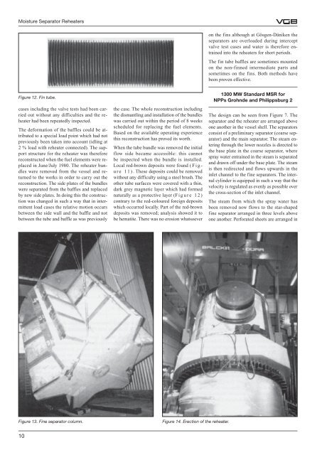
Figure 12. Fin tube.<br />
cases including the valve tests had been carried<br />
out without any difficulties and the reheater<br />
had been repeatedly inspected.<br />
The deformation of the baffles could be attributed<br />
to a special load point which had not<br />
previously been taken into account (idling at<br />
2 % load with reheater connected). The support<br />
structure for the reheater was therefore<br />
reconstructed when the fuel elements were replaced<br />
in June/July 1980. The reheater bundles<br />
were removed from the vessel and returned<br />
to the works in order to carry out the<br />
reconstruction. The side plates of the bundles<br />
were separated from the baffles and replaced<br />
by new side plates. In doing this the construction<br />
was changed in such a way that in intermittent<br />
load cases the relative motion occurs<br />
between the side wall and the baffle and not<br />
between the tube and baffle as was previously<br />
10<br />
the case. The whole reconstruction including<br />
the dismantling and installation of the bundles<br />
was carried out within the period of 8 weeks<br />
scheduled for replacing the fuel elements.<br />
Based on the available operating experience<br />
this reconstruction has proved its worth.<br />
When the tube bundle was removed the initial<br />
flow side became accessible: this cannot<br />
be inspected when the bundle is installed.<br />
Local red-brown deposits were found ( F i g -<br />
u r e 1 1 ) . These deposits could be removed<br />
without any difficulty using a steel brush. The<br />
other tube surfaces were covered with a thin,<br />
dark grey magnetic layer which had formed<br />
naturally as a protective layer (F i g u r e 1 2 )<br />
contrary to the red-coloured foreign deposits<br />
which occurred locally. Part of the red-brown<br />
deposits was removed; analysis showed it to<br />
be hematite. There was no erosion whatsoever<br />
Figure 13. Fine separator column. Figure 14. Erection of the reheater.<br />
on the fins although at Gösgen-Däniken the<br />
separators are overloaded during intercept<br />
valve test cases and water is therefore entrained<br />
into the reheaters for short periods.<br />
The fin tube baffles are sometimes mounted<br />
on the non-finned intermediate parts and<br />
sometimes on the fins. Both methods have<br />
been proven effective.<br />
1300 MW Standard MSR for<br />
NPPs Grohnde and Philippsburg 2<br />
The design can be seen from Figure 7. The<br />
separator and the reheater are arranged above<br />
one another in the vessel shell. The separators<br />
consist of a preliminary separator (coarse separator)<br />
and the main separator. The steam entering<br />
through the lower nozzles is directed to<br />
the base plate in the coarse separator, where<br />
spray water entrained in the steam is separated<br />
and drawn off under the base plate. The steam<br />
is then redirected and flows upwards in the<br />
inlet channel to the fine separators. The internal<br />
cylinder is equipped in such a way that the<br />
velocity is regulated as evenly as possible over<br />
the cross-section of the inlet channel.<br />
The steam from which the spray water has<br />
been removed now flows to the star-shaped<br />
fine separator arranged in three levels above<br />
one another. Perforated sheets are arranged in