Moisture Separator Reheater - Balcke-Dürr Energietechnik Gmbh
Moisture Separator Reheater - Balcke-Dürr Energietechnik Gmbh
Moisture Separator Reheater - Balcke-Dürr Energietechnik Gmbh

You also want an ePaper? Increase the reach of your titles
YUMPU automatically turns print PDFs into web optimized ePapers that Google loves.
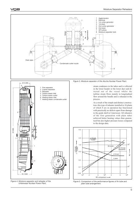
22 000<br />
7<br />
3<br />
6<br />
Ø 3 200<br />
2<br />
Ø 4 500<br />
Drain pipe<br />
Figure 4. <strong>Moisture</strong> separator and reheater of the<br />
Unterweser Nuclear Power Plant.<br />
5<br />
1<br />
4<br />
1 Fine separator<br />
2 Coarse separator<br />
3 <strong>Reheater</strong><br />
4 Turbine steam inlet<br />
5 Turbine steam outlet<br />
6 Heating steam inlet<br />
7 Heating steam condensate outlet<br />
Condensate outlet nozzle<br />
7<br />
1<br />
2<br />
3<br />
4<br />
5<br />
Agglomerator<br />
6<br />
<strong>Moisture</strong> <strong>Separator</strong> <strong>Reheater</strong>s<br />
1 Agglomerator<br />
2 Manhole<br />
3 1st vortex generator<br />
4 1st drain<br />
5 2nd vortex generator<br />
6 2nd drain<br />
7 HP turbine<br />
8 <strong>Moisture</strong> separator tank<br />
Figure 3. <strong>Moisture</strong> separator of the Atucha Nuclear Power Plant.<br />
e finned<br />
e plain<br />
j;<br />
5.0<br />
2.0<br />
1.0<br />
0.5<br />
0.2<br />
0.1<br />
steam condenses in the tubes and is collected<br />
in the lower header or the lower duct and directed<br />
out of the vessel whilst the<br />
turbine steam flows mainly in longitudinal<br />
flow around the bundle and is reheated in the<br />
process.<br />
As a result of the simple and distinct construction,<br />
this type of reheater installed in 10 plants<br />
of which 8 are in operation has functioned<br />
with practically no defects apart from damage<br />
to the guide shell in Unterweser. All reheaters<br />
of the first generation with plain tubes<br />
achieved better heating values than guaranteed<br />
but also higher pressure losses compared<br />
to the design data.<br />
e finned<br />
e plain<br />
NU plain<br />
8<br />
j finned<br />
j plain<br />
NU finned<br />
(apparent)<br />
10<br />
RE comparison<br />
4 2 5 105 2 5 106 0.05<br />
Figure 5. Comparison of the performance figures of fin tube and<br />
plain tube arrangement.<br />
10 3<br />
NU<br />
10 2<br />
5