Automatic In-betweening in Computer Assisted Animation ... - CiteSeer
Automatic In-betweening in Computer Assisted Animation ... - CiteSeer
Automatic In-betweening in Computer Assisted Animation ... - CiteSeer

You also want an ePaper? Increase the reach of your titles
YUMPU automatically turns print PDFs into web optimized ePapers that Google loves.
Copyright c○2001 <strong>In</strong>stitute of Electrical and Electronics Eng<strong>in</strong>eers, <strong>In</strong>c. All rights reserved. 1<br />
<strong>Automatic</strong> <strong>In</strong>-<strong>between<strong>in</strong>g</strong> <strong>in</strong> <strong>Computer</strong> <strong>Assisted</strong> <strong>Animation</strong> by Exploit<strong>in</strong>g 2.5D<br />
Modell<strong>in</strong>g Techniques<br />
Fabian Di Fiore, Philip Schaeken, Koen Elens, Frank Van Reeth<br />
Expertise Centre for Digital Media - Limburg University Centre<br />
Wetenschapspark 2, B-3590 Diepenbeek<br />
Belgium<br />
E-mail: {fabian.difiore, philip.schaeken, koen.elens, frank.vanreeth}@luc.ac.be<br />
Abstract<br />
This paper <strong>in</strong>troduces a new method for automatic <strong>in</strong><strong>between<strong>in</strong>g</strong><br />
<strong>in</strong> computer assisted traditional animation. The<br />
solution is based on novel 2.5D modell<strong>in</strong>g and animation<br />
techniques with<strong>in</strong> the context of a multi-level approach,<br />
start<strong>in</strong>g with basic 2D draw<strong>in</strong>g primitives (curves) at level<br />
0, over explicit 2.5D modell<strong>in</strong>g structures at level 1 and <strong>in</strong>clusion<br />
of 3D <strong>in</strong>formation by means of skeletons at level 2,<br />
to high-level deformation tools (and possibly other tools for<br />
support<strong>in</strong>g specific purposes such as facial expression) at<br />
level 3. The underly<strong>in</strong>g methodologies are expla<strong>in</strong>ed and<br />
implementation results are elucidated.<br />
Keywords: 2.5D modell<strong>in</strong>g, 2.5D animation, character<br />
animation, real-time animation, <strong>in</strong>terpolation, <strong>in</strong><strong>between<strong>in</strong>g</strong>,<br />
computer-assisted animation.<br />
1. <strong>In</strong>troduction<br />
Traditional animation is an art form. It is the process of<br />
creat<strong>in</strong>g a sequence of drawn images which, when shown<br />
one after the other at a fixed rate, resembles a lifelike movement.<br />
When we speak about 2D animation <strong>in</strong> the context<br />
of this paper, we refer to animations where the background,<br />
objects (build<strong>in</strong>gs, cars, . . . ) and characters (persons, animals,<br />
. . . ) are hand-drawn. The movements and orientations<br />
of the characters <strong>in</strong> the drawn world resemble real life<br />
(e.g. a squirrel mov<strong>in</strong>g beh<strong>in</strong>d or <strong>in</strong> front of a tree) but the<br />
characters themselves do not mimic reality exactly: animators<br />
do not want to reproduce real life but they tend to create<br />
animations that are recognizable by people. At the same<br />
time the animation can be playful, it can be a caricature or<br />
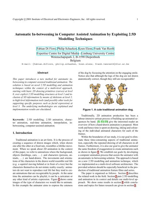
any other k<strong>in</strong>d of artistic expression. Figure 1 shows some<br />
images of the type of characters we would like to animate.<br />
<strong>In</strong> this example the animator aims to express the cuteness<br />
of the dog by focuss<strong>in</strong>g the attention on the engag<strong>in</strong>g smile.<br />
Notice also that although the legs of the dog are not drawn<br />
anatomically correct, though they still are recognizable!<br />
Figure 1. A cute traditional animation dog.<br />
Traditionally, 2D animation production has been a<br />
labour-<strong>in</strong>tensive artisan process of build<strong>in</strong>g up animated sequences<br />
by hand. [2, 13, 15] give the <strong>in</strong>terested reader an<br />
overview of how a hand-drawn animation is prepared. Most<br />
work and hence time is spent on draw<strong>in</strong>g, <strong>in</strong>k<strong>in</strong>g and colour<strong>in</strong>g<br />
of the <strong>in</strong>dividual animated characters for each of the<br />
frames.<br />
With<strong>in</strong> the boundaries of our study, it is our goal to elim<strong>in</strong>ate<br />
these time-consum<strong>in</strong>g aspects of traditional animation,<br />
especially the repeated draw<strong>in</strong>g of all characters <strong>in</strong> all<br />
frames. Furthermore, it is also our goal to give the animator<br />
the same freedom of exaggeration to create animations such<br />
as shown <strong>in</strong> figure 1. We establish our goals by develop<strong>in</strong>g<br />
a computer animation process that assists the animator with<br />
an automatic <strong>in</strong>-<strong>between<strong>in</strong>g</strong> solution. The approach is based<br />
on a new 2.5D modell<strong>in</strong>g and animation technique, which<br />
we implemented as a multi-level software architecture. The<br />
provided solution should be especially beneficial <strong>in</strong> the production<br />
of traditional animation feature films and series.<br />
The paper is organised as follows. Section 2 describes<br />
the related work <strong>in</strong> the field. Section 3 puts 2.5D modell<strong>in</strong>g<br />
and animation <strong>in</strong> its context and details our multi-level approach.<br />
We show some results <strong>in</strong> section 4 while conclusions<br />
and topics for future research are given <strong>in</strong> section 5.
Copyright c○2001 <strong>In</strong>stitute of Electrical and Electronics Eng<strong>in</strong>eers, <strong>In</strong>c. All rights reserved. 2<br />
2. Related work<br />
Already <strong>in</strong> the early seventies, [3] reported on the use of<br />
computers <strong>in</strong> the generation of keyframed animation. Catmull<br />
[5] was among the first to discuss the issues underly<strong>in</strong>g<br />
computer-assisted animation, <strong>in</strong>dicat<strong>in</strong>g that the ma<strong>in</strong> problem<br />
is to be found <strong>in</strong> the lack of explicit 3D <strong>in</strong>formation <strong>in</strong><br />
2D hand-drawn cartoon pictures, mak<strong>in</strong>g <strong>in</strong> particular the<br />
problem of <strong>in</strong>-<strong>between<strong>in</strong>g</strong> a hard task. Even for the ’simple’<br />
cases <strong>in</strong> which animation is parallel to the draw<strong>in</strong>g canvas,<br />
no straightforward solutions exist(ed). For example, calculat<strong>in</strong>g<br />
<strong>in</strong>-betweens us<strong>in</strong>g a l<strong>in</strong>ear <strong>in</strong>terpolation of Cartesian<br />
coord<strong>in</strong>ates does not preserve shapes or proportions, as<br />
shown <strong>in</strong> figure 2.<br />
Figure 2. Rotat<strong>in</strong>g arm with the shoulder as<br />
pivot po<strong>in</strong>t. Us<strong>in</strong>g l<strong>in</strong>ear <strong>in</strong>terpolation causes<br />
the hand to follow the path of the straight l<strong>in</strong>e.<br />
<strong>In</strong> that case, dur<strong>in</strong>g the animation, the arm will<br />
shr<strong>in</strong>k at the beg<strong>in</strong>n<strong>in</strong>g and enlarge towards<br />
the end of the animation. It is obvious that the<br />
hand has to follow the curved circle segment<br />
path dur<strong>in</strong>g animation <strong>in</strong> order to preserve the<br />
orig<strong>in</strong>al shape and proportions of the arm.<br />
Some of the problems with <strong>in</strong>-<strong>between<strong>in</strong>g</strong> have later<br />
been addressed by [17], utilis<strong>in</strong>g mov<strong>in</strong>g po<strong>in</strong>t constra<strong>in</strong>ts.<br />
[27] proposes the use of l<strong>in</strong>ear <strong>in</strong>terpolation of polar coord<strong>in</strong>ates<br />
to circumvent the abovementioned shr<strong>in</strong>k<strong>in</strong>g problem.<br />
[12] discusses an experimental 2.5D keyframe animation<br />
system, focuss<strong>in</strong>g on three goals: (i) to achieve an easy<br />
and <strong>in</strong>tuitive user <strong>in</strong>terface; (ii) to be able to produce character<br />
animation; and (iii) the flexible re-use of previously<br />
def<strong>in</strong>ed motion sequences. He succeeded <strong>in</strong> achiev<strong>in</strong>g his<br />
aims, but animations could suffer from occlusion problems.<br />
Litw<strong>in</strong>owicz acknowledges that this is due to the use of a<br />
strictly prioritised draw<strong>in</strong>g order <strong>in</strong> his solution, but he did<br />
not <strong>in</strong>dicate any further research to prevent this.<br />
[15] re-addresses the issues <strong>in</strong> the ’78 paper of Catmull,<br />
confirm<strong>in</strong>g automat<strong>in</strong>g <strong>in</strong>-<strong>between<strong>in</strong>g</strong> to be the key problem<br />
<strong>in</strong> 2D animation, which essentially breaks down <strong>in</strong>to two<br />
sub-problems: how silhouette outl<strong>in</strong>es change and how the<br />
various parts of the object occlude themselves. The use of<br />
(i) polar coord<strong>in</strong>ate <strong>in</strong>terpolation, (ii) appropriate cont<strong>in</strong>uity<br />
control and (iii) a 2.5D hierarchy display model (HDM)<br />
are identified as key components to effective <strong>in</strong>-<strong>between<strong>in</strong>g</strong>.<br />
The work presented <strong>in</strong> this paper focuses on detail<strong>in</strong>g some<br />
of the issues addressed <strong>in</strong> [15], by exploit<strong>in</strong>g explicit 2.5D<br />
modell<strong>in</strong>g of hierarchical models <strong>in</strong> a multi-level animation<br />
architecture.<br />
Our previously reported work on exploit<strong>in</strong>g 2.5D animation<br />
techniques focuses on position<strong>in</strong>g and animat<strong>in</strong>g hierarchical<br />
2D cut-out animation characters [22] respectively<br />
free form characters [6] <strong>in</strong> a 3D world space.<br />
Over the last few years various commercial software<br />
packages have been developed for assist<strong>in</strong>g the animator <strong>in</strong><br />
the production of traditional cartoon animation. [9] provides<br />
a good overview on the available systems, <strong>in</strong>clud<strong>in</strong>g<br />
some case studies.<br />
We conclude this section by mention<strong>in</strong>g that ’Toon render<strong>in</strong>g’,<br />
a subcategory <strong>in</strong> the non-photorealistic render<strong>in</strong>g<br />
(NPR) doma<strong>in</strong>, also offers solutions to the occlusion problem<br />
and the chang<strong>in</strong>g silhouette problem. Start<strong>in</strong>g from 3D<br />
geometrical models, NPR techniques can generate possibly<br />
stylised cartoon render<strong>in</strong>gs depict<strong>in</strong>g outl<strong>in</strong>es with the correct<br />
distortions and occlusions. However, two ma<strong>in</strong> drawbacks<br />
can be identified as far as traditional cartoon animation<br />
is concerned: (i) the approaches require extensive modell<strong>in</strong>g<br />
and animation of 3D characters and objects; and (ii)<br />
the f<strong>in</strong>al results are known to render the underly<strong>in</strong>g 3D geometry<br />
’too’ accurate! <strong>In</strong> traditional animation, animators<br />
do not mimic reality exactly; <strong>in</strong>stead they like to exaggerate<br />
it, putt<strong>in</strong>g emphasis on specific expressive details that<br />
cannot exist <strong>in</strong> the real 3D world.<br />
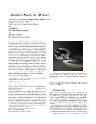
For example, consider the case of show<strong>in</strong>g the relative<br />
position of eyes on a head. Figure 3 shows images obta<strong>in</strong>ed<br />
by us<strong>in</strong>g NPR techniques of a cartoon man’s head face-on<br />
(a) and sideways (b), and the same views as an animator<br />
is likely to draw it (c, d). We see that the side view (b)<br />
is geometrically correct (only the right eye is shown), contrary<br />
to (d) where the eyes are not drawn anatomically correct.<br />
However, the eyes <strong>in</strong> (d) might be more effective at<br />
express<strong>in</strong>g the sense of action that the animator would like<br />
to emphasize.<br />
An <strong>in</strong>-depth overview of published work <strong>in</strong> the NPR doma<strong>in</strong><br />
can be found at [18].<br />
3. Modell<strong>in</strong>g and animation <strong>in</strong> 2.5D<br />
3.1. Traditional 2D animation versus 3D computer<br />
animation<br />
When look<strong>in</strong>g to the 3D computer animation pipel<strong>in</strong>e<br />
(from a broad perspective), one can generally dist<strong>in</strong>guish<br />
clearly between (i) a modell<strong>in</strong>g stage, <strong>in</strong> which the 3D objects,<br />
characters and backgrounds are <strong>in</strong>teractively modelled<br />
with 3D polygon meshes or curved surfaces, (ii) an
Copyright c○2001 <strong>In</strong>stitute of Electrical and Electronics Eng<strong>in</strong>eers, <strong>In</strong>c. All rights reserved. 3<br />
Figure 3. These pictures show (a) a man’s<br />
head face-on and (b) a side-view obta<strong>in</strong>ed by<br />
NPR techniques and the same views (c, d) as<br />
an animator is likely to draw it.<br />
animation stage, <strong>in</strong> which objects and characters are animated<br />
us<strong>in</strong>g a variety of animation tools, and (iii) a render<strong>in</strong>g<br />
stage, <strong>in</strong> which the f<strong>in</strong>al images of the animation sequence<br />
are be<strong>in</strong>g calculated frame by frame.<br />
<strong>In</strong> traditional 2D animation [2, 13, 15], the ’<strong>In</strong>k and<br />
pa<strong>in</strong>t’ process could somewhat be regarded as be<strong>in</strong>g the<br />
equivalent of the render<strong>in</strong>g stage <strong>in</strong> 3D animation, but the<br />
’modell<strong>in</strong>g’ and ’animation’ processes, however, are not explicitly<br />
present. They are comb<strong>in</strong>ed <strong>in</strong>to a s<strong>in</strong>gle draw<strong>in</strong>g<br />
process, which can be broken down <strong>in</strong>to three sub-stages:<br />
(i) ma<strong>in</strong> animators draw the most significant images, which<br />
are referred to as extreme frames or poses, conta<strong>in</strong><strong>in</strong>g the<br />
major features of the action; (ii) assistant animators produce<br />
key frames between the extreme frames, hence detail<strong>in</strong>g<br />
the desired animation action; while (iii) less experienced<br />
animators are responsible for creat<strong>in</strong>g all the rema<strong>in</strong><strong>in</strong>g <strong>in</strong>between<br />
frames of the animation.<br />
3.2. Our solution: multi-level 2.5D modell<strong>in</strong>g and<br />
animation<br />
3.2.1. <strong>In</strong>troduction. Consider<strong>in</strong>g 2D animation from a technical<br />
standpo<strong>in</strong>t, two dist<strong>in</strong>ctly different categories can be<br />
considered: (I) transformations <strong>in</strong> a plane parallel to the<br />
draw<strong>in</strong>g canvas (the x-y plane), such as rotations around<br />
the z-axis and translations with<strong>in</strong> a plane parallel to the x-y<br />
plane, and (II) transformations outside the draw<strong>in</strong>g plane,<br />
especially all rotations around an axis different from the zaxis.<br />
The former category of transformations is relatively<br />
easy to deal with, whereas the latter is the ma<strong>in</strong> cause of<br />
all the trouble <strong>in</strong> automat<strong>in</strong>g the <strong>in</strong>-<strong>between<strong>in</strong>g</strong> process (i.e.<br />
the underly<strong>in</strong>g sub-problems of silhouette changes and selfocclusion).<br />
It is <strong>in</strong> the latter type of animation where the<br />
3D structure comes <strong>in</strong>to play that is underly<strong>in</strong>g the objects<br />
and characters <strong>in</strong> traditional animation (and which is present<br />
<strong>in</strong> the animator’s - and viewer’s - m<strong>in</strong>d), but which is not<br />
present <strong>in</strong> the 2D draw<strong>in</strong>gs.<br />
The 2.5D animation systems referenced <strong>in</strong> section 2,<br />
such as [6], [12] and [22] are capable of animat<strong>in</strong>g characters<br />
and objects <strong>in</strong> category (I): they essentially narrow<br />
down to animat<strong>in</strong>g hierarchies of layered 2D sub-shapes<br />
with<strong>in</strong> an overall layered 2D world space or a true 3D world<br />
space; all transformations take place <strong>in</strong> planes parallel to the<br />
draw<strong>in</strong>g plane and the draw<strong>in</strong>g order of the 2D sub-shapes<br />
is essentially fixed <strong>in</strong> time.<br />
A true 2.5D animation system should also be capable of<br />
animat<strong>in</strong>g characters <strong>in</strong> category (II). Hence, we present a<br />
multi-level 2.5D modell<strong>in</strong>g and animation approach:<br />
• level 0 holds the basic build<strong>in</strong>g primitives, be<strong>in</strong>g sets<br />
of attributed 2D curves (cf. section 3.3),<br />
• level 1 manages and processes explicit 2.5D modell<strong>in</strong>g<br />
<strong>in</strong>formation,<br />
• level 2 <strong>in</strong>corporates 3D <strong>in</strong>formation by means of 3D<br />
skeletons, and<br />
• level 3 is more open-ended and <strong>in</strong>troduces higher level<br />
tools such as non-aff<strong>in</strong>e deformations, facial expressions,<br />
etc.<br />
As will be clear from the subsequent subsections, our<br />
2.5D methodology clearly dist<strong>in</strong>guishes a modell<strong>in</strong>g phase<br />
and an animation phase (hence follow<strong>in</strong>g 3D computer animation<br />
<strong>in</strong> this respect).<br />
3.2.2. Level 1: explicit 2.5D modell<strong>in</strong>g <strong>in</strong>formation. Level<br />
1 is fundamental <strong>in</strong> the realisation of category (II) functionality.<br />
The basic notion can best be understood by observ<strong>in</strong>g<br />
the fact that especially rotation of (sub-objects) around the<br />
x- and y-axis needs special attention. Referr<strong>in</strong>g back to the<br />
character depicted <strong>in</strong> figure 3(c), one can easily see that rotation<br />
around the z-axis would not cause any problems: the<br />
outl<strong>in</strong>es and silhouettes of the character’s head as well as<br />
the draw<strong>in</strong>g order of the various sub-objects would rema<strong>in</strong><br />
fixed with respect to each other. When rotat<strong>in</strong>g the character<br />
around the vertical (y-)axis, however, one can clearly notice<br />
(figure 3(d)) heavy changes <strong>in</strong> outl<strong>in</strong>es and silhouettes as<br />
well as changes <strong>in</strong> draw<strong>in</strong>g order (and when rotat<strong>in</strong>g further<br />
than <strong>in</strong>dicated <strong>in</strong> figure 3(d), even more draw<strong>in</strong>g order<br />
changes would be needed, as all the facial parts would disappear<br />
beh<strong>in</strong>d the head itself).<br />
Hence, we propose a 2.5D modell<strong>in</strong>g structure <strong>in</strong> which<br />
characters and objects are modelled as sets of depth ordered<br />
primitives (open or closed curves, cf. section 3.3) with respect<br />
to the x-axis and y-axis rotations. For each set of ’important’<br />
x-y-rotations of the object/character relative to the<br />
virtual camera, the animator draws a set of ordered curve<br />
primitives, functionally comparable to the extreme frames
Copyright c○2001 <strong>In</strong>stitute of Electrical and Electronics Eng<strong>in</strong>eers, <strong>In</strong>c. All rights reserved. 4<br />
<strong>in</strong> traditional animation (cf. section 3.1), and which we<br />
therefore also call an ’extreme frame’. <strong>In</strong>ternally, for each<br />
2.5D animation object/character, the support<strong>in</strong>g data structure<br />
is a straightforward list, <strong>in</strong>dexed by two rotation angles.<br />
For each extreme frame, it holds all the references<br />
to the underly<strong>in</strong>g curve primitives (each of which can have<br />
a mean<strong>in</strong>gful name) as well as the draw<strong>in</strong>g order of these<br />
primitives <strong>in</strong> this extreme frame.<br />
Figure 4 shows the UI components support<strong>in</strong>g level 1<br />
functionality. The render<strong>in</strong>g w<strong>in</strong>dow shows a graphical render<strong>in</strong>g<br />
of the depth-ordered curves (<strong>in</strong>clud<strong>in</strong>g all the control<br />
po<strong>in</strong>ts of the underly<strong>in</strong>g curves - which can be switched of<br />
by hitt<strong>in</strong>g a toggle <strong>in</strong> the ’Properties’ w<strong>in</strong>dow). For each extreme<br />
frame, the ’Sort<strong>in</strong>g Order’ w<strong>in</strong>dow depicts the draw<strong>in</strong>g<br />
order of the sub-objects at issue. New extreme frames<br />
are entered by select<strong>in</strong>g new rotational angles (us<strong>in</strong>g the Xaxis<br />
and Y-axis slider bars), draw<strong>in</strong>g the respective curves<br />
of the sub-objects and sett<strong>in</strong>g their relative draw<strong>in</strong>g order.<br />
<strong>In</strong> order to simplify the correspondence problem when <strong>in</strong>terpolat<strong>in</strong>g<br />
between various <strong>in</strong>stances of a particular curve,<br />
the curve draw<strong>in</strong>g is currently implemented as a ’curve copy<br />
and re-edit’-tool.<br />
Figure 4. A snapshot of some UI components<br />
support<strong>in</strong>g level 1 functionality.<br />
Figure 5 shows four example extreme frames, which<br />
are created for a 2.5D house object. The number of extreme<br />
frames to be produced for a given 2.5D animation<br />
object/character obviously depends upon its complexity and<br />
the range of angles it traverses with respect to the animation<br />
camera. <strong>In</strong> this example case, the four extreme frames suffice<br />
to automatically generate each frame of an animation<br />
<strong>in</strong> which the virtual camera makes a vertical angle (relative<br />
to the house) between 0 and 30 degrees, and a relative horizontal<br />
angle between 0 and 45 degrees.<br />
Figure 5. These are the four extreme frames<br />
created by the animator. <strong>In</strong> each case the<br />
same house is drawn but as if the virtual camera<br />
is rotated some degrees around the vertical<br />
(Y) or horizontal (X) axis. (a) Y=0, X=0; (b)<br />
Y=0, X=45; (c) Y=30, X=0; (d) Y=30, X=45.<br />
For a representative background object or nondeformable<br />
animation object, about eight extreme frames<br />
are typically drawn to fully cover all rotational angles<br />
around the y-axis, with some additional extreme frames for<br />
rotational angles around the x-axis. This seems potentially<br />
to be a large number of extreme frames, but one should<br />
bear <strong>in</strong> m<strong>in</strong>d that the traditional (hand draw<strong>in</strong>g) animator<br />
not only has to deal with (=draw) these extreme frames, but<br />
also the key frames and the <strong>in</strong>-between frames, with little<br />
options to re-use material. <strong>In</strong> our automated approach the<br />
manual ’draw<strong>in</strong>g’ stays limited to modell<strong>in</strong>g of the extreme<br />
frames.<br />
3.2.3. Level 1: 2.5D animation. Once the extreme frames<br />
are generated, it becomes possible to automatically render<br />
snapshots of the 2.5D objects with<strong>in</strong> the range covered by<br />
the extreme frames. <strong>In</strong> order to create animated sequences,<br />
the animator specifies key frames <strong>in</strong> time, e.g., for posi-
Copyright c○2001 <strong>In</strong>stitute of Electrical and Electronics Eng<strong>in</strong>eers, <strong>In</strong>c. All rights reserved. 5<br />
tion<strong>in</strong>g and orient<strong>in</strong>g a 2.5D object or for position<strong>in</strong>g and<br />
orient<strong>in</strong>g the virtual camera <strong>in</strong> the (3D) animation world.<br />
Thus, key fram<strong>in</strong>g determ<strong>in</strong>es the tim<strong>in</strong>g of the animation<br />
sequence.<br />
Render<strong>in</strong>g such a key frame - and <strong>in</strong>deed also an <strong>in</strong>between<br />
frame - narrows down technically to utiliz<strong>in</strong>g the<br />
position and orientation of a 2.5D object to calculate the relative<br />
rotational angles (vertical and horizontal) with respect<br />
to the virtual camera. These angles are then used to search<br />
the surround<strong>in</strong>g extreme frames with respect to the horizontal<br />
and vertical angle. This can yield (i) two extreme<br />
frames, <strong>in</strong> case only extreme frames with relative orientations<br />
around a s<strong>in</strong>gle axis (mostly the vertical) are present,<br />
(ii) four extreme frames <strong>in</strong> case multiple extreme frames<br />
with relative orientations around both axes are available, or<br />
(iii) three extreme frames <strong>in</strong> case extreme frames with relative<br />
orientations around a s<strong>in</strong>gle axis (mostly the vertical)<br />
are specified aside a s<strong>in</strong>gle additional extreme frame around<br />
the other axis. The control po<strong>in</strong>ts of the draw<strong>in</strong>g primitives<br />
(curves) <strong>in</strong> level 0, referenced by the selected extreme<br />
frames, are <strong>in</strong>terpolated l<strong>in</strong>early but can also be <strong>in</strong>terpolated<br />
us<strong>in</strong>g higher order <strong>in</strong>terpolation schemes such as proposed<br />
<strong>in</strong> [11].<br />
The draw<strong>in</strong>g order specified/stored <strong>in</strong> the selected extreme<br />
frames is utilized to determ<strong>in</strong>e the draw<strong>in</strong>g order of<br />
the <strong>in</strong>terpolated curves at issue.<br />
The general problem of <strong>in</strong>terpolat<strong>in</strong>g between two 2D<br />
shapes is not trivial and has been (and still is) studied <strong>in</strong><br />
the morph<strong>in</strong>g community [26]. The correspondence problem<br />
is very important <strong>in</strong> object-space morph<strong>in</strong>g and some<br />
useful approaches may be found there. [20] <strong>in</strong>terpolate the<br />
length of the edges of the polygon and the angles between<br />
them, while [1] use Delauney triangulated polygons, and <strong>in</strong>stead<br />
of the outl<strong>in</strong>e, transform the triangles of the result<strong>in</strong>g<br />
mesh. Some researchers [4] propose an algorithm to automatically<br />
establish the correspondence. Others [10, 21] on<br />
the contrary claim that the user can best specify the correspondence<br />
manually. We follow their advice and let the user<br />
specify the correspondence as the curve draw<strong>in</strong>g is currently<br />
implemented as a ’curve copy and re-edit’-tool.<br />
Figure 6 shows some key frames of an animation sequence<br />
automatically generated us<strong>in</strong>g the four extreme<br />
frames <strong>in</strong> figure 5 and the position of the virtual camera as<br />
specified <strong>in</strong> time be the animator. The key frames specify<br />
the tim<strong>in</strong>g of a virtual camera movement (with view po<strong>in</strong>t<br />
<strong>in</strong> the center of the house) from sideways <strong>in</strong> front, upwards<br />
to up-front and then down aga<strong>in</strong> to end <strong>in</strong> front of the house.<br />
3.2.4. Level 2: 3D <strong>in</strong>formation by means of 3D skeletons.<br />
For animat<strong>in</strong>g scenery/décor elements (such as houses) and<br />
non-deformable animated objects only undergo<strong>in</strong>g aff<strong>in</strong>e<br />
transformations (such as cars or airplanes), level 1 function-<br />
Figure 6. Key frames of an animation sequence<br />
us<strong>in</strong>g the extreme frames <strong>in</strong> figure 5.<br />
ality could suffice. However, for animat<strong>in</strong>g lively characters<br />
consist<strong>in</strong>g of many sub-parts and protrud<strong>in</strong>g limbs, additional<br />
support - ’more 3D’ - is needed. <strong>In</strong> our solution this<br />
corresponds to level 2 functionality.<br />
On this level, the notion of 3D skeletons, often encountered<br />
<strong>in</strong> 3D computer animation, is <strong>in</strong>troduced. A skeleton<br />
is a hierarchical structure consist<strong>in</strong>g of connected bones.<br />
Each sub-object of a given 2.5D animation character (modelled<br />
as curves <strong>in</strong>troduced at level 0) that is capable of be<strong>in</strong>g<br />
animated with respect to the other sub-objects of the character<br />
at issue, is attributed to a specific bone <strong>in</strong> the skeleton<br />
(we have an experimental set-up <strong>in</strong> which the attribution<br />
can be weighted across two connected bones, but this<br />
is not relevant to the ma<strong>in</strong> l<strong>in</strong>e of the story here). Technically,<br />
this implies that the control po<strong>in</strong>ts of the underly<strong>in</strong>g<br />
curves are def<strong>in</strong>ed <strong>in</strong> a local coord<strong>in</strong>ate system, which is<br />
placed on the bone. By manipulat<strong>in</strong>g the bones of the skeleton,<br />
the attached curves of the correspond<strong>in</strong>g sub-object will<br />
be affected. The basic categorisation <strong>in</strong>troduced <strong>in</strong> section<br />
3.2.1 is still valid <strong>in</strong> level 2: category (I) transformations are<br />
relatively easy, whereas category (II) transformations cause<br />
problems.<br />
<strong>In</strong>deed, rotation of a bone <strong>in</strong> a plane parallel to the draw<strong>in</strong>g<br />
canvas (i.e. around the z-axis) implies a similar rotation<br />
of the attributed control po<strong>in</strong>ts - and hence curves - of the<br />
sub-object at issue. Category (II) transformations are handled<br />
broadly analogous to the level 1 solution, by exploit<strong>in</strong>g<br />
a 2.5D modell<strong>in</strong>g structure <strong>in</strong> which extreme frames are<br />
def<strong>in</strong>ed. Two differences exist as compared to the level 1<br />
approach: firstly, the modell<strong>in</strong>g of curves at extreme frames<br />
does no longer need the two slider bars for sett<strong>in</strong>g the x-axis<br />
and y-axis angles, as these are now handled implicitly by<br />
orient<strong>in</strong>g the bones <strong>in</strong> 3D space; and secondly, the explicit<br />
manual order<strong>in</strong>g of sub-objects is also no longer needed, as<br />
this order<strong>in</strong>g is done automatically us<strong>in</strong>g the 3D positional
Copyright c○2001 <strong>In</strong>stitute of Electrical and Electronics Eng<strong>in</strong>eers, <strong>In</strong>c. All rights reserved. 6<br />
<strong>in</strong>formation of the bones to which the curves are attributed.<br />
<strong>In</strong> case the automatic order<strong>in</strong>g should not produce the desired<br />
result, e.g. due to co<strong>in</strong>cid<strong>in</strong>g or cross<strong>in</strong>g (when the<br />
right hand moves beh<strong>in</strong>d the hip <strong>in</strong> figure 7) bones or when<br />
the animator wants some dramatic effect not adher<strong>in</strong>g the<br />
bone-order, some additional book-keep<strong>in</strong>g <strong>in</strong> the 2.5D data<br />
structure is used to fall back to the normal level 1 approach.<br />
Figure 7 shows a typical skeleton support<strong>in</strong>g composition<br />
and manipulation of a 2.5D animation character.<br />
Figure 7. (a) shows a typical 3D skeleton support<strong>in</strong>g<br />
the composition and manipulation of<br />
a 2.5D animation character, whereas (b) depicts<br />
the same animation character <strong>in</strong> ’filled’<br />
mode us<strong>in</strong>g a sort<strong>in</strong>g order derived automatically<br />
from the 3D skeleton bones.<br />
The approach underly<strong>in</strong>g the 2.5D animation creation <strong>in</strong><br />
level 2 is also similar to the solution provided on level 1,<br />
and narrows down to<br />
• modell<strong>in</strong>g of the 3D skeleton and attribut<strong>in</strong>g subobjects<br />
of the 2.5D animation character to a specific<br />
bone;<br />
• specification of key frames by the animator, now by<br />
orient<strong>in</strong>g skeleton bones <strong>in</strong> time;<br />
• render<strong>in</strong>g of the key frames (and <strong>in</strong>-between frames),<br />
which aga<strong>in</strong> calculates relative rotational angles with<br />
respect to the virtual camera <strong>in</strong> order to f<strong>in</strong>d the appropriate<br />
extreme frames; and<br />
• <strong>in</strong>terpolat<strong>in</strong>g the curves at issue, now draw<strong>in</strong>g them <strong>in</strong><br />
an order directly derived from the 3D positional data<br />
of the bones.<br />
Obviously, key frames could also be specified by exploit<strong>in</strong>g<br />
<strong>in</strong>verse k<strong>in</strong>ematics [7, 25] or other physics based approaches.<br />
3.2.5. Level 3: high-level tools. Level 3 offers the opportunity<br />
to <strong>in</strong>clude <strong>in</strong> the proposed solution high-level tools<br />
on top of the level 2 (and also levels 1 and 0) functionality.<br />
Examples of these tools are high-level deformation<br />
tools and tools for specific purposes, such as facial animation.<br />
Here, we present a category (I) manipulation tool that<br />
works on control po<strong>in</strong>ts across various sub-objects. Before<br />
manipulat<strong>in</strong>g the curves at issue, a group of control po<strong>in</strong>ts<br />
is selected by draw<strong>in</strong>g a selection lasso or rectangle over<br />
the part of the character one wants to change, similar as one<br />
would use <strong>in</strong> a bitmap editor (cf. figure 8).<br />
Figure 8. Group of control po<strong>in</strong>ts.<br />
The control po<strong>in</strong>ts with<strong>in</strong> the selection will be marked as<br />
a group. The control po<strong>in</strong>ts <strong>in</strong> figure 8 are shown to visualize<br />
the group for illustrative purposes. Like <strong>in</strong> bitmap editors,<br />
a tool for transform<strong>in</strong>g a selection of the draw<strong>in</strong>g can<br />
be def<strong>in</strong>ed. The transformation tool encapsulates a pivot<br />
po<strong>in</strong>t, a translate tool, a scale tool and a rotate tool. The<br />
advantage of transform<strong>in</strong>g a group that consists of control<br />
po<strong>in</strong>ts <strong>in</strong>stead of a selection of pixels is that the curves will<br />
stay connected (cf. figure 9).<br />
Figure 9. High-level deformation tool.<br />
When us<strong>in</strong>g the pivot po<strong>in</strong>t as an anchor for the group<br />
we can <strong>in</strong>terconnect several groups. This allows the user to<br />
create a hierarchical model of a curve draw<strong>in</strong>g based on the<br />
natural anatomy of the character. Such a model can be used<br />
to control the movement of a cartoon character <strong>in</strong> a more<br />
suitable way with the aid of forward and <strong>in</strong>verse k<strong>in</strong>ematics<br />
tools (this implies the direct use of the underly<strong>in</strong>g 3D<br />
skeleton def<strong>in</strong>ed <strong>in</strong> level 2).<br />
3.3. Curve/outl<strong>in</strong>e representation<br />
For research purposes outside the context of this paper,<br />
we decided to utilize subdivision curves to represent subobjects<br />
at level 0 <strong>in</strong> our solution. We refer the reader to [28]<br />
for an <strong>in</strong>-depth overview of the state of the art <strong>in</strong> subdivision
Copyright c○2001 <strong>In</strong>stitute of Electrical and Electronics Eng<strong>in</strong>eers, <strong>In</strong>c. All rights reserved. 7<br />
technology. <strong>In</strong> our case we opted for subdivision curves<br />
with an additional support of normal <strong>in</strong>terpolation and local<br />
tension control around control po<strong>in</strong>ts [23]. This allows us to<br />
use only a limited number of control po<strong>in</strong>ts to fully control<br />
a subject with an irregular outl<strong>in</strong>e (cf. figure 10). Other<br />
curve types such as Bézier curves or NURBS [14] could<br />
have been used just as well.<br />
Figure 10. (a) shows a open subdivision curve<br />
that has two <strong>in</strong>terpolat<strong>in</strong>g control po<strong>in</strong>ts while<br />
(b) shows the ability of tension control. These<br />
k<strong>in</strong>ds of curves are used to model the character<br />
of figure (c).<br />
Each curve can be closed or opened and can be coloured<br />
(outl<strong>in</strong>es as well as <strong>in</strong>ternally). Also, the curves can have a<br />
vary<strong>in</strong>g l<strong>in</strong>e thickness.<br />
4. Results<br />
<strong>In</strong> this section we show some results of our proposed<br />
solution.<br />
Figure 11 shows some snapshots of animation exploit<strong>in</strong>g<br />
the data presented <strong>in</strong> figures 5 and 6, act<strong>in</strong>g as a representative<br />
of 2.5D animation of a typical background/décor<br />
element for which level 1 functionality suffices.<br />
Figure 13 shows some animation snapshots of an airplane,<br />
act<strong>in</strong>g as a representative of 2.5D animation of nondeformable<br />
animated objects only undergo<strong>in</strong>g aff<strong>in</strong>e transformations.<br />
Notice that the objects can be fairly irregular<br />
and may even conta<strong>in</strong> holes. Also for this type of object,<br />
level 1 functionality suffices. We used the extreme frames<br />
shown <strong>in</strong> figure 12 for generat<strong>in</strong>g the sequence.<br />
Figure 14 consists of three images depict<strong>in</strong>g some extreme<br />
frames of an animated hand, modelled as a skeleton<br />
based sub-object <strong>in</strong> level 2. Snapshots of an animation sequence<br />
exploit<strong>in</strong>g these extreme frames are shown <strong>in</strong> figure<br />
15.<br />
Figure 11. Snapshots of an animation of a typical<br />
background/décor element.<br />
Figure 12. These pictures show the extreme<br />
frames of a 2.5D airplane.<br />
The current implementation is written <strong>in</strong> C++ (MFC)<br />
with the use of OpenGL [8]. It offers real-time display<strong>in</strong>g<br />
and edit<strong>in</strong>g of the results, maximiz<strong>in</strong>g the comfort of the<br />
animator who wishes to adapt the animation to his artistic<br />
needs.<br />
We f<strong>in</strong>ish this section by stat<strong>in</strong>g that an animator can<br />
change at any time dur<strong>in</strong>g a production the order<strong>in</strong>g and<br />
the shape of the underly<strong>in</strong>g curves, which will implicitly<br />
generate a new extreme frame for the 2.5D animation object/character.<br />
5. Conclusions and future work<br />
<strong>In</strong> this paper, we presented a novel approach to elim<strong>in</strong>ate<br />
the time-consum<strong>in</strong>g aspects of traditional animation, especially<br />
the <strong>in</strong>dividual draw<strong>in</strong>g of all the characters <strong>in</strong> all separate<br />
frames, and at the same time reta<strong>in</strong><strong>in</strong>g the freedom of an<br />
animator to express his artistic needs. We accomplished this<br />
by mov<strong>in</strong>g towards a computer-assisted animation process,<br />
<strong>in</strong> which automatic <strong>in</strong>-<strong>between<strong>in</strong>g</strong> is realised by means of<br />
a multi-level 2.5D modell<strong>in</strong>g and animation solution. The
Copyright c○2001 <strong>In</strong>stitute of Electrical and Electronics Eng<strong>in</strong>eers, <strong>In</strong>c. All rights reserved. 8<br />
Figure 13. Snapshots of an animation of a typical<br />
animation object undergo<strong>in</strong>g only aff<strong>in</strong>e<br />
transformations.<br />
Figure 14. Extreme frames <strong>in</strong> a skeletonbased<br />
hand animation: (a) shows the hand<br />
at the start of the rotation while (b) depicts<br />
the end of it. (c) shows the same hand as<br />
after the rotation but of which all f<strong>in</strong>gers are<br />
bend down somewhat.<br />
underly<strong>in</strong>g concepts and pr<strong>in</strong>ciples have been detailed and<br />
illustrative 2.5D animation examples have been given.<br />
<strong>In</strong> future research, we want to <strong>in</strong>troduce new techniques<br />
and tools for draw<strong>in</strong>g and manipulat<strong>in</strong>g stylised curves. It<br />
is our goal to simplify the current way of modell<strong>in</strong>g the<br />
basic build<strong>in</strong>g primitives (curves) of a character at level 0<br />
of our solution. That is, we want to prevent the animator<br />
from explicit controll<strong>in</strong>g the curves. Hence, we plan to <strong>in</strong>tegrate<br />
the approach proposed by our colleagues [24], which<br />
is based on real-time process<strong>in</strong>g of (possibly pressure sensitive)<br />
stylus data for generat<strong>in</strong>g the underly<strong>in</strong>g curves on<br />
the fly. Their solution implies that graphics artists no longer<br />
need to manipulate (i.e. po<strong>in</strong>t, click and drag) control po<strong>in</strong>ts<br />
of underly<strong>in</strong>g spl<strong>in</strong>es, but rather exploit direct manipulation<br />
tools on the curves themselves. This simplifies the <strong>in</strong>teraction<br />
drastically. (As a downside on such functionality, more<br />
Figure 15. These pictures show some snapshots<br />
of an animation sequence generated<br />
from the extreme frames <strong>in</strong> figure 14.<br />
advanced methods for solv<strong>in</strong>g the correspondence problem<br />
(cf. section 3.2.3) will then have to be implemented as<br />
well.)<br />
An <strong>in</strong>terest<strong>in</strong>g level 2 extension would be to <strong>in</strong>corporate<br />
approximate (=heavily simplified) 3D models aside the 3D<br />
skeletons to support 2.5D model construction at level 0 and<br />
1. This should aid animators <strong>in</strong> keep<strong>in</strong>g the ’volume’ of<br />
their 2D characters when animat<strong>in</strong>g them.<br />
We are also <strong>in</strong>terested <strong>in</strong> do<strong>in</strong>g further research on level<br />
3 of our proposed solution; especially the <strong>in</strong>clusion of highlevel<br />
tools for modell<strong>in</strong>g and animation of facial expressions<br />
deserves additional attention. One possible way is<br />
to <strong>in</strong>tegrate <strong>in</strong>to our system the techniques alike the ones<br />
reported upon <strong>in</strong> [16] and [19].
Copyright c○2001 <strong>In</strong>stitute of Electrical and Electronics Eng<strong>in</strong>eers, <strong>In</strong>c. All rights reserved. 9<br />
Acknowledgements<br />
We gratefully express our gratitude to the European Fund<br />
for Regional Development and the Flemish Government,<br />
which are k<strong>in</strong>dly fund<strong>in</strong>g part of the research reported <strong>in</strong><br />
this paper.<br />
Part of the work is funded by the European research<br />
project IST-1999-56412 ’3DINCTRAP’. <strong>In</strong> this context, we<br />
would like to express our thanks to the various people <strong>in</strong> the<br />
project provid<strong>in</strong>g ideas and for help<strong>in</strong>g with the implementation.<br />
Our appreciations also go out to Joan Cabot and ’Xemi’<br />
Morales for their artistic contribution and to Koen Beets for<br />
implement<strong>in</strong>g earlier versions of the lower level curve techniques.<br />
Furthermore we would like to acknowledge ANDROME<br />
NV for freely putt<strong>in</strong>g available to us their CreaToon plug<strong>in</strong><br />
SDK.<br />
References<br />
[1] M. Alexa, D. Cohen-Or, and D. Lev<strong>in</strong>. As-rigid-as-possible<br />
shape <strong>in</strong>terpolation. ACM <strong>Computer</strong> Graphics (Proceed<strong>in</strong>gs<br />
of SIGGRAPH 2000), pages 157–164, 2000.<br />
[2] P. Blair. Cartoon <strong>Animation</strong>. Walter Foster Publish<strong>in</strong>g <strong>In</strong>c.,<br />
ISBN: 1-56010-084-2, 1994.<br />
[3] N. Burtnyk and M. We<strong>in</strong>. <strong>Computer</strong>-generated key-frame<br />
animation. Journal of the Society Motion Picture and Television<br />
Eng<strong>in</strong>eers, 8(3):149–153, 1971.<br />
[4] E. Carmel and D. Cohen-Or. Warp-guided object space morph<strong>in</strong>g.<br />
The Visual <strong>Computer</strong>, 13:465–478, 1997.<br />
[5] E. Catmull. The problems of computer-assisted animation.<br />
<strong>Computer</strong> Graphics, SIGGRAPH 1978, 12(3):348–353, August<br />
1978.<br />
[6] K. Con<strong>in</strong>x, F. Van Reeth, and E. Flerackers. <strong>In</strong>teractive specification<br />
of 2 1<br />
D animation by exploit<strong>in</strong>g a real-time 3D ren-<br />
2<br />
der<strong>in</strong>g architecture. Proceed<strong>in</strong>gs of Eurographics UK, London,<br />
pages 11–18, March 1996.<br />
[7] F. Di Fiore. Physics based modell<strong>in</strong>g of 3D movement<br />
<strong>in</strong> immersive virtual reality environments. Master’s thesis,<br />
Catholic University Leuven, 1997.<br />
[8] R. Fosner. OpenGL Programm<strong>in</strong>g for W<strong>in</strong>dows 95 and<br />
W<strong>in</strong>dows NT. Addison-Wesley Developers Press, ISBN: 0-<br />
20140-709-4, 1996.<br />
[9] H. Griff<strong>in</strong>. The Animator’s Guide to 2D <strong>Computer</strong> <strong>Animation</strong>.<br />
Focal Press, ISBN: 0-240-51579-X, 2001.<br />
[10] H. Johan, Y. Koiso, and T. Nishita. Morph<strong>in</strong>g us<strong>in</strong>g curves<br />
and shape <strong>in</strong>terpolation techniques. Proceed<strong>in</strong>gs of Pacific<br />
Graphics 2000, 8th Pacific Conference on <strong>Computer</strong> Graphics<br />
and Applications, pages 348–358, 2000.<br />
[11] D. Kochanek and R. Bartels. <strong>In</strong>terpolat<strong>in</strong>g spl<strong>in</strong>es with local<br />
tension, cont<strong>in</strong>uity and bias control. <strong>Computer</strong> Graphics,<br />
18(3):33–41, July 1984.<br />
[12] P. C. Litw<strong>in</strong>owicz. INKWELL: A 2.5D animation system.<br />
<strong>Computer</strong> Graphics, 25(4):113–122, 1991.<br />
[13] T. Nettleship and P. Willis. The animach<strong>in</strong>e renderer. <strong>Computer</strong><br />
Graphics, pages 90–97, 1995.<br />
[14] R. J. Oddy and P. J. Willis. Render<strong>in</strong>g NURB regions for<br />
2D animation. <strong>Computer</strong> Graphics Forum, special issue EG,<br />
11(3):C35–C44, 1992.<br />
[15] J. W. Patterson and P. J. Willis. <strong>Computer</strong> assisted animation:<br />
2D or not 2D? The <strong>Computer</strong> Journal, 37(10):829–<br />
839, 1994.<br />
[16] J. W. Paul ten Hagen. A facial repertoire for animation. Eurographics,<br />
pages 79–84, 2000.<br />
[17] W. Reeves. <strong>In</strong><strong>between<strong>in</strong>g</strong> for computer animation utiliz<strong>in</strong>g<br />
mov<strong>in</strong>g po<strong>in</strong>t constra<strong>in</strong>ts. <strong>Computer</strong> Graphics, 15(3):263–<br />
269, 1981.<br />
[18] C. Reynolds. Stylized depiction <strong>in</strong> computer graphics.<br />
World Wide Web, http://www.red3d.com/cwr/<br />
npr/.<br />
[19] Z. Ruttkay and H. Noot. Animated chartoon faces. NPAR<br />
2000: Symposium on Non-Photorealistic <strong>Animation</strong> and<br />
Render<strong>in</strong>g, pages 91–100, June 2000.<br />
[20] T. W. Sederberg and E. Greenwood. A physically based approach<br />
to 2D shape blend<strong>in</strong>g. <strong>Computer</strong> Graphics, 26:25–<br />
34, 1993.<br />
[21] M. Shapira and A. Rappoport. Shape blend<strong>in</strong>g us<strong>in</strong>g a starskeleton<br />
representation. IEEE <strong>Computer</strong> Graphics and Ap-<br />
plications, 15:44–51, 1995.<br />
[22] F. Van Reeth. <strong>In</strong>tegrat<strong>in</strong>g 2 1<br />
2<br />
D computer animation tech-<br />
niques for support<strong>in</strong>g traditional animation. Proceed<strong>in</strong>gs<br />
<strong>Computer</strong> <strong>Animation</strong>, pages 118–125, 1996.<br />
[23] F. Van Reeth and J. Claes. <strong>In</strong>terpolatory uniform subdivision<br />
curves with normal <strong>in</strong>terpolation and tension control, generat<strong>in</strong>g<br />
B-spl<strong>in</strong>es of any degree. Submitted to “The Visual<br />
<strong>Computer</strong>”, 2001.<br />
[24] G. Vansichem, E. Wauters, and F. Van Reeth. Real-time<br />
modelled draw<strong>in</strong>g and manipulation of stylised characters<br />
<strong>in</strong> a cartoon animation context. Proceed<strong>in</strong>gs of the IASTED<br />
<strong>In</strong>ternational Conference, <strong>Computer</strong> Graphics and Imag<strong>in</strong>g<br />
(CGIM 2001), pages 44–49, August 2001.<br />
[25] C. Welman. <strong>In</strong>verse k<strong>in</strong>ematics and geometric constra<strong>in</strong>ts<br />
for articulated figure manipulation. Master’s thesis, Simon<br />
Fraser University, 1993.<br />
[26] G. Wolberg. Image morph<strong>in</strong>g survey. The Visual <strong>Computer</strong>,<br />
14(8/9):360–372, 1998.<br />
[27] J. Yu. <strong>In</strong><strong>between<strong>in</strong>g</strong> for computer animation us<strong>in</strong>g polar<br />
coord<strong>in</strong>ates l<strong>in</strong>ear <strong>in</strong>terpolation. Research Report 90/R23,<br />
Department of <strong>Computer</strong> Science, University of Glasgow,<br />
September 1990.<br />
[28] D. Zor<strong>in</strong>, P. Schröder, A. Lev<strong>in</strong>, L. Kobbelt, W. Sweldens,<br />
and T. DeRose. Subdivison for modell<strong>in</strong>g and animation.<br />
SIGGRAPH 2000 Course notes 23, July 2000.