Software engineering for real-time systems
Software engineering for real-time systems
Software engineering for real-time systems

You also want an ePaper? Increase the reach of your titles
YUMPU automatically turns print PDFs into web optimized ePapers that Google loves.
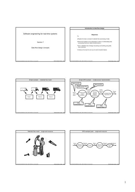
<strong>Software</strong> <strong>engineering</strong> <strong>for</strong> <strong>real</strong>-<strong>time</strong> <strong>systems</strong><br />
SOFTWARE ENGINEERING <strong>for</strong> REAL-TIME SYSTEMS (© J.E.Cooling 2003)<br />
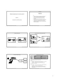
Section 7<br />
Data flow design concepts<br />
Simple example - materials flow model<br />
Robot 1 Robot 2 Robot 3<br />
Data flow design concepts - slide 1<br />
SOFTWARE ENGINEERING <strong>for</strong> REAL-TIME SYSTEMS (© J.E.Cooling 2003) Data flow design concepts - slide 3<br />
Materials flow model - single work resource<br />
SOFTWARE ENGINEERING <strong>for</strong> REAL-TIME SYSTEMS (© J.E.Cooling 2003) Data flow design concepts - slide 5<br />
To:<br />
Introduction to data flow design<br />
Objectives<br />
Explain the basic concept of materials flow processing of data.<br />
Show how <strong>systems</strong> can be described in terms of collaborating data<br />
processing machines (‘data trans<strong>for</strong>mations’).<br />
Give a detailed view of design structuring and levelling using data<br />
flow constructs.<br />
Introduce the need <strong>for</strong> and use of control trans<strong>for</strong>mations<br />
SOFTWARE ENGINEERING <strong>for</strong> REAL-TIME SYSTEMS (© J.E.Cooling 2003) Data flow design concepts - slide 2<br />
Data in to DT1<br />
Sonar<br />
echo<br />
return<br />
Simple DFD example - multiprocessor implementation<br />
Data out from DT1<br />
Process sonar<br />
signal<br />
(Processor 1)<br />
Processed<br />
sonar<br />
signal<br />
Data in to DT2<br />
Per<strong>for</strong>m<br />
spectral<br />
analysis<br />
(Processor 2)<br />
Sonar<br />
spectral<br />
data<br />
Data<br />
trans<strong>for</strong>mation 1 Data<br />
trans<strong>for</strong>mation 2 Data<br />
trans<strong>for</strong>mation 3<br />
Evaluate threat<br />
(processor 3)<br />
Threat<br />
data<br />
SOFTWARE ENGINEERING <strong>for</strong> REAL-TIME SYSTEMS (© J.E.Cooling 2003) Data flow design concepts - slide 4<br />
Uncut<br />
bar<br />
Measure<br />
and mark bar<br />
DFD example (part) - single work resource<br />
Marked<br />
bar<br />
Cut bar<br />
Basic<br />
bar<br />
Heat and<br />
shape bar<br />
Shaped<br />
bar<br />
Tempered<br />
Quench bar<br />
bar<br />
SOFTWARE ENGINEERING <strong>for</strong> REAL-TIME SYSTEMS (© J.E.Cooling 2003) Data flow design concepts - slide 6<br />
1
External<br />
item 1<br />
External<br />
item 2<br />
DFD design - the context diagram<br />
Data 1 in<br />
Data 2 in<br />
The system<br />
software<br />
Data 3 out<br />
Data 4 out<br />
External<br />
item 3<br />
External<br />
item 4<br />
The purpose of a context diagram is to show the relationship of the system software with its<br />
environment.<br />
It portrays the complete system in its simplest <strong>for</strong>m: a set of external items connected to a<br />
software ‘black box’.<br />
It contains:<br />
- A single processing unit (the ‘bubble’) representing the complete software system.<br />
- The external items which this software interfaces to.<br />
- Data flows into and out of the software.<br />
SOFTWARE ENGINEERING <strong>for</strong> REAL-TIME SYSTEMS (© J.E.Cooling 2003) Data flow design concepts - slide 7<br />
Data 1 in<br />
Data 2 in<br />
DT<br />
1<br />
DT<br />
2<br />
First-level DFD - general <strong>for</strong>m<br />
Data X<br />
Data Y<br />
Data Z<br />
DT<br />
3<br />
DT<br />
4<br />
Data A<br />
SOFTWARE ENGINEERING <strong>for</strong> REAL-TIME SYSTEMS (© J.E.Cooling 2003) Data flow design concepts - slide 9<br />
DT<br />
5<br />
Data 4 out<br />
Data B Data 3 out<br />
Second-level DFD - levelled <strong>for</strong>m of the DT ‘Compute braking signals’<br />
Speed 1<br />
Speed 2<br />
Compute wheel<br />
accel/decel<br />
2.1<br />
Compute wheel<br />
accel/decel<br />
2.2<br />
Wheel 1 accel/decel<br />
Wheel 2 accel/decel<br />
Compute<br />
braking correction<br />
signals<br />
2.3<br />
Stored values<br />
Accel/decel<br />
profiles<br />
valve 1 signal<br />
valve 2 signal<br />
SOFTWARE ENGINEERING <strong>for</strong> REAL-TIME SYSTEMS (© J.E.Cooling 2003) Data flow design concepts - slide 11<br />
Speed sensor 1<br />
Speed sensor 2<br />
Tyre pressure 1<br />
Tyre pressure 2<br />
Context diagram - anti-skid braking system<br />
Wheel 1 speed<br />
Wheel 2 speed<br />
Tyre 1 pressure<br />
Tyre 2 pressure<br />
Anti-skid<br />
braking<br />
system<br />
Valve 1 signal<br />
Valve 2 signal<br />
Display data<br />
Valve 1<br />
Valve 2<br />
Vehicle dash<br />
display<br />
SOFTWARE ENGINEERING <strong>for</strong> REAL-TIME SYSTEMS (© J.E.Cooling 2003) Data flow design concepts - slide 8<br />
Wheel 1 speed<br />
Wheel 2 speed<br />
Tyre 1 pressure<br />
Tyre 2 pressure<br />
Example first-level DFD - anti-skid braking system<br />
Measure wheel<br />
speeds<br />
1<br />
Measure tyre<br />
pressures<br />
3<br />
Pressure 1<br />
Pressure 2<br />
Speed 1<br />
Speed 2<br />
Compute<br />
braking signals<br />
2<br />
Control dash<br />
display<br />
4<br />
Braking 1<br />
signal<br />
Braking 2<br />
signal<br />
Control servo<br />
value 1<br />
5<br />
Control servo<br />
valve 2<br />
6<br />
Valve 1 signal<br />
Valve 2 signal<br />
Display<br />
data<br />
SOFTWARE ENGINEERING <strong>for</strong> REAL-TIME SYSTEMS (© J.E.Cooling 2003) Data flow design concepts - slide 10<br />
A<br />
B<br />
B<br />
Entity 1<br />
Levelling and balancing in DFD design<br />
A<br />
Entity 2 <strong>Software</strong> system<br />
B<br />
DT1<br />
DT2<br />
D<br />
E<br />
DT3<br />
F<br />
2.1 2.2<br />
SOFTWARE ENGINEERING <strong>for</strong> REAL-TIME SYSTEMS (© J.E.Cooling 2003) Data flow design concepts - slide 12<br />
C<br />
C<br />
E<br />
Entity 3<br />
Context<br />
diagram<br />
First level<br />
DFD<br />
Second<br />
level DFD<br />
2
Combining data and control trans<strong>for</strong>mations<br />
DT 1<br />
DT 2<br />
DT 3<br />
E/D<br />
E/D<br />
E/D<br />
CT 1<br />
Data trans<strong>for</strong>mation enable/<br />
disable commands<br />
Control<br />
trans<strong>for</strong>mation<br />
SOFTWARE ENGINEERING <strong>for</strong> REAL-TIME SYSTEMS (© J.E.Cooling 2003) Data flow design concepts - slide 13<br />
A more complex control trans<strong>for</strong>mation<br />
Set loop counter to 0<br />
Loop:<br />
If loop counter = 0 then<br />
Run DT1<br />
Else if loop counter = 1 then<br />
Run DT1<br />
Run DT2<br />
Else if loop counter = 2 then<br />
Run DT2<br />
Run DT3<br />
Increment Loop Counter by one<br />
When Loop Counter = 3 reset to 0<br />
End Loop;<br />
SOFTWARE ENGINEERING <strong>for</strong> REAL-TIME SYSTEMS (© J.E.Cooling 2003) Data flow design concepts - slide 15<br />
CT1<br />
Control trans<strong>for</strong>mation - icon and specification<br />
Icon<br />
Specification<br />
of CT1<br />
Loop:<br />
Enable DT1<br />
Wait Time T1<br />
Disable DT1<br />
Enable DT2<br />
Wait Time T2<br />
Disable DT2<br />
Enable DT3<br />
Wait Time 3<br />
Disable DT3<br />
End Loop<br />
Run DT1<br />
Run DT2<br />
Run DT3<br />
SOFTWARE ENGINEERING <strong>for</strong> REAL-TIME SYSTEMS (© J.E.Cooling 2003) Data flow design concepts - slide 14<br />
Review of ‘Data flow design concepts’<br />
Review of section<br />
You should now:<br />
Realize that the data flow model of software presents a materials flow<br />
view of the process.<br />
Understand how to structure a design using DFD techniques.<br />
Know the meaning and use of context diagrams, levelled data flow<br />
diagrams, data flows, data trans<strong>for</strong>mations and control trans<strong>for</strong>mations.<br />
Be competent to assess <strong>real</strong> designs that are based on DFD methods.<br />
End of section ‘Data flow design concepts’<br />
SOFTWARE ENGINEERING <strong>for</strong> REAL-TIME SYSTEMS (© J.E.Cooling 2003) Data flow design concepts - slide 16<br />
3