fib Bulletin 39, Seismic bridge design and retrofit – structural solutions
fib Bulletin 39, Seismic bridge design and retrofit – structural solutions
fib Bulletin 39, Seismic bridge design and retrofit – structural solutions

Create successful ePaper yourself
Turn your PDF publications into a flip-book with our unique Google optimized e-Paper software.
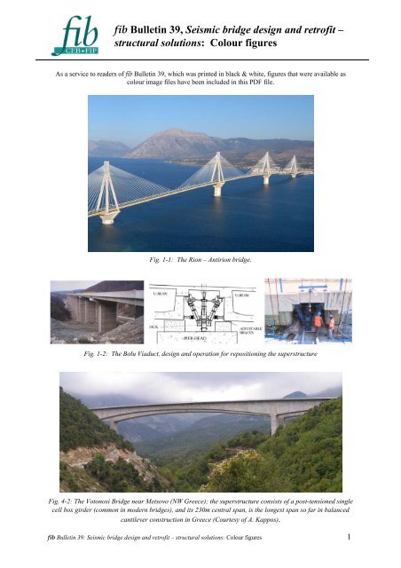
<strong>fib</strong> <strong>Bulletin</strong> <strong>39</strong>, <strong>Seismic</strong> <strong>bridge</strong> <strong>design</strong> <strong>and</strong> <strong>retrofit</strong> <strong>–</strong><br />
<strong>structural</strong> <strong>solutions</strong>: Colour figures<br />
As a service to readers of <strong>fib</strong> <strong>Bulletin</strong> <strong>39</strong>, which was printed in black & white, figures that were available as<br />
colour image files have been included in this PDF file.<br />
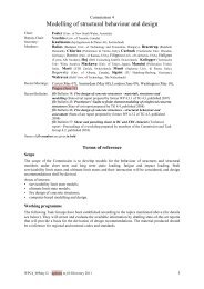
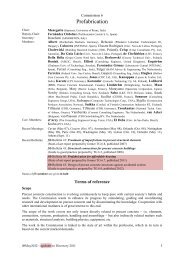
Fig. 1-1: The Rion <strong>–</strong> Antirion <strong>bridge</strong>.<br />
Fig. 1-2: The Bolu Viaduct, <strong>design</strong> <strong>and</strong> operation for repositioning the superstructure<br />
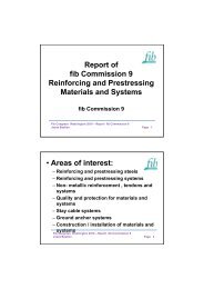
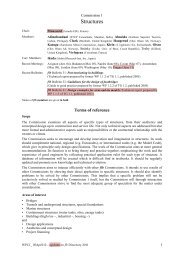
Fig. 4-2: The Votonosi Bridge near Metsovo (NW Greece); the superstructure consists of a post-tensioned single<br />
cell box girder (common in modern <strong>bridge</strong>s), <strong>and</strong> its 230m central span, is the longest span so far in balanced<br />
cantilever construction in Greece (Courtesy of A. Kappos).<br />
<strong>fib</strong> <strong>Bulletin</strong> <strong>39</strong>: <strong>Seismic</strong> <strong>bridge</strong> <strong>design</strong> <strong>and</strong> <strong>retrofit</strong> <strong>–</strong> <strong>structural</strong> <strong>solutions</strong>: Colour figures 1
Fig. 4-7: The G2 <strong>bridge</strong> near Kavala (NE Greece); the superstructure consists of precast post-tensioned beams<br />
connected through a cast in situ top slab (typical of older construction) (Courtesy of A. Kappos).<br />
Fig. 4-9: Precast segmental elements for the construction of the San Francisco-Oakl<strong>and</strong> Bay Bridge Skyway<br />
Structure (Courtesy of F. Seible)<br />
<strong>fib</strong> <strong>Bulletin</strong> <strong>39</strong>: <strong>Seismic</strong> <strong>bridge</strong> <strong>design</strong> <strong>and</strong> <strong>retrofit</strong> <strong>–</strong> <strong>structural</strong> <strong>solutions</strong>: Colour figures 2
Fig. 4-10: Example of use of the use of precast I-girders on a highway <strong>bridge</strong>-widening project in California<br />
(Courtesy of J. Restrepo)<br />
Fig. 4-12: Use of a ‘pre-shaft’ to increase the pier length in an Egnatia <strong>bridge</strong> (Metsovitikos)<br />
Fig. 5-16: View of the Antirion access viaduct during construction (see pile cap above ground surface)<br />
<strong>fib</strong> <strong>Bulletin</strong> <strong>39</strong>: <strong>Seismic</strong> <strong>bridge</strong> <strong>design</strong> <strong>and</strong> <strong>retrofit</strong> <strong>–</strong> <strong>structural</strong> <strong>solutions</strong>: Colour figures 3
Fig. 6-5: The Thjorsa <strong>bridge</strong> in the South Icel<strong>and</strong> Lowl<strong>and</strong>s (mceer.buffalo.edu).<br />
Fig. 6-8: Section of a Laminated (left) <strong>and</strong> Lead (right) Rubber Bearings.<br />
Fig. 6-18: C-shaped Device (left) <strong>and</strong> EDU Device (right).<br />
<strong>fib</strong> <strong>Bulletin</strong> <strong>39</strong>: <strong>Seismic</strong> <strong>bridge</strong> <strong>design</strong> <strong>and</strong> <strong>retrofit</strong> <strong>–</strong> <strong>structural</strong> <strong>solutions</strong>: Colour figures 4
Fig. 6-19: View of the Bolu Viaduct (Priestley <strong>and</strong> Calvi, 2003) (left) <strong>and</strong> detail of the pier top (Marioni, ALGA<br />
S.p.A.) (right).<br />
Fig. 6-25: Representation of the viscous damper units in the Rion-Antirion <strong>bridge</strong> (http://www.gefyra.gr) (left),<br />
example of viscous dampers application to a <strong>bridge</strong> located at Yen-Chou in Taiwan (Hwang <strong>and</strong> Tseng, 2005)<br />
(right).<br />
Fig. 6-33: Double-ended MR damper (left) <strong>and</strong> MR piloted hydraulic damper (right).<br />
<strong>fib</strong> <strong>Bulletin</strong> <strong>39</strong>: <strong>Seismic</strong> <strong>bridge</strong> <strong>design</strong> <strong>and</strong> <strong>retrofit</strong> <strong>–</strong> <strong>structural</strong> <strong>solutions</strong>: Colour figures 5
Fig. 6-34: ER Dampers: linear (left) <strong>and</strong> rotating (right) working schemes (Marioni, 2002).<br />
Fig. 8-1: Wushi Bridge - fault movement between<br />
piers 2 <strong>and</strong> 3<br />
Fig. 8-2: Wushi Bridge - span collapse due to<br />
longitudinal movement at pier P2N<br />
Fig. 8-3: Wushi Bridge - shear failure of pier P2S Fig. 8-4: Wushi Bridge - settlement <strong>and</strong> shear<br />
cracks at pier P3N<br />
<strong>fib</strong> <strong>Bulletin</strong> <strong>39</strong>: <strong>Seismic</strong> <strong>bridge</strong> <strong>design</strong> <strong>and</strong> <strong>retrofit</strong> <strong>–</strong> <strong>structural</strong> <strong>solutions</strong>: Colour figures 6
Fig, 8-5: Bolu Viaduct - view from abutment S2<br />
Fig. 8-7: Bolu Viaduct - failure of an EDU Fig. 8-8: Bolu Viaduct - unseating of beam end at<br />
pier cap<br />
Fig. 8-13: Extended seating frame<br />
Fig. 8-14: Extended seating frame<br />
<strong>fib</strong> <strong>Bulletin</strong> <strong>39</strong>: <strong>Seismic</strong> <strong>bridge</strong> <strong>design</strong> <strong>and</strong> <strong>retrofit</strong> <strong>–</strong> <strong>structural</strong> <strong>solutions</strong>: Colour figures 7
Fig. 8-15: Abutment with extended seating length <strong>and</strong> special bearings<br />
Fig. 8-16: Piers with extended seating length <strong>and</strong> special bearings<br />
Fig. 8-17: Steel <strong>bridge</strong> <strong>and</strong> in-situ concrete <strong>bridge</strong>s.<br />
<strong>fib</strong> <strong>Bulletin</strong> <strong>39</strong>: <strong>Seismic</strong> <strong>bridge</strong> <strong>design</strong> <strong>and</strong> <strong>retrofit</strong> <strong>–</strong> <strong>structural</strong> <strong>solutions</strong>: Colour figures 8
Fig. 9-10: Road system of Shelby County [Werner (2004)]<br />
Fig. 9-12: State of the <strong>bridge</strong>s in the road system of Shelby County [Werner (2000)]<br />
Figure 10-1: Span collapses at the Golden State-Antelope Valley interchange collectors during the 1971 San<br />
Fern<strong>and</strong>o (left) <strong>and</strong> the 1994 Northridge (right) earthquakes (courtesy of USGS).<br />
<strong>fib</strong> <strong>Bulletin</strong> <strong>39</strong>: <strong>Seismic</strong> <strong>bridge</strong> <strong>design</strong> <strong>and</strong> <strong>retrofit</strong> <strong>–</strong> <strong>structural</strong> <strong>solutions</strong>: Colour figures 9
Fig. 10-2: Punching of piles through the road bed of the State Route 1, Watsonville area, span during the 1989<br />
Loma Prieta earthquake (after NISEE, 2000).<br />
Fig. 10-3: Pounding damage: between adjacent spans at the Interstate-5 at Santa Clara River in Los Angeles<br />
County during the 1994 Northridge earthquake (left) <strong>and</strong> at the abutment of a <strong>bridge</strong> near Nishinomiya Port in<br />
the 1995 Kobe earthquake (after NISEE, 2000).<br />
Fig. 10-4: Confinement failure at <strong>bridge</strong> pier top during the 1994 Northridge earthquake (after NISEE, 2000).<br />
<strong>fib</strong> <strong>Bulletin</strong> <strong>39</strong>: <strong>Seismic</strong> <strong>bridge</strong> <strong>design</strong> <strong>and</strong> <strong>retrofit</strong> <strong>–</strong> <strong>structural</strong> <strong>solutions</strong>: Colour figures 10
Fig. 10-5: Flexural failure above column base of columns of the Hanshin expressway, due to premature<br />
termination of longitudinal reinforcement <strong>and</strong> inadequate confinement in the 1995 Kobe earthquake (courtesy of<br />
Kawashima).<br />
Fig. 10-6: Shear failure within (left) <strong>and</strong> outside (right) the plastic hinge region in San Fern<strong>and</strong>o Mission Blvd-<br />
Gothic Avenue Bridge <strong>and</strong> I-10 Freeway at Venice Blvd, respectively, during the 1994 Northridge earthquake<br />
(after NISEE, 2000).<br />
Fig. 10-7: Different shear damage patterns for RC piers at the under-crossing of the Santa-Monica Interstate 10<br />
during the 1994 Northridge earthquake: Piers # 5 with inadequate detailing for plastic hinge (left), Piers # 6<br />
with symmetric buckling (middle) <strong>and</strong> Pier # 8 with typical shear failure (right) (after Broderick et al., 1994).<br />
<strong>fib</strong> <strong>Bulletin</strong> <strong>39</strong>: <strong>Seismic</strong> <strong>bridge</strong> <strong>design</strong> <strong>and</strong> <strong>retrofit</strong> <strong>–</strong> <strong>structural</strong> <strong>solutions</strong>: Colour figures 11
Fig. 10-8: Sliding shear at top columns of the Cypress viaduct in the 1989 Loma Prieta earthquake (after<br />
NISEE, 2000).<br />
Fig. 10-22: Typical European viaduct.<br />
Fig. 10-23: Elastic spectra (left) <strong>and</strong> hazard function (right).<br />
<strong>fib</strong> <strong>Bulletin</strong> <strong>39</strong>: <strong>Seismic</strong> <strong>bridge</strong> <strong>design</strong> <strong>and</strong> <strong>retrofit</strong> <strong>–</strong> <strong>structural</strong> <strong>solutions</strong>: Colour figures 12
Effective strain, %<br />
10 0<br />
10 -1<br />
10 -2<br />
10 -3<br />
10<br />
0 0.1 0.2 0.3<br />
-4<br />
Surface PGA,g<br />
G/G 0<br />
1<br />
0.8<br />
0.6<br />
0.4<br />
0.2<br />
Proposed<br />
FEMA-368<br />
Proposed<br />
Soft soil<br />
Stiff soil<br />
Very stiff soil<br />
0<br />
0 0.2 0.4 0.6 0.8 1<br />
Surface PGA,g<br />
Fig. 10-25: Surface PGA <strong>and</strong> effective strain of the soft soil deposit (left) <strong>and</strong> surface PGA versus G/G0 (right).<br />
Drift ratio, %<br />
2.5<br />
2.0<br />
1.5<br />
1.0<br />
0.5<br />
Flexible base - total drift<br />
Flexible base - tangent drift<br />
Fixed base - drift<br />
0<br />
0 0.05 0.10 0.15 0.20 0.25 0.30 0.35<br />
PGA, g<br />
Probability of drift ratio > 0.46%<br />
1<br />
0.8<br />
0.6<br />
0.4<br />
0.2<br />
Flexible base<br />
Fixed base<br />
0<br />
0 0.05 0.1 0.15<br />
PGA, g<br />
0.2 0.25 0.3<br />
Fig. 10-26: Drifts of the SDOF system with <strong>and</strong> without SSI effects (left) <strong>and</strong> fragility curves of the SDOF<br />
(right).<br />
(a) (b)<br />
Fig. 11-2: Steel jacket <strong>retrofit</strong> of columns: (a) Los Angeles, <strong>and</strong> (b) San Francisco<br />
<strong>fib</strong> <strong>Bulletin</strong> <strong>39</strong>: <strong>Seismic</strong> <strong>bridge</strong> <strong>design</strong> <strong>and</strong> <strong>retrofit</strong> <strong>–</strong> <strong>structural</strong> <strong>solutions</strong>: Colour figures 13
Fig. 11-3: Steel jacket <strong>retrofit</strong> at Metropolitan<br />
Expressway<br />
Fig. 11-4: Steel jacket <strong>retrofit</strong> at Hanshin Expressway in<br />
1989, which was effective during the 1995 Kobe earthquake<br />
Fig. 11-9: Test models (9m tall <strong>and</strong> 2.5m x 2.5m section) for steel jacketing with controlled<br />
enhancement of flexural capacity<br />
Fig. 11-12: Steel jacket <strong>retrofit</strong> for frame piers, Metropolitan Expressway, Japan<br />
<strong>fib</strong> <strong>Bulletin</strong> <strong>39</strong>: <strong>Seismic</strong> <strong>bridge</strong> <strong>design</strong> <strong>and</strong> <strong>retrofit</strong> <strong>–</strong> <strong>structural</strong> <strong>solutions</strong>: Colour figures 14
Fig. 11-13: Engagement joint (Courtesy of JR Research Institute)<br />
Effective Use of Engagement Joint for Steel Jacket<br />
Courtesy of Japan Railway<br />
Fig. 11-14: Effective use of engagement joint for <strong>retrofit</strong> at a railway viaduct (JR Research Institute)<br />
(a) (b) (c)<br />
Fig. 11-15: Steel jacket repair <strong>and</strong> <strong>retrofit</strong> for shear; (a) shear failure after loaded, (b) repaired by steel<br />
jacketing, <strong>and</strong> (c) flexural failure of <strong>retrofit</strong>ted column (after steel jacket was removed) [Iwata et al. (2001)]<br />
<strong>fib</strong> <strong>Bulletin</strong> <strong>39</strong>: <strong>Seismic</strong> <strong>bridge</strong> <strong>design</strong> <strong>and</strong> <strong>retrofit</strong> <strong>–</strong> <strong>structural</strong> <strong>solutions</strong>: Colour figures 15
(a) (b)<br />
Fig. 11-20: Cyclic loading test on the <strong>retrofit</strong> of wall pier by steel jacket covered by reinforced concrete jacket<br />
with cross aramid <strong>fib</strong>er reinforced plastics rods: (a) As-built pier, <strong>and</strong> (b) Pier <strong>retrofit</strong>ted using cross aramid<br />
<strong>fib</strong>er reinforced plastics rods [Tamaoki et al. (1996)]<br />
(a)<br />
(b) (c)<br />
Fig. 11-21: Retrofit using cross aramid <strong>fib</strong>er reinforced plastics rods to wall piers: steel jacketing, (b) set of<br />
cross aramid <strong>fib</strong>er reinforced plastics rods, <strong>and</strong> (c) after <strong>retrofit</strong>ted (courtesy of Sumitomo Mitsui Construction)<br />
<strong>fib</strong> <strong>Bulletin</strong> <strong>39</strong>: <strong>Seismic</strong> <strong>bridge</strong> <strong>design</strong> <strong>and</strong> <strong>retrofit</strong> <strong>–</strong> <strong>structural</strong> <strong>solutions</strong>: Colour figures 16
R i i t d<br />
ƒCƒgƒ‹<br />
•<br />
(a) (b) c)<br />
Fig. 11-23: Wrapping of carbon <strong>fib</strong>er sheet: (a) pasting glue, (b) wrapping the first layer, <strong>and</strong><br />
(c) bonding on the first layer<br />
(a) (b)<br />
ƒ^ƒ<br />
Fig. 11-27: Carbon <strong>fib</strong>er sheet jacketing of hollow reinforced concrete columns, Sakawa-gawa <strong>bridge</strong>, Tomei<br />
expressway; (a) Retrofitted east- <strong>and</strong> west-bound <strong>bridge</strong>, <strong>and</strong> (b) Wrapping of carbon <strong>fib</strong>er sheets [Ogata et al.<br />
(1999), Osada et al. (1999)]<br />
W rapping of Aram id Fiber Reinforced Plastics Sheet<br />
Courtesy of Japan Railway<br />
Mortar Cover on the Aramid Fiber Reinforced<br />
Plastics Sheet Jacket<br />
Courtesy of Japan Railway<br />
Fig. 11-30: Aramid <strong>fib</strong>er reinforced plastics jacketing for a railway viaduct [courtesy of JR Research Institute]<br />
<strong>fib</strong> <strong>Bulletin</strong> <strong>39</strong>: <strong>Seismic</strong> <strong>bridge</strong> <strong>design</strong> <strong>and</strong> <strong>retrofit</strong> <strong>–</strong> <strong>structural</strong> <strong>solutions</strong>: Colour figures 17<br />
<strong>–</strong>{
Fig. 11-31: Piers <strong>retrofit</strong>ted by aramid <strong>fib</strong>er sheet [Kato et al. (2001)]<br />
(a) (b)<br />
Fig. 11-33: Rectangular column with glass <strong>fib</strong>er-epoxy rectangular jacket: (a) failure by jacket fracture, (b)<br />
lateral force-displacement response [Priestley, Seible <strong>and</strong> Calvi (1996)]<br />
Fiber Reinforced Plastic Jacket<br />
Blast of Glass Fiber + Resin<br />
Japan Railway<br />
Courtesy of Japan Railway<br />
Fig. 11-34: Glass <strong>fib</strong>er jacketing (courtesy of JR Research Institute)<br />
<strong>fib</strong> <strong>Bulletin</strong> <strong>39</strong>: <strong>Seismic</strong> <strong>bridge</strong> <strong>design</strong> <strong>and</strong> <strong>retrofit</strong> <strong>–</strong> <strong>structural</strong> <strong>solutions</strong>: Colour figures 18
Fig. 11-35: Precast concrete segment jacket [courtesy of PS Concrete]<br />
Fig. 11-36: On-site loading test on the effectiveness of PC segment jacketing<br />
(a) before <strong>retrofit</strong> (b) after <strong>retrofit</strong><br />
Fig. 11-37: Columns <strong>retrofit</strong>ted by PC segment jacket: (a) as-built <strong>and</strong> (b) after <strong>retrofit</strong> (courtesy of Kawada<br />
Construction)<br />
<strong>fib</strong> <strong>Bulletin</strong> <strong>39</strong>: <strong>Seismic</strong> <strong>bridge</strong> <strong>design</strong> <strong>and</strong> <strong>retrofit</strong> <strong>–</strong> <strong>structural</strong> <strong>solutions</strong>: Colour figures 19
(a) (b)<br />
(c) (d)<br />
Fig. 11-42: Retrofit of wall pier by PC segment jacket: (a) as-built pier, (b) set of a precast segment using<br />
temporary joints, (c) anchor bolt for confinement (up) <strong>and</strong> anchor bolt for footing (bottom), <strong>and</strong> (d) after<br />
<strong>retrofit</strong>ted (courtesy of Maeda Construction)<br />
(a) (b)<br />
Fig. 11-43: Collapse of Cypress viaduct (Courtesy of Caltrans)<br />
<strong>fib</strong> <strong>Bulletin</strong> <strong>39</strong>: <strong>Seismic</strong> <strong>bridge</strong> <strong>design</strong> <strong>and</strong> <strong>retrofit</strong> <strong>–</strong> <strong>structural</strong> <strong>solutions</strong>: Colour figures 20
(a) (b)<br />
(c) (d)<br />
(e) (f)<br />
Fig. 11-46: Retrofit of San Francisco double-deck viaducts using edge link beams: (a) as-built viaduct, (b)<br />
proof test model, (c) proof test, (d) column damage in the proof test, (d) <strong>retrofit</strong>, <strong>and</strong> (e) edge beams [(a)-(d):<br />
Priestley, Seible <strong>and</strong> Calvi (1996)]<br />
<strong>fib</strong> <strong>Bulletin</strong> <strong>39</strong>: <strong>Seismic</strong> <strong>bridge</strong> <strong>design</strong> <strong>and</strong> <strong>retrofit</strong> <strong>–</strong> <strong>structural</strong> <strong>solutions</strong>: Colour figures 21
(a)<br />
(b) (c)<br />
Fig. 11-52: Footing <strong>retrofit</strong>: (a) extension of footing <strong>and</strong> new piles (California, USA), (b) extension of footing<br />
<strong>and</strong> new piles (Japan), <strong>and</strong> (c) Overlay of footing (Japan)<br />
<strong>fib</strong> <strong>Bulletin</strong> <strong>39</strong>: <strong>Seismic</strong> <strong>bridge</strong> <strong>design</strong> <strong>and</strong> <strong>retrofit</strong> <strong>–</strong> <strong>structural</strong> <strong>solutions</strong>: Colour figures 22
(a) (b)<br />
Fig.11-54: Retrofit of a footing using aramid <strong>fib</strong>er reinforced plastic rods: (a) as-built <strong>bridge</strong>, (b) aramid <strong>fib</strong>er<br />
reinforced plastic rods, <strong>and</strong> (c) aramid <strong>fib</strong>er reinforced plastic rods installed in the footing in the vertical<br />
direction [courtesy of Sumitomo Mitsui Construction]<br />
(c)<br />
(a) (b)<br />
Fig. 11-55: Implementation of steel segment dry-up method: (a) assembling test, <strong>and</strong> (b) assembling the<br />
segments around the foundation [courtesy of Obayashi Construction]<br />
<strong>fib</strong> <strong>Bulletin</strong> <strong>39</strong>: <strong>Seismic</strong> <strong>bridge</strong> <strong>design</strong> <strong>and</strong> <strong>retrofit</strong> <strong>–</strong> <strong>structural</strong> <strong>solutions</strong>: Colour figures 23
(a) (b)<br />
Fig. 11-57: Micro piles for <strong>retrofit</strong> of foundations: (a) drilling <strong>and</strong> (b) micro piles after installation<br />
[Nishitani et al. (2002)]<br />
Fig. 11-61: Damage of intermediate joint due to pounding (1994 Northridge earthquake)<br />
(a) (b)<br />
Fig. 11-62: Installation of cable restrainers (courtesy of California Department of Transportation)<br />
<strong>fib</strong> <strong>Bulletin</strong> <strong>39</strong>: <strong>Seismic</strong> <strong>bridge</strong> <strong>design</strong> <strong>and</strong> <strong>retrofit</strong> <strong>–</strong> <strong>structural</strong> <strong>solutions</strong>: Colour figures 24
(a) (b)<br />
Fig. 11-67: <strong>Seismic</strong> <strong>retrofit</strong> using isolation: (a) installation of lead rubber bearings <strong>and</strong> sliding bearings, <strong>and</strong><br />
(b) after <strong>retrofit</strong> (courtesy of Japan Highway Public Corporation)<br />
(a) (b)<br />
Fig. 11-68: Connection of decks <strong>and</strong> <strong>retrofit</strong>: (a) removal of existing steel bearings, <strong>and</strong> (b) set of new lead<br />
rubber bearing (courtesy of Hanshin Expressway Public Corporation)<br />
Fig. 11-71: Shake table test for the effectiveness of compression damper brace [Yoshida et al. (2005)]<br />
<strong>fib</strong> <strong>Bulletin</strong> <strong>39</strong>: <strong>Seismic</strong> <strong>bridge</strong> <strong>design</strong> <strong>and</strong> <strong>retrofit</strong> <strong>–</strong> <strong>structural</strong> <strong>solutions</strong>: Colour figures 25
Fig. 11-73: Viaduct <strong>retrofit</strong>ted using compression brace damper [Yoshida et al. (2005)]<br />
(a) (b)<br />
(c) (d)<br />
Fig. 11-76: Retrofit of a simply supported <strong>bridge</strong> using pipe arches: (a) before <strong>retrofit</strong>, (b) after <strong>retrofit</strong>, (c)<br />
pipe arches, <strong>and</strong> (d) connection between arches <strong>and</strong> a foundation [Mizuta <strong>and</strong> Hashimoto (2001)]<br />
<strong>fib</strong> <strong>Bulletin</strong> <strong>39</strong>: <strong>Seismic</strong> <strong>bridge</strong> <strong>design</strong> <strong>and</strong> <strong>retrofit</strong> <strong>–</strong> <strong>structural</strong> <strong>solutions</strong>: Colour figures 26