Eaton EX 2200-3000VA Product Manual - Fusion Power System
Eaton EX 2200-3000VA Product Manual - Fusion Power System
Eaton EX 2200-3000VA Product Manual - Fusion Power System

You also want an ePaper? Increase the reach of your titles
YUMPU automatically turns print PDFs into web optimized ePapers that Google loves.
www.eaton.com<br />
Pulsar Series<br />
<strong>EX</strong><br />
<strong>2200</strong> RT 2U<br />
<strong>2200</strong> RT 3U<br />
3000 RT 2U<br />
3000 RT 3U<br />
3000 RT 3U XL<br />
<strong>EX</strong>B RT 3U<br />
Installation and user<br />
manual<br />
English<br />
Français<br />
Deutsch<br />
Italiano<br />
Español<br />
Nederlands
3400777600/AD
Environmental protection<br />
Thank you for selecting an EATON product to protect your electrical equipment.<br />
EATON has implemented an environmental-protection policy.<br />
<strong>Product</strong>s are developed according to an eco-design approach.<br />
Substances<br />
This product does not contain CFCs, HCFCs or asbestos.<br />
Packing<br />
To improve waste treatment and facilitate recycling, separate the various packing components.<br />
◗ The cardboard we use comprises over 50% of recycled cardboard.<br />
◗ Sacks and bags are made of polyethylene.<br />
◗ Packing materials are recyclable and bear the appropriate identification symbol .<br />
Follow all local regulations for the disposal of packing materials.<br />
End of life<br />
Introduction<br />
The <strong>EX</strong> range has been designed with the utmost care.<br />
We recommend that you take the time to read this manual to take full advantage of the many features of your UPS<br />
(Uninterruptible <strong>Power</strong> <strong>System</strong>).<br />
Before installing <strong>EX</strong>, please read the booklet on the required safety instructions. Then follow the indications in this<br />
manual.<br />
To discover the entire range of EATON products and the options available for the <strong>EX</strong> range, we invite you to visit our<br />
web site at www.eaton.com or contact your EATON representative.<br />
Material Abbreviation Symbol<br />
number<br />
Polyethylene terephthalate PET 01<br />
High-density polyethylene HDPE 02<br />
Polyvinyl chloride PVC 03<br />
Low-density polyethylene LDPE 04<br />
Polypropylene PP 05<br />
Polystyrene PS 06<br />
EATON will process products at the end of their service life in compliance with local regulations.<br />
EATON works with companies in charge of collecting and eliminating our products at the end of their service life.<br />
<strong>Product</strong><br />
The product is made up of recyclable materials.<br />
Dismantling and destruction must take place in compliance with all local regulations concerning waste.<br />
At the end of its service life, the product must be transported to a processing centre for electrical and electronic waste.<br />
Battery<br />
The product contains lead-acid batteries that must be processed according to applicable local regulations concerning<br />
batteries.<br />
The battery may be removed to comply with regulations and in view of correct disposal.<br />
34007776EN/AD - Page 3
Introduction<br />
Pictograms<br />
34007776EN/AD - Page 4<br />
Important instructions that must always be followed.<br />
Information, advice, help.<br />
Visual indication.<br />
Action.<br />
Audio signal.<br />
In the illustrations on the following pages, the symbols below are used:<br />
LED off<br />
LED on<br />
LED flashing
1. Presentation<br />
Contents<br />
1.1 Standard positions ...................................................................................................................... 6<br />
Tower position................................................................................................................................ 6<br />
Rack position.................................................................................................................................. 6<br />
1.2 Rear panels ................................................................................................................................... 7<br />
<strong>EX</strong> <strong>2200</strong> / 3000 .............................................................................................................................. 7<br />
<strong>EX</strong> <strong>EX</strong>B (optional battery module) .................................................................................................. 7<br />
1.3 Control panel................................................................................................................................ 7<br />
2. Installation<br />
2.1 Unpacking and contents check................................................................................................... 8<br />
2.2 Installation in tower position...................................................................................................... 9<br />
2.3 Installation in rack position ........................................................................................................ 9<br />
2.4 Communication ports.................................................................................................................10<br />
Connection of RS232 or USB communication port (optional) .......................................................10<br />
Installation of the communication cards (optional) .......................................................................10<br />
2.5 Connection with a FlexPDU (<strong>Power</strong> Distribution Unit) module.................................................11<br />
2.6 Connection with a HotSwap MBP module...............................................................................11<br />
HotSwap MBP-module operation .................................................................................................12<br />
2.7 UPS connection without a FlexPDU or HotSwap MBP module.............................................12<br />
3. Operation<br />
3.1 Start-up and normal operation..................................................................................................13<br />
3.2 Operation on battery power ......................................................................................................13<br />
3.3 Return of AC input power ..........................................................................................................14<br />
3.4 UPS shutdown ............................................................................................................................14<br />
3.5 Using the UPS remote control functions..................................................................................14<br />
4. Access to measurements and personalisation data<br />
4.1 Display menus arrangement......................................................................................................16<br />
4.2 Access to measurements ...........................................................................................................16<br />
4.3 Personalisation using the control panel ...................................................................................16<br />
4.4 Personalisation using external software...................................................................................17<br />
5. Maintenance<br />
5.1 Troubleshooting ..........................................................................................................................18<br />
Troubleshooting a UPS equipped with the HotSwap MBP module ..............................................19<br />
5.2 Battery-module replacement .....................................................................................................19<br />
Safety recommendations..............................................................................................................19<br />
Battery-module removal................................................................................................................19<br />
Mounting the new battery module .............................................................................................. 20<br />
5.3 Maintenance on a UPS equipped with the HotSwap MBP module...................................... 20<br />
5.4 Training centre............................................................................................................................ 21<br />
6. Appendices<br />
6.1 Technical specifications............................................................................................................. 22<br />
6.2 Glossary ...................................................................................................................................... 23<br />
34007776EN/AD - Page 5
1. Presentation<br />
1.1 Standard positions<br />
Tower position<br />
Rack position<br />
34007776EN/AD - Page 6<br />
Dimensions (H x W x D) in mm<br />
<strong>EX</strong> <strong>2200</strong> RT 2U 440 x 86 x 640<br />
<strong>EX</strong> <strong>2200</strong> RT 3U 440 x 131 x 490<br />
<strong>EX</strong> 3000 RT 2U 440 x 86 x 640<br />
<strong>EX</strong> 3000 RT 3U 440 x 131 x 490<br />
<strong>EX</strong> 3000 RT 3U XL 440 x 131 x 490<br />
<strong>EX</strong> <strong>EX</strong>B RT 3U 440 x 131 x 490<br />
Weights in kg<br />
<strong>EX</strong> <strong>2200</strong> RT 2U 31<br />
<strong>EX</strong> <strong>2200</strong> RT 3U 30<br />
<strong>EX</strong> 3000 RT 2U 31<br />
<strong>EX</strong> 3000 RT 3U 30<br />
<strong>EX</strong> 3000 RT 3U XL 17<br />
<strong>EX</strong> <strong>EX</strong>B RT 3U 42
1.2 Rear panels<br />
<strong>EX</strong> <strong>2200</strong> / 3000 / 3000 XL<br />
<strong>EX</strong> <strong>EX</strong>B (optional battery module)<br />
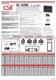
1.3 Control panel<br />
1<br />
2<br />
4 3 11 5<br />
7<br />
ESC<br />
21<br />
20 22<br />
24 25 27 26<br />
23<br />
6<br />
12 12<br />
8<br />
9 10<br />
13<br />
1. Presentation<br />
(1) USB communication port<br />
(2) RS232 communication port<br />
(3) Connector for automatic recognition of<br />
an additional battery module<br />
(4) Slot for optional communication card<br />
(5) Connector for remote ON/OFF and RPO<br />
(Remote <strong>Power</strong> Off) control<br />
(6) Connector for additional battery<br />
module<br />
(7) 16 A outlet for connection of equipment<br />
(8) Two groups of 2 programmable outlets<br />
for connection of equipment<br />
(9) Groups of 4 outlets for connection of<br />
equipment<br />
(10) Socket for connection to AC-power<br />
source<br />
(11) LED (SWF) indicating distribution<br />
system phase/neutral reversal<br />
(12) Connectors for battery modules (to<br />
the UPS or to the other battery modules)<br />
(13) Connectors for automatic recognition<br />
of battery modules<br />
(20) Load protected LED<br />
(21) Downgraded operation LED<br />
(22) Load not protected LED<br />
(23) Alphanumeric display<br />
(24) Escape (cancel) button<br />
(25) Scroll button<br />
(26) Enter (confirm) button<br />
(27) ON/OFF button for UPS and outlets<br />
34007776EN/AD - Page 7
2. Installation<br />
2.1 Unpacking and contents check<br />
34007776EN/AD - Page 8<br />
(30) <strong>EX</strong> <strong>2200</strong> / 3000 / 3000 XL UPS<br />
(31) connection cable to AC-power source<br />
(32) 2 connection cables for the protected equipment<br />
(33) RS232 communication cable<br />
(34) USB communication cable<br />
(35) 2 systems to secure power plugs<br />
(36) Solution-Pac CD-ROM<br />
(37) Documentation<br />
Elements supplied depending on the version or optional<br />
(38) Mounting kit for 19-inch bays<br />
(39) 2 supports for the upright position (2U version only)<br />
(40) FlexPDU module (optional)<br />
(41) connection cable between FlexPDU module and UPS<br />
(42) NMC communication card (optional)<br />
(43) HotSwap MBP module (optional)<br />
(44) connection cables between HotSwap MBP module<br />
and UPS<br />
Packing materials must be disposed of in compliance with all local regulations concerning waste.<br />
Recycling symbols are printed on the packing materials to facilitate sorting.
2.2 Installation in tower position<br />
2.3 Installation in rack position<br />
It is advised to first install the battery module, then the power module above.<br />
Follow steps 1 to 4 for module mounting on the rails.<br />
The rails and necessary hardware are supplied by EATON.<br />
2. Installation<br />
34007776EN/AD - Page 9
2. Installation<br />
2.4 Communication ports<br />
Connection of RS232 or USB communication port (optional)<br />
Installation of the communication cards (optional)<br />
34007776EN/AD - Page 10<br />
The RS232 and USB communication ports cannot operate simultaneously.<br />
2<br />
1<br />
4<br />
34<br />
33<br />
Communication card slot<br />
(restricted access)<br />
1 - Connect the RS232 (33) or USB (34)<br />
communication cable to the serial or USB<br />
port on the computer equipment.<br />
2 - Connect the other end of the<br />
communication cable (33) or (34) to the<br />
USB (1) or RS232 (2) communication port<br />
on the UPS.<br />
The UPS can now communicate with<br />
EATON power management software.<br />
It is not necessary to shutdown the UPS<br />
before installing a communication card.<br />
1 - Remove the UPS cover (4) secured by<br />
screws.<br />
2 - Insert the communication card in the<br />
slot.<br />
3 - Put the UPS cover back in place using<br />
the screws.
2.5 Connections with a FlexPDU (<strong>Power</strong> Distribution Unit) module (optional)<br />
FlexPDU<br />
45<br />
2.6 Connections with a HotSwap MBP module (optional)<br />
2. Installation<br />
1 - Connect the UPS socket (10) to the ACpower<br />
source using the cable (31)<br />
supplied.<br />
2 - Connect the input socket on the<br />
FlexPDU module (48) to the UPS outlet (7)<br />
using the cable (41) supplied. The cable<br />
and the connectors are marked in red.<br />
3 - Connect the equipment to the outlets<br />
(45), (46) and (47) on the FlexPDU module.<br />
These outlets differ, depending on the<br />
version of the FlexPDU module.<br />
4 - Fit the connection securing system that<br />
prevents the plugs from being pulled out<br />
accidentally.<br />
The HotSwap MBP module makes it possible to service or even replace the UPS without affecting the connected<br />
loads (HotSwap function).<br />
HotSwap MBP<br />
49<br />
UPS ON -<br />
OK to switch<br />
7<br />
7<br />
By-pass<br />
Normal<br />
46<br />
BY PASS SWITCH<br />
41<br />
50 51 52 53 54<br />
8<br />
9 10<br />
8<br />
31<br />
47<br />
9 10<br />
44<br />
55<br />
31<br />
48<br />
56<br />
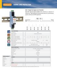
1 - Connect the input socket (56) on the<br />
HotSwap MBP module to the AC-power<br />
source using the cable (31) supplied.<br />
2 - Connect the UPS input socket (10) to<br />
the "UPS Input" (55) on the HotSwap MBP<br />
module, using the cable (44) supplied.<br />
These cables and the connectors are<br />
marked blue.<br />
3 - Connect the UPS outlet (7) to the "UPS<br />
Output" (54) on the HotSwap MBP<br />
module, using the cable (44) supplied.<br />
These cables and the connectors are<br />
marked red.<br />
4 - Connect the equipment to the outlets<br />
(49) and (50) on the HotSwap MBP<br />
module. These outlets differ, depending<br />
on the version of the HotSwap MBP<br />
module.<br />
Caution. Do not use UPS outlets (8) and<br />
(9) to supply equipment because use of<br />
switch (53) on the HotSwap MBP module<br />
would cut supply to the equipment. It is<br />
advised not to remove the protective film<br />
from outlets (8) and (9).<br />
34007776EN/AD - Page 11
2. Installation<br />
HotSwap MBP-module operation<br />
34007776EN/AD - Page 12<br />
UPS ON -<br />
OK to switch<br />
By-pass<br />
Normal<br />
51 52 53<br />
UPS start-up with the HotSwap MBP module<br />
1 - Check that the UPS is correctly connected to the HotSwap MBP module.<br />
2 - Set switch (53) to the Normal position.<br />
3 - Start the UPS by pressing the ON/OFF button (27) on the UPS control panel.<br />
The load is supplied by the UPS.<br />
LED (51) "UPS ON - OK to switch" on the HotSwap MBP module goes ON.<br />
HotSwap MBP-module test<br />
1 - Set switch (53) to the Bypass position and check that the load is still supplied.<br />
2 - Set switch (53) back to the Normal position.<br />
2.7 UPS connection without a FlexPDU or HotSwap MBP module<br />
The HotSwap MBP module has a rotary<br />
switch (53) with two positions:<br />
Normal - the load is supplied by the UPS,<br />
Bypass - the load is supplied directly by<br />
the AC-power source.<br />
Check that the indications on the name plate located on the back of the UPS correspond to the AC-power source<br />
and the true electrical consumption of the total load.<br />
7<br />
9<br />
10<br />
BY PASS SWITCH<br />
8<br />
31<br />
35<br />
1 - Connect the supplied cable (31) (250 V -<br />
16 A) to the socket (10), then to the ACpower<br />
source.<br />
2 - Connect the loads to the UPS using the<br />
cables (32).<br />
It is preferable to connect the priority loads<br />
to the four outlets marked (9) and the nonpriority<br />
loads to the four outlets marked (8)<br />
that can be programmed in pairs (1 and 2).<br />
Connect any high-power devices to the 16<br />
A outlet (7).<br />
To program shutdown of outlets (8) during<br />
operation on battery power and thus<br />
optimise the available backup time, the<br />
EATON communication software is<br />
required.<br />
3 - Fit the connection securing system (35)<br />
that prevents the plugs from being pulled<br />
out accidentally.<br />
Note. The UPS charges the battery as soon as it is connected to the AC-power source, even if button (27) is not<br />
pressed.<br />
Once the UPS is connected to the AC-power source, eight hours of charging are required before the battery can<br />
supply the rated backup time.<br />
<strong>EX</strong> 3000 XL: at least one additionnal <strong>EX</strong>B battery module must be connected to the UPS because it does not have<br />
internal batteries.<br />
Refer to <strong>EX</strong>B battery module installation manual (doc n° 34008167) for further information about connections.<br />
32
3.1 Start-up and normal operation<br />
UPS personalisation<br />
3.2 Operation on battery power<br />
Transfer to battery power<br />
Low-battery warning<br />
3. Operation<br />
For the initial start, AC input power must be present to detect any wiring errors. Subsequently, the UPS can start even<br />
if AC input power is not present.<br />
ESC<br />
Press button (27) for approximately 1 second.<br />
◗ The buzzer beeps once and all the LEDs go ON simultaneously.<br />
◗ The buzzer then beeps twice during the self-test, then button (27)<br />
remains ON, indicating that the load outputs are supplied.<br />
The connected devices are protected by the UPS.<br />
◗ LED (20) is ON.<br />
If LED (22) is ON, a fault has occurred (see the "Troubleshooting"<br />
section).<br />
◗ During normal operation, the scroll button (25) may be used to read<br />
UPS measurements (voltage on normal and bypass AC inputs,<br />
operating mode, battery capacity and UPS serial number).<br />
If UPS personalisation is desired, it is advised to enter the personalisation mode at this time.<br />
This mode may be entered using the buttons on the control panel or the Personal Solution-Pac software (Windows)<br />
included on the Solution-Pac CD-ROM provided by EATON.<br />
ESC<br />
ESC<br />
20<br />
21<br />
22<br />
25<br />
27<br />
20<br />
21<br />
20<br />
21<br />
◗ The connected devices continue to be supplied by the UPS when AC<br />
input power is no longer available. The necessary energy is provided<br />
by the battery.<br />
◗ LEDs (20) and (21) go ON.<br />
◗ The audio alarm beeps every ten seconds.<br />
The connected devices are supplied by the battery.<br />
The display indicates the remaining backup time.<br />
◗ LEDs (20) and (21) go ON.<br />
◗ The audio alarm beeps every three seconds.<br />
The remaining battery power is low.<br />
Shut down all applications on the connected equipment because<br />
automatic UPS shutdown is imminent.<br />
34007776EN/AD - Page 13
3. Operation<br />
34007776EN/AD - Page 14<br />
End of battery backup time<br />
3.3 Return of AC input power<br />
3.4 UPS shutdown<br />
◗ All the LEDs go OFF.<br />
◗ The audio alarms stops.<br />
The UPS is completely shut down.<br />
Following an outage, the UPS restarts automatically when AC input power returns (unless the restart function was<br />
disabled via UPS personalisation) and the load is again supplied.<br />
3.5 Using the UPS remote control functions<br />
<strong>EX</strong> offers a choice between two remote control functions.<br />
◗ RPO: Remote <strong>Power</strong> Off allows a remote contact to be used to disconnect all the equipment connected to the UPS.<br />
Restarting the UPS requires manual intervention.<br />
◗ ROO: Remote ON/OFF allows remote action of button (27) to shut down the UPS.<br />
These functions are obtained by opening a contact connected between the appropriate pins of connector (5) on the<br />
rear panel of the UPS (see diagram on figures below).<br />
5<br />
ESC<br />
20<br />
21<br />
22<br />
27<br />
Remote control connection and test<br />
Press button (27) for approximately 2 seconds.<br />
The devices connected to the UPS are no longer supplied.<br />
1 - Check that the UPS is off and disconnected from the AC input source.<br />
2 - Remove connector (5) after unscrewing the screws.<br />
3 - Connect a normally closed volt-free contact (60 Vdc / 30 Vac max, 20 mA max, 0.75 mm² cable cross section)<br />
between the two pins of connector (5), see diagram.
5<br />
5<br />
ROO<br />
RPO<br />
3. Operation<br />
Contact open: shut down of UPS<br />
Contact closed: start-up of UPS (UPS connected to the network and network energized)<br />
Note: local On/Off control via button (27) has priority over the remote control order.<br />
Contact open: shut down of UPS<br />
To return to normal operation, deactivate the external remote shut down contact and<br />
restart the UPS using button (27).<br />
4 - Plug connector (5) into the back of the UPS.<br />
5 - Connect and restart the UPS according to the previously described procedures.<br />
6 - Activate the external remote shut down contact to test the function.<br />
Warning: this connector must only be connected to SELV (Safety Extra Low Voltage) circuits<br />
34007776EN/AD - Page 15
4. Access to measurements and personalisation data<br />
4.1 Display menus arrangement<br />
4.2 Access to measurements<br />
34007776EN/AD - Page 16<br />
Status and Alarms<br />
Status and Alarms<br />
Measurements<br />
UPS input measurements<br />
UPS output measurements<br />
Battery measurements<br />
Local personalisation<br />
Personalisation<br />
Output personalisation<br />
Press the scroll button (25) to access any status conditions and alarms, then the measurements for voltage, current,<br />
frequency, power output and battery backup time.<br />
4.3 Personalisation using the control panel<br />
ESC<br />
ON/OFF personalisation<br />
Battery personnalisation<br />
Local personalisation<br />
Function Factory setting Other available settings<br />
◗ Press the scroll button (25) several times until the personalisation<br />
menu is reached.<br />
◗ Press the Enter button (26) to access the different possibilities.<br />
◗ Finally, confirm the selection by pressing the Enter button (26)<br />
again.<br />
Language English French, Spanish, German, Italian, Dutch<br />
Audio alarm Enabled Disabled<br />
25<br />
26
4. Access to measurements and personalisation data<br />
Output personalisation<br />
Function Factory setting Other available settings Comments<br />
Output voltage (1)<br />
Frequency converter (1)<br />
(1) These parameters may be modified only when the UPS is OFF.<br />
Detailed comments are available in the Personal Solution-Pac software.<br />
ON/OFF personalisation<br />
Battery personalisation<br />
4.4 Personalisation using external software<br />
230 Volts AC 200/208/220/240 Volts AC<br />
Disabled Enabled The connected devices are never<br />
transferred to the bypass.<br />
Output frequency (1) Automatic selection 50 or 60 Hz User selectable only if the<br />
frequency-converter function is<br />
enabled.<br />
Transfer to the bypass<br />
AC input (1)<br />
Bypass AC power must<br />
be within tolerances<br />
Bypass AC power may be<br />
outside tolerances<br />
Overload level (1) 102% 50 / 70% Alarm if threshold is overrun.<br />
Function Factory setting Other available settings Comments<br />
Cold start Enabled Disabled<br />
Automatic restart Enabled Disabled The UPS restarts automatically<br />
when AC input power returns.<br />
Energy savings Disabled Enabled When function enabled, battery<br />
shuts down when power drops to<br />
5. Maintenance<br />
5.1 Troubleshooting<br />
34007776EN/AD - Page 18<br />
If LED (21) or (22) is ON, a fault or an alarm has occurred.<br />
Use the escape button (24) to stop the audio alarm.<br />
Indication Diagnostic Correction<br />
1 The UPS does not start,<br />
the alphanumeric display indicates:<br />
COLD START NOK<br />
CHECK AC WIRING<br />
2 LED (22) is ON, the SWF LED (11) at<br />
the rear of the UPS is ON.<br />
The alphanumeric display indicates:<br />
SITE WIR. FAULT<br />
CHECK AC WIRING<br />
3 LED (22) is ON,<br />
the alphanumeric display indicates:<br />
NO BATTERY<br />
CHECK CONNECTION<br />
4 LED (22) is ON,<br />
the alphanumeric display indicates:<br />
BATTERY FAULT<br />
SERV REQUIRED<br />
5 LED (21) is ON,<br />
the alphanumeric display indicates:<br />
OVERLOAD ALARM<br />
REDUCE LOAD<br />
6 LED (22) is ON,<br />
the alphanumeric display indicates:<br />
LOAD UNPROTECTED<br />
OUTPUT OVERLOAD<br />
7 LED (22) is ON,<br />
the alphanumeric display indicates:<br />
REDUCE LOAD<br />
RESTART UPS<br />
8 LED (22) is ON,<br />
the alphanumeric display indicates:<br />
OVERLOAD FAULT<br />
REDUCE LOAD<br />
9 LED (22) is ON,<br />
the alphanumeric display indicates:<br />
LOAD SHORT-CIRCU<br />
CHECK WIRING<br />
10 LED (22) is ON,<br />
the alphanumeric display indicates:<br />
INTERNAL FAULT<br />
SERV REQUIRED<br />
11 The alphanumeric display indicates:<br />
REMOTE POWER OFF<br />
RPO<br />
The AC input power is not<br />
connected or is connected to the<br />
UPS output.<br />
Phase inversion on AC input<br />
power. The UPS does not start.<br />
The battery is incorrectly<br />
connected.<br />
Check the UPS is correctly<br />
connected to the AC input power.<br />
◗ In an earthed-neutral system, to<br />
correct the wiring, disconnect and<br />
turn the AC-power outlet 180°<br />
(DIN-SCHUKO type) or call an<br />
electrician to modify the<br />
connections.<br />
◗ For all other types of system,<br />
disable the detection function.<br />
Check battery connections (see<br />
section 5.2, Battery-module<br />
replacement).<br />
A fault is detected on the battery. Replace the battery (see section<br />
5.2, Battery-module replacement).<br />
Call the after-sales support<br />
department.<br />
The load level exceeds the<br />
programmed overload level or<br />
UPS capacity.<br />
The UPS is overloaded. Devices<br />
connected to the UPS are<br />
supplied directly by the AC input<br />
source via the By-pass.<br />
After repetitive overloads, the<br />
UPS is locked in the By-pass<br />
position. Devices connected to the<br />
UPS are supplied directly by the<br />
AC input source.<br />
The UPS shut down automatically<br />
because of overload at the UPS<br />
output.<br />
The UPS has shut down<br />
automatically because of a shortcircuit<br />
at the UPS output.<br />
A UPS internal fault has occurred.<br />
There are two possible situations:<br />
◗ the load is still supplied, but<br />
directly with AC input power via<br />
the bypass,<br />
◗ the load is no longer supplied.<br />
The Remote <strong>Power</strong> Off (RPO)<br />
contact has been activated to shut<br />
down the UPS.<br />
Check the power drawn by the<br />
connected devices and disconnect<br />
any non-priority devices. Check<br />
the programmed overload level.<br />
Check the power drawn by the<br />
connected devices and disconnect<br />
any non-priority devices.<br />
Check the power drawn by the<br />
connected devices and disconnect<br />
any non-priority devices.<br />
Shut down and restart the UPS to<br />
return to normal operation.<br />
Check the power drawn by the<br />
connected devices and disconnect<br />
any non-priority devices.<br />
Check the installation at the UPS<br />
output (wiring, load equipment<br />
faults).<br />
Call the after-sales support<br />
department.<br />
Set the contact back to its the<br />
normal position, and press the ON/<br />
OFF button to restart.
Troubleshooting a UPS equipped with the HotSwap MBP module<br />
5.2 Battery-module replacement<br />
Safety recommendations<br />
Battery-module removal<br />
Indication Diagnostic Correction<br />
12 The load is no longer supplied when<br />
the rotary switch (49) on the<br />
HotSwap MBP module is set to the<br />
Bypass position.<br />
13 The load is no longer supplied when<br />
the rotary switch (49) on the<br />
HotSwap MBP module is set to the<br />
Normal position.<br />
14 The load is no longer supplied after<br />
AC-power fails.<br />
◗ The protected devices are<br />
connected to the UPS output<br />
instead of to the HotSwap MBP<br />
module.<br />
◗ The AC-power cord is connected<br />
to the UPS input instead of to the<br />
HotSwap MBP module.<br />
5. Maintenance<br />
Check the wiring between the UPS<br />
and the HotSwap MBP module<br />
(see section 2.6).<br />
◗ The UPS is shut down.<br />
◗ Start the UPS.<br />
◗ The wiring between the UPS and ◗ Check the wiring between the<br />
the HotSwap MBP module is not UPS and the HotSwap MBP<br />
correct.<br />
module (see section 2.6).<br />
◗ The rotary switch (49) on the<br />
HotSwap MBP module is set to<br />
the Bypass position.<br />
◗ The wiring between the UPS and<br />
the HotSwap MBP module is not<br />
correct.<br />
If a fault leads to UPS shutdown, press the ON/OFF button (27) to clear the fault.<br />
◗ Set the rotary switch (49) on the<br />
HotSwap MBP module to the<br />
Normal position.<br />
◗ Check the wiring between the<br />
UPS and the HotSwap MBP<br />
module (see section 2.6).<br />
The battery can cause electrocution and high short-circuit currents. The following safety precautions are required<br />
before servicing the battery components:<br />
◗ Remove watches, rings, bracelets and all other metal objects from the hands and arms,<br />
◗ Use tools with an insulated handle.<br />
C<br />
A - Unscrew the left-hand side of the front<br />
panel (two screws).<br />
B - Remove the part.<br />
C - Disconnect the battery block by<br />
separating the two connectors (never pull<br />
on the wires).<br />
34007776EN/AD - Page 19
5. Maintenance<br />
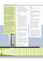
Mounting the new battery module<br />
34007776EN/AD - Page 20<br />
Carry out the above instructions in reverse order.<br />
◗ To ensure safety and high performance, use only batteries supplied by EATON.<br />
◗ Take care to firmly press together the two parts of the connector during remounting.<br />
5.3 Maintenance on a UPS equipped with the HotSwap MBP module<br />
HotSwap MBP<br />
49<br />
E<br />
D<br />
UPS ON -<br />
OK to switch<br />
7<br />
By-pass<br />
Normal<br />
BY PASS SWITCH<br />
50 51 52 53 54<br />
8<br />
9 10<br />
44<br />
55<br />
31<br />
56<br />
D - Remove the metal protection cover in<br />
front of the battery (two screws).<br />
E - Pull the plastic tab to remove the<br />
battery block and replace it.<br />
The HotSwap MBP module makes it<br />
possible to service or even replace the<br />
UPS without affecting the connected loads<br />
(HotSwap function).<br />
Maintenance:<br />
1 - Set switch (53) to the Bypass position.<br />
The red LED on the HotSwap MBP module<br />
goes ON, indicating that the load is<br />
supplied directly with AC input power.<br />
2 - Stop the UPS by pressing the ON/OFF<br />
button (27) on the UPS control panel. LED<br />
(51) "UPS ON - OK to switch" goes OFF, the<br />
UPS can now be disconnected and<br />
replaced.<br />
Return to normal operation:<br />
1 - Check that the UPS is correctly<br />
connected to the HotSwap MBP module.<br />
2 - Start the UPS by pressing the ON/OFF<br />
button (27) on the UPS control panel. LED<br />
(51) "UPS ON - OK to switch" on the<br />
HotSwap MBP module goes ON<br />
(otherwise, there is a connection error<br />
between the HotSwap MBP module and<br />
the UPS).<br />
3 - Set switch (53) to the Normal position.<br />
The red LED on the HotSwap MBP module<br />
goes OFF.
5.4 Training centre<br />
5. Maintenance<br />
To fully master operation of your EATON product and carry out level 1 servicing, see our complete range of technical<br />
training courses, available in both French and English.<br />
For further information, please visit our website: www.eaton.com<br />
34007776EN/AD - Page 21
6. Appendices<br />
6.1 Technical specifications<br />
34007776EN/AD - Page 22<br />
Output power <strong>2200</strong> VA (1) /<br />
1980 W<br />
Electrical supply network<br />
◗ Rated input voltage<br />
◗ Input voltage range<br />
◗ Frequency<br />
◗ <strong>Power</strong> factor<br />
◗ Leakage current<br />
Load output<br />
◗ Voltage<br />
◗ Frequency<br />
◗ Harmonic distortion<br />
◗ Overload capacity<br />
◗ Current<br />
<strong>EX</strong> <strong>2200</strong> <strong>EX</strong> 3000 <strong>EX</strong> 3000 XL <strong>EX</strong> <strong>EX</strong>B<br />
3000 VA (2) /<br />
2700 W (3)<br />
Single phase 230 V<br />
110 / 140 / 200 V to 284 V (4)<br />
50/60 Hz (autoselection)<br />
> 0.95<br />
< 2 mA<br />
3000 VA (2) /<br />
2700 W (3)<br />
Single phase 230 V ±3% (5)<br />
50/60 Hz ±0,5% (6)<br />
< 4% for linear load,<br />
< 6% for nonlinear load<br />
102% continuous, 105% 20s, > 130% 1.5s<br />
9.6 A (7)<br />
Battery 6 x 12V - 7 Ah,<br />
sealed lead acid,<br />
maintenance free<br />
Environment<br />
◗ Operating temperature range<br />
◗ Relative humidity<br />
◗ Storage temperature range<br />
◗ Altitude<br />
◗ Noise level<br />
6 x 12V - 9 Ah,<br />
sealed lead acid,<br />
maintenance free<br />
13 A (8)<br />
without internal<br />
battery<br />
0°C to 40°C<br />
20% to 90% (without condensation)<br />
-25°C to 40°C<br />
1000 m<br />
< 46 dBA < 50 dBA<br />
Two 6 x 12 V - 9 Ah<br />
strings, sealed<br />
lead acid,<br />
maintenance free<br />
(1) Depending on the output voltage selected: 200V / 208V / 220V / 230V / 240V, the output power is<br />
1980VA / 1980VA / <strong>2200</strong>VA / <strong>2200</strong>VA / <strong>2200</strong>VA.<br />
(2) Depending on the output voltage selected: 200V / 208V / 220V / 230V / 240V, the output power is<br />
2700VA / 2700VA / <strong>3000VA</strong> / <strong>3000VA</strong> / <strong>3000VA</strong>.<br />
(3) Standard output power is 2700 W, 2400 W with an <strong>EX</strong>B module.<br />
(4) Values for 33% / 66% / 100% of UPS output.<br />
(5) Programmable: 200V / 208V / 220V / 230V / 240V using the UPS Config software.<br />
(6) Frequency-converter mode is programmable using the UPS Config software.<br />
(7) Depending on the output voltage selected: 200V / 208V / 220V / 230V / 240V, the maximum output current is<br />
9.9A / 9.5A / 10A / 9.6A / 9.2A.<br />
(8) Depending on the output voltage selected: 200V / 208V / 220V / 230V / 240V, the output current is<br />
13.5A / 13A / 13.6A / 13A / 12.5A.
6.2 Glossary<br />
6. Appendices<br />
Bypass AC input Bypass line from the AC-power source, controlled by the UPS, used to directly supply the<br />
load if an overload or a malfunction occurs on the UPS.<br />
Backup time Time during which the load can be supplied by the UPS operating on battery power.<br />
Battery test Internal UPS test to check battery status.<br />
Cold start The devices connected to the UPS can be started even if AC input power is not available.<br />
The UPS operates on battery power alone.<br />
Deep discharge Battery discharge beyond the permissible limit, resulting in irreversible damage to the<br />
battery.<br />
FlexPDU Module with UPS outlets for installation in a bay. There are different modules with different<br />
types of outlets.<br />
Frequency converter Operating mode used to convert the AC-power frequency between the UPS input and<br />
output<br />
(50 Hz -> 60 Hz or 60 Hz -> 50 Hz).<br />
HotSwap MBP UPS manual-bypass module for maintenance. There are different modules with different<br />
types of outlets.<br />
Load Devices or equipment connected to the UPS output.<br />
Low-battery<br />
warning<br />
This is a battery-voltage level indicating that battery power is low and that the user must<br />
take action in light of the imminent break in the supply of power to the load.<br />
Normal AC input The AC-power line supplying the UPS under normal conditions.<br />
Percent load Ratio of the power effectively drawn by the load to the maximum output of the UPS.<br />
Personalisation It is possible to modify certain UPS parameters set in the factory. Certain UPS functions<br />
can also be modified by the Personal Solution-Pac software to better suit user needs.<br />
Programmable<br />
outlets<br />
These outlets can be automatically shut down during operation on battery power<br />
(shutdown time delays can be programmed with the Personal Solution Pac software). The<br />
UPS has two sets of two programmable outlets.<br />
UPS Uninterruptible <strong>Power</strong> <strong>System</strong>.<br />
UPS ON/OFF<br />
controlled by<br />
software<br />
This function enables or disables initiation of UPS ON/OFF control sequences by computer<br />
power management software.<br />
34007776EN/AD - Page 23
www.eaton.com<br />
34007776EN/AD