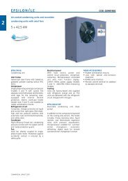
Manual_ERV-Wall Mount.pdf - Industrial Air
Manual_ERV-Wall Mount.pdf - Industrial Air
Manual_ERV-Wall Mount.pdf - Industrial Air

You also want an ePaper? Increase the reach of your titles
YUMPU automatically turns print PDFs into web optimized ePapers that Google loves.
4 Remove heat exchanger by removing security screws, and drawing forward towards<br />
yourself;<br />
5 Cut aperture 715mm wide x 760mm high. The depth of the carcass is 595mm with an<br />
additional 145 mm protruding face panel (see drawing);<br />
6 The unit must be inserted from inside the room. Push unit through aperture until flange<br />
seals against the wall;<br />
7 Fix through bottom and through sides 460mm up from bottom;<br />
8 Timber or metal sealing batons for the rear of the unit will need to be supplied by the<br />
installer;<br />
9 Replace fan drawer, heat exchanger and security screws, filter and front grille.<br />
2.3 Electrical<br />
• A power supply rated at 240v +/- 10% 1 phase, 50Hz is required to operate two<br />
80W fan motors within manufacturer's tolerances. They are controlled by a<br />
variable speed switch<br />
• Mains cables and control circuit wires are to be connected as per wiring diagram<br />
and all wiring must comply with relevant local wiring rules.<br />
• Single phase fan motors are internally protected and there is no need for<br />
external overload switches.<br />
WM-<strong>ERV</strong> <strong>Manual</strong> 2005.2.doc2<br />
6