Manual_ERV-Wall Mount.pdf - Industrial Air
Manual_ERV-Wall Mount.pdf - Industrial Air
Manual_ERV-Wall Mount.pdf - Industrial Air

You also want an ePaper? Increase the reach of your titles
YUMPU automatically turns print PDFs into web optimized ePapers that Google loves.
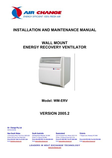
INSTALLATION AND MAINTENANCE MANUAL<br />
<strong>Air</strong> Change Pty Ltd<br />
ACN 003 508 996<br />
New South Wales<br />
12 Parraweena Road, Taren Point, NSW 2229<br />
PO Box 2403 Taren Point NSW 2229<br />
Phone (02) 9531 4699, Fax 02 9531 5294<br />
Email sales@air-change.com<br />
WALL MOUNT<br />
ENERGY RECOVERY VENTILATOR<br />
Model: WM-<strong>ERV</strong><br />
VERSION 2005.2<br />
South Australia<br />
239 Magill Road, Maylands, SA 5069<br />
PO Box 171 Stepney SA 5069<br />
Phone (08) 8366 6563, Fax (08) 8366 6501<br />
Email sales.sa@air-change.com<br />
Queensland<br />
Unit 2/10 Central Court, Hillcrest, QLD 4118<br />
PO Box 1175 Browns Plains QLD 4118<br />
Phone (07) 3809 3987, Fax (07) 3809 3989<br />
Email sales.qld@air-change.com<br />
LEADERS IN HEAT EXCHANGE TECHNOLOGY<br />
www.air-change.com<br />
Victoria<br />
1 Tangara Lane, Harkaway VIC 3806<br />
Phone (03) 8790 4500, Fax (03) 8790 4600<br />
Email sales.vic@air-change.com
1 INTRODUCTION .................................................................................................................. 3<br />
1.1 Safety Considerations ..................................................................................................... 3<br />
1.2 Note to Installer............................................................................................................... 3<br />
1.3 Inspection and Unpacking............................................................................................... 4<br />
1.4 Unit Handling.................................................................................................................. 4<br />
2 INSTALLATION OF WM-<strong>ERV</strong>............................................................................................ 5<br />
2.1 Location .......................................................................................................................... 5<br />
2.1.1 General ........................................................................................................................... 5<br />
2.1.2 Internal Inlet/Outlet Considerations........................................................................ 5<br />
2.1.3 External Inlet/Outlet Considerations....................................................................... 5<br />
2.2 Installation and fitting of Ventilation unit....................................................................... 5<br />
2.3 Electrical ......................................................................................................................... 6<br />
3 SYSTEM COMPONENTS..................................................................................................... 7<br />
3.1 General ............................................................................................................................ 7<br />
3.2 System Components........................................................................................................ 7<br />
3.2.1 Cabinet ........................................................................................................................... 7<br />
3.2.2 Fans ................................................................................................................................ 7<br />
3.2.3 Heat Exchanger .............................................................................................................. 7<br />
3.2.4 Filters ............................................................................................................................. 8<br />
3.2.5 Electrical ........................................................................................................................ 8<br />
3.3 Schematic Dimensional Data and Wiring Diagram - Following Pages.......................... 8<br />
4 S<strong>ERV</strong>ICE AND MAINTENANCE........................................................................................ 9<br />
4.1 Ventilation unit General.................................................................................................. 9<br />
4.2 Heat exchangers - <strong>Air</strong> Change Enthalpy Heat exchangers ........................................... 9<br />
5.1.1 Enthalpy Heat exchanger Maintenance.......................................................................... 9<br />
4.3 Fans ............................................................................................................................... 10<br />
4.4 Maintenance Schedule .................................................................................................. 10<br />
4.4.1 General ......................................................................................................................... 10<br />
4.4.2 Monthly Maintenance Schedules.......................................................................... 10<br />
4.4.3 Three-Monthly Checks ......................................................................................... 10<br />
4.4.4 Annual Maintenance .................................................................................................... 10<br />
WARRANTY INFORMATION, TERMS & CONDITIONS...................................................... 12<br />
WM-<strong>ERV</strong> <strong>Manual</strong> 2005.2.doc2<br />
2
AIR-CHANGE 100% OUTDOOR AIR WALL MOUNTED<br />
ENERGY RECOVERY VENTILATOR (WM-<strong>ERV</strong>)<br />
1 INTRODUCTION<br />
1.1 Safety Considerations<br />
IMPORTANT<br />
DO NOT LEAVE HEAT EXCHANGER EXPOSED TO DIRECT SUNLIGHT. Prolonged<br />
exposure to UV light can cause severe damage to the structure of the heat<br />
exchanger, and will void the warranty.<br />
WARNING<br />
Improper installation, service, maintenance or use can cause fire, electrical shock or<br />
other conditions which may cause personal injury or property damage and will void the<br />
warranty. Check with <strong>Air</strong> Change or nearest <strong>Air</strong> Change dealer for any information<br />
required on the ventilation unit equipment.<br />
DANGER<br />
Electrical shock can cause personal injury or death. Before performing any work<br />
on this equipment, the electrical supply must be turned off at the electrical<br />
service box to avoid the possibility of shock, injury or damage to equipment.<br />
Note: There may be more than one power supply circuit.<br />
1.2 Note to Installer<br />
• Only trained and qualified personnel should install, repair or service air<br />
conditioning equipment. Untrained supervised operatives can perform basic<br />
maintenance functions such as cleaning or replacing filters. Service personnel<br />
must perform all other operations.<br />
• Installing and servicing air conditioning equipment can be hazardous due to<br />
electrical and mechanical components.<br />
• When working on electrical equipment, observe precautions in all literature, tags<br />
and labels attached to or shipped with unit. Follow all safety codes and<br />
guidelines. Wear safety goggles, work gloves and any protective clothing.<br />
• All work must comply with relevant SAA wiring rules and local authority codes.<br />
Installers must ensure that all statutory regulations and by laws have been<br />
addressed.<br />
WM-<strong>ERV</strong> <strong>Manual</strong> 2005.2.doc2<br />
3
• Installers must ensure that the structures built to take the units have been<br />
suitably constructed for the purpose, all safety precautions have been applied<br />
prior to installation, and all preparation work has been constructed and suitably<br />
sized for its purpose.<br />
1.3 Inspection and Unpacking<br />
• The unit should be inspected upon delivery for possible external damage<br />
incurred during transport. If damage is evident it should be noted on the freight<br />
docket and the <strong>Air</strong>-change sales office contacted. A claim should be lodged with<br />
shipping company within three (3) days if shipment is damaged or incomplete.<br />
• If major damage is apparent, do not lift unit on to site without prior approval from<br />
<strong>Air</strong>-change. The unit was inspected prior to packing and was in perfect condition<br />
at that time.<br />
• Test load to see if the weight is equally distributed. Do this by lifting the unit a few<br />
centimetres off the floor and holding it there before lifting any further or before<br />
transporting the unit.<br />
• Check unit rating plate to ensure the correct unit matches the job specifications.<br />
1.4 Unit Handling<br />
• Protective packaging should not be removed until the unit is at the point of<br />
installation. When removing packaging, be careful not to damage, scratch or dent<br />
the unit. After removal of packaging or crating, all removable access panels<br />
should be opened to inspect for unit internal damage.<br />
• Exercise extreme caution when lifting.<br />
WM-<strong>ERV</strong> <strong>Manual</strong> 2005.2.doc2<br />
4
2 INSTALLATION OF WM-<strong>ERV</strong><br />
2.1 Location<br />
2.1.1 General<br />
• The ventilation unit is located through an outside wall or suitable window<br />
• The WM-<strong>ERV</strong> package is marked with stickers “Fresh air” “Supply <strong>Air</strong>”,<br />
“Return <strong>Air</strong>” and “Exhaust <strong>Air</strong>” showing the air path through the unit.<br />
2.1.2 Internal Inlet/Outlet Considerations<br />
• Whenever possible, the unit should be located where the fresh air can be<br />
mixed with the refrigerated air from the air conditioner.<br />
• The prime function of the unit is to deliver pre-conditioned fresh air by<br />
transferring the energy from the cold stale return air. Therefore the unit must<br />
be located away from where the cold return air can be affected by a heat<br />
source i.e. a frequently opening door to exterior, or near any major source of<br />
heat generation.<br />
• The introduced fresh air should also be above head height to avoid blowing directly<br />
on to occupants.<br />
2.1.3 External Inlet/Outlet Considerations<br />
• The exhaust discharge should be directed in a clear path away from any<br />
windows that can be opened.<br />
• Location of the fresh air inlets should adhere to the Australian Standards<br />
1668.2 Code.<br />
• The fresh air intake should be positioned clear of any objects which could<br />
obstruct the airflow and be clear of any polluted air from other units, exhaust<br />
fans, kitchen or toilet exhausts, etc.<br />
• When the unit is fully installed, make sure the outside inlet grille opening and the<br />
return air inside are completely free and not blocked off in any way.<br />
2.2 Installation and fitting of Ventilation unit<br />
NOTE: Any studs that are cut have to be cross noggined for support of the wall.<br />
Steps:<br />
1 Remove front panel by lifting up and out;<br />
2 Remove fan drawer by drawing forward towards yourself;<br />
3 Remove filter by drawing forward towards yourself;<br />
WM-<strong>ERV</strong> <strong>Manual</strong> 2005.2.doc2<br />
5
4 Remove heat exchanger by removing security screws, and drawing forward towards<br />
yourself;<br />
5 Cut aperture 715mm wide x 760mm high. The depth of the carcass is 595mm with an<br />
additional 145 mm protruding face panel (see drawing);<br />
6 The unit must be inserted from inside the room. Push unit through aperture until flange<br />
seals against the wall;<br />
7 Fix through bottom and through sides 460mm up from bottom;<br />
8 Timber or metal sealing batons for the rear of the unit will need to be supplied by the<br />
installer;<br />
9 Replace fan drawer, heat exchanger and security screws, filter and front grille.<br />
2.3 Electrical<br />
• A power supply rated at 240v +/- 10% 1 phase, 50Hz is required to operate two<br />
80W fan motors within manufacturer's tolerances. They are controlled by a<br />
variable speed switch<br />
• Mains cables and control circuit wires are to be connected as per wiring diagram<br />
and all wiring must comply with relevant local wiring rules.<br />
• Single phase fan motors are internally protected and there is no need for<br />
external overload switches.<br />
WM-<strong>ERV</strong> <strong>Manual</strong> 2005.2.doc2<br />
6
3 SYSTEM COMPONENTS<br />
3.1 General<br />
• The <strong>Air</strong> Change <strong>Wall</strong> <strong>Mount</strong>ed Energy Recovery Ventilator (WM-<strong>ERV</strong>) has been<br />
developed for Classrooms and other applications to supply fresh air to meet<br />
Ventilation codes. The system pre-cools or pre-heats and dehumidifies outdoor<br />
air by transferring the energy from the return air through the heat exchanger<br />
walls to the incoming outdoor air. The Enthalpy Heat Exchanger inbuilt in the<br />
Ventilator has been designed to return around 75% efficiency.<br />
• The WM-<strong>ERV</strong> is professionally assembled, internally wired through out, with easy<br />
access for filter change. The Front grille is designed to be removed by lifting<br />
upwards and then pulling towards you, allowing access to filters. Remember to<br />
always turn the power off before removing the front grille.<br />
• The WM-<strong>ERV</strong> provides 300 l/s outdoor air on low speed and 350 l/s outdoor air<br />
on high speed.<br />
3.2 System Components<br />
3.2.1 Cabinet<br />
• Prefabricated wall and ceiling panels of are constructed of 1.2mm galvanised<br />
sheet metal, bonded to 10mm aluminium polyethylene insulation.<br />
3.2.2 Fans<br />
• Supply and exhaust fans are 80W centrifugal direct drive and are constructed<br />
using forward curved vanes fabricated from galvanised steel.<br />
• Fans are controlled by an HPM electronic speed control.<br />
3.2.3 Heat Exchanger<br />
• The Energy Reclaim (enthalpy) heat exchanger uses a combination of cross<br />
flow and counter flow, with enthalpy transfer media between moulded plastic<br />
air guiding frames for a very high efficiency and long life. The heat exchanger<br />
has been secured under pressure by galvanised steel end plates and corner<br />
fittings.<br />
• There is no cross contamination between the air paths.<br />
• The counter flow enthalpy heat exchanger incorporated into the unit will<br />
reclaim up to 75% of the energy (under normal operating conditions) from the<br />
return air and transfer it to the incoming outside air, i.e. to pre-treat the<br />
outside air. This results in a saving of up to 75% on the cost of heating or<br />
cooling the outdoor air. (Typical <strong>ERV</strong> use with normal air conditioning, see<br />
Plan and Side View schematic).<br />
WM-<strong>ERV</strong> <strong>Manual</strong> 2005.2.doc2<br />
7
• Heat exchanger is secured in place by two screws that secure the heat<br />
exchanger to the cabinet. This ensures that the heat exchanger can only be<br />
removed from inside the room.<br />
3.2.4 Filters<br />
• Filters are supplied and fitted in the factory. A single filter is inserted and<br />
removed via the return air inlet grid and provides filtering for both fresh air<br />
inlet and return air inlet of the heat exchanger.<br />
IMPORTANT: Never operate unit without filters fitted to the return<br />
and fresh air intakes.<br />
IMPORTANT: If these units are being used during construction when<br />
adhesive, sealers, ducts, new and used carpets are being installed make<br />
sure all equipment is fitted and adequately protected. We recommend<br />
using disposable or temporary filters during commissioning and during<br />
pre-hand over running.<br />
3.2.5 Electrical<br />
• Internal controls are all 240V supply. Wiring is done in accordance to<br />
Australian Standards and specific state electrical authorities.<br />
• Single phase fan motors are internally protected and there is no need for<br />
external overloads in the ventilation unit.<br />
3.3 Schematic Dimensional Data and Wiring Diagram - Following<br />
Pages.<br />
WM-<strong>ERV</strong> <strong>Manual</strong> 2005.2.doc2<br />
8
4 S<strong>ERV</strong>ICE AND MAINTENANCE<br />
4.1 Ventilation unit General<br />
• Ventilation units have been designed for easy maintenance with first quality materials<br />
and components used throughout. Preventative maintenance programs will vary<br />
according to actual working conditions and locations and hours of usage by the client.<br />
<strong>Air</strong> Change will be pleased to provide advice on special service requirements for<br />
particular installations.<br />
4.2 Heat exchangers - <strong>Air</strong> Change Enthalpy Heat exchangers<br />
IMPORTANT: Return and Fresh air filters must be changed/cleaned<br />
regularly to ensure airflow is unrestricted. Heat exchanger warranty may be<br />
voided if filters are not cleaned according to maintenance schedule and if<br />
proper filtration standards are not adhered to.<br />
NOTE: <strong>Air</strong> Change can provide a heat exchanger replacement service on<br />
request.<br />
WARNING: Switch off unit before attempting to remove parts for<br />
cleaning.<br />
5.1.1 Enthalpy Heat exchanger Maintenance<br />
WM-<strong>ERV</strong> <strong>Manual</strong> 2005.2.doc2<br />
IMPORTANT: DO NOT WASH THE ENTHALPY HEAT EXCHANGER<br />
• The Enthalpy Heat exchanger has a brown paper-based enthalpy exchange<br />
media between the plates which can be vacuumed or brushed gently.<br />
IMPORTANT: DO NOT ATTEMPT TO CHANGE THE LENGTH OF THE<br />
HEAT EXCHANGER BY REMOVING END PLATES AND PLASTIC PLATES.<br />
This can mean that the media between the plates is dislodged from its<br />
position and therefore will cause lack of performance through increased<br />
pressure drop through the heat exchanger or damage to the Sensible<br />
media. Any tampering with the heat exchanger may invalidate our warranty<br />
and <strong>Air</strong>-Change will not be held responsible for lack of performance or<br />
pressure drop.<br />
If the heat exchanger is the incorrect length, please return to <strong>Air</strong>-change for<br />
a replacement unit.<br />
9
4.3 Fans<br />
Fan shaft and motor bearings are of permanently lubricated, sealed type and require no<br />
regular maintenance other than a check on their general condition.<br />
4.4 Maintenance Schedule<br />
4.4.1 General<br />
• <strong>Air</strong>-change systems are designed for easy maintenance, with highest quality<br />
materials and components used throughout.<br />
• Preventative maintenance programs will vary according to actual working<br />
conditions and location and hours of usage by the client.<br />
• <strong>Air</strong>-change will be pleased to provide expert advice on special service<br />
requirements for particular installations.<br />
IMPORTANT: Failure to carry out regular maintenance may render<br />
warranty claims invalid if faults have been caused by lack of proper<br />
maintenance. <strong>Air</strong>-change may request to see the maintenance schedule<br />
carried out.<br />
4.4.2 Monthly Maintenance Schedules.<br />
• Filters should be inspected frequently immediately after installation to confirm<br />
the frequency of cleaning needed for the particular location. Regular<br />
change/clean of filters is necessary to ensure normal operating conditions.<br />
• Vacuum or wash filters, and dry thoroughly before replacing.<br />
The following is a guide until frequency according to usage is established.<br />
4.4.3 Three-Monthly Checks<br />
• Repeat the Monthly Schedule<br />
• Clean Heat Exchanger (see section 4.1)<br />
• Check fan blower wheels for dirt build-up and tightness on shaft<br />
• Check all cabinet panels for correct fitting, alignment and seals, and clean<br />
cabinet as required. Ensure no insulation has been detached from panels.<br />
• All electrical terminals should be checked for tension on each maintenance<br />
visit with main switch off.<br />
4.4.4 Annual Maintenance<br />
• Repeat monthly and three-monthly checks<br />
WM-<strong>ERV</strong> <strong>Manual</strong> 2005.2.doc2<br />
10
• Check cabinet for any paint chips or abrasions and treat accordingly.<br />
• Measure and record the amperage of each motor against nameplate details.<br />
WM-<strong>ERV</strong> <strong>Manual</strong> 2005.2.doc2<br />
11
WARRANTY INFORMATION, TERMS & CONDITIONS<br />
Failure to carry out regular maintenance with a licensed and reputable<br />
refrigeration company may render warranty claims invalid if faults have been<br />
caused by lack of Maintenance. <strong>Air</strong>-change may request to see the<br />
maintenance schedule carried out.<br />
Management will need to keep records provided by service companies, which will<br />
detail the service done to each unit. This record is a summary of your service<br />
documentation for easy reference for management in case of a warranty claim.<br />
Your equipment is a major investment and will last for many years if properly<br />
maintained and serviced.<br />
<strong>Air</strong> Change Pty Ltd will only accept a completed warranty card [issued in each manual]<br />
or a copy of the original invoice complete with matching serial numbers as proof of<br />
purchase. This information must be verified before the authorisation of any warranty<br />
claims. We also require details of servicing with all warranty claims.<br />
WM-<strong>ERV</strong> <strong>Manual</strong> 2005.2.doc2<br />
12