EPSILON-CF IOM.pdf - Industrial Air
EPSILON-CF IOM.pdf - Industrial Air
EPSILON-CF IOM.pdf - Industrial Air

You also want an ePaper? Increase the reach of your titles
YUMPU automatically turns print PDFs into web optimized ePapers that Google loves.
<strong>EPSILON</strong> <strong>CF</strong><br />
4.6 ÷ 39 kW<br />
Installation,<br />
operating<br />
and maintenance<br />
manual<br />
Manual 201482A02<br />
Issue 08.06<br />
Replaces --.--<br />
1370<br />
Packaged <strong>Air</strong>/water units Centrifugal fans
CONTENTS<br />
1. FIELD OF APPLICATION 2<br />
1.1 INTRODUCTION 2<br />
2. INSPECTION, TRANSPORT, SITE HANDLING 2<br />
2.1 INSPECTION 2<br />
2.2 UNPACKING 2<br />
2.3 LIFTING AND SITE HANDLING 3<br />
3. NON APPLICABLE APPLICATIONS 4<br />
4. SAFETY PRECAUTIONS 4<br />
4.1 DEFINITION OF DANGEROUS ZONE 4<br />
4.2 SAFETY RULES 5<br />
REFRIGERANT SAFETY DATA - R407C 6<br />
4.3 INSTALLATION IN AREAS SUBJECT TO THE RISK OF EXPLOSION 8<br />
4.4 PROTECTION 8<br />
4.5 LIGHTING 8<br />
4.6 QUALIFICATION OF PERSONNEL - OBLIGATIONS 8<br />
4.7 VARIOUS INSTRUCTIONS 8<br />
5. POSITIONING 9<br />
5.1 INDOOR UNIT POSITIONING 10<br />
6. INSTALLATION 11<br />
6.1 INSTALLATION CLEARANCES 11<br />
6.2 VIBRATION DAMPER MOUNTS (OPTIONAL) 11<br />
6.3 WATER PIPING CONNECTIONS 11<br />
RECOMMENDED HYDRAULIC CIRCUIT DIAGRAM FOR <strong>EPSILON</strong> <strong>CF</strong> 11<br />
RECOMMENDED HYDRAULIC CIRCUIT DIAGRAM FOR <strong>EPSILON</strong> <strong>CF</strong> /ST 1PS 12<br />
HYDRAULIC CIRCUIT DIAGRAM ST 12<br />
6.4 EVAPORATOR WATER PIPE CONNECTIONS 13<br />
6.5 WATER FLOW SWITCH INSTALLATION INSTRUCTIONS 14<br />
6.6 PRESSURE RELIEF VALVES 15<br />
6.7 INDOOR UNIT INSTALLATION 15<br />
6.8 INDOOR UNIT DUCTING 16<br />
6.9 FRESH AIR INTAKE 16<br />
6.10 FILTERS REMOVING AND CLEANING 17<br />
6.11 CONDENSATION WATER DISCHARGE 17<br />
6.12 CONNECTIONS FOR VERSION /LE (MOTOCONDENSING UNIT) 18<br />
6.12.1 Procedures to follow when sizing refrigerant lines 19<br />
6.12.2 Evaporating section at lower level than condensing section 19<br />
6.12.3 Evaporating section positioned higher than the condensing unit section 19<br />
TABLE 1 - EXTERNAL PIPE DIAMETERS FOR /LE VERSION 20<br />
6.13 WATER FLOW RATE TO EVAPORATOR 20<br />
6.14 WATER TEMPERATURE AT THE EVAPORATOR 20<br />
6.15 AMBIENT AIR TEMPERATURE 21<br />
6.16 OPERATION IN LOW AMBIENT AIR TEMPERATURE CONDITIONS (OPTION) 21<br />
6.17 OPERATION WITH LOW TEMPERATURE CHILLED WATER AT EVAPORATOR 21<br />
TABLE 2 - FREEZING POINT FOR WATER-ANTIFREEZE MIXTURES 21<br />
6.18 ELECTRICAL CONNECTIONS 22<br />
6.18.1 Introduction 22<br />
6.18.2 Power supply to crankcase heaters 22<br />
6.18.3 Potential free contacts 22<br />
6.18.4 Circulating pump electrical connections 23<br />
6.18.5 Electric connection of the thermostat (optional) 23<br />
6.19 MICROPROCESSOR CONTROLLER 23<br />
<strong>Air</strong> Blue
7. START-UP 24<br />
7.1 PRELIMINARY CHECKS 24<br />
8. STARTING THE UNIT 25<br />
8.1 SEASONAL STOP 25<br />
8.2 EMERGENCY STOP 25<br />
9. CHECKS DURING OPERATION 26<br />
9.1 CHECKING THE REFRIGERANT CHARGE 26<br />
10. CALIBRATION OF CONTROL EQUIPMENT 26<br />
10.1 INTRODUCTION 26<br />
TABLE 3 - CALIBRATION OF SAFETY DEVICES 26<br />
11. MAINTENANCE AND PERIODIC CHECKS 27<br />
11.1 WARNINGS 27<br />
11.2 INTRODUCTION 27<br />
11.3 ENVIRONMENTAL CONSIDERATIONS 28<br />
12. DECOMMISSIONING THE UNIT 28<br />
REFRIGERANT CIRCUIT<br />
TECHNICAL CATALOGUE<br />
ENCLOSURES<br />
WIRING DIAGRAM<br />
MICROPROCESSOR CONTROLLER<br />
<strong>Air</strong> Blue<br />
29<br />
33
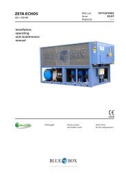
<strong>EPSILON</strong> <strong>CF</strong> - Water chiller<br />
The <strong>EPSILON</strong> <strong>CF</strong> series of air cooled chillers and heat pumps, are available in various sizes with capacities from<br />
4.6 to 39 kW.<br />
For construction characteristics, models available and technical data, refer to the Technical Booklet.<br />
PRODUCT DESIGNATION<br />
MODEL<br />
unit type /version /option hydraulic modul SIZE<br />
<strong>EPSILON</strong> <strong>CF</strong> 5<br />
/HP /ST 1P 7<br />
/LE /ST 1PS 8.5<br />
/LE/HP /ST S 10<br />
12.5<br />
15<br />
20<br />
25<br />
30<br />
35<br />
Meaning of values<br />
Tipo refrigerante<br />
Refrigerant type<br />
Kältemitteltyp<br />
Type rèfrigèrant<br />
Numero circuiti refrigerante<br />
Refrigerant circuit number<br />
Anzahl der Kältekreise<br />
Nombre circuits réfrigérant Product designation example: <strong>EPSILON</strong> <strong>CF</strong> /LE 25<br />
Number to identify the indicative<br />
cooling capacity (in this case 25 kW)<br />
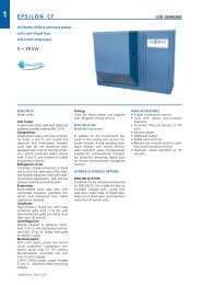
The model, serial number, characteristics, power supply, etc. are shown by means of decals on the unit.<br />
Modello/Model<br />
Modell/Modèle<br />
Corrente massima assorbita<br />
Max. absorbed current<br />
Max.Stromaunfnahme<br />
Courant maxi absorbée<br />
Tensione-Fasi-Frequenza<br />
Voltage-Phases-Frequency<br />
Spannung-Phasen-Frequenz<br />
Tension-Phases-Fréquence<br />
IP quadro elettrico<br />
IP electrical panel<br />
IP Schaltschrank<br />
IP tableau électrique<br />
Matricola<br />
Serial number<br />
Seriennumer<br />
Matricule<br />
Corrente massima di spunto<br />
Max starting current<br />
Max. Anlaufstrom<br />
Courant maxi de démarrage<br />
A A<br />
Tensione circuiti ausiliari<br />
Auxiliary circuit voltage<br />
Steuerspannung<br />
Tension circuits auxiliares<br />
Press. massima circuito idraulico Data di produzione<br />
Max. hydraulic circuit pressure Date of manufacture<br />
Max. zulässigerDruck<br />
im Wassersystem Herstellungstatum<br />
Press. Maxi circuit hydraulique Date de production<br />
kPa<br />
bar<br />
Press. max refriger. alta/bassa<br />
Max. Refrig. pressure high/low<br />
Max. N/n Kaltemrttelbetriebsaruck<br />
Pression maxi refrig. haute/basse<br />
Carica refrigerante per circuito(kg)/Refrigerant charge per circuit(kg)<br />
Kältemittel Füllmenge je Kreislauf (kg)/ Charge r éfrigérant par circuit(kg)<br />
C1 C2<br />
C3 C4<br />
kPa<br />
bar<br />
25<br />
MODELLO - MODELE - MODEL - TYP<br />
MATRICOLA - MATRICULE - SERIAL NO. - SERIENUMMER<br />
REFRIGERANTE - REFRIGERANT - KÄLTEMITTEL - REFRIGERANT<br />
<strong>Air</strong> Blue • 1
1. FIELD OF APPLICATION<br />
The equipment is designed for cooling (chiller only versions) or cooling/heating (heat pump versions) water,<br />
which is usually applied to air conditioning or refrigeration systems. Use is recommended within the limits as<br />
specified in the Technical Booklet.<br />
1.1 INTRODUCTION<br />
– When installing or servicing the unit, it is necessary to strictly follow the rules described in this manual, to<br />
conform to all the items detailed on the unit labels and take any necessary precaution.<br />
– Pressure in refrigerant circuits and danger from electrical shock can be hazardous when installing or servicing<br />
the unit.<br />
2. INSPECTION, TRANSPORT, SITE HANDLING<br />
2.1 INSPECTION<br />
After receiving the unit, immediately check its integrity. The unit will have left the factory in perfect condition<br />
therefore on receiving the unit any damage must be verbally described to the carrier and recorded on the Delivery<br />
Note which must be signed by both parties. Blue Box or their Agent must be informed, as soon as possible, of<br />
the extent of the damage.<br />
The Customer should prepare a written statement and photographic evidence regarding any severe damage.<br />
2.2 UNPACKING<br />
Any work on the unit must be carried out only by trained personnel.<br />
Attention: before repairing or servicing the unit, ensure that the<br />
electrical supply is disconnected.<br />
Unpack the unit with care so as not to damage the unit. Disposal of packing materials is the responsibility of<br />
the receiver and must be made in accordance with local and national regulations.<br />
Caution: ensure that the method of lifting does not allow the unit<br />
to slip from chains and slings or turn-over or slide from lifting<br />
devices.<br />
<strong>Air</strong> Blue • 2
2.3 LIFTING AND SITE HANDLING<br />
Avoid sudden movements and jolts when unloading and positioning the unit. Internal handling procedures must<br />
be conducted with care. Do not exert leverage on the components of the machine. The unit must be lifted by<br />
inserting steel tubes through the lifting attachments shown by the relative labels (yellow arrow).<br />
The unit must be lifted by harnessing it as shown in figure 1: use ropes or straps of sufficient length and spacer<br />
bars to avoid damage to the unit’s side panels and cover.<br />
Alternatively, the unit can be lifted by a forklift truck, inserting the forks under the pallet (see figure 1).<br />
Figure 1<br />
All lifting devices, ropes and sling etc, must be selected by someone<br />
with the required knowledge and be fully responsible for the use<br />
thereof.<br />
The unit must be properly balanced and when using a forklift the<br />
forks should be in a low position.<br />
If the unit is not balanced apply ballast. Any protruding parts should<br />
not be supported by hand.<br />
Do not walk or stand beneath or in the proximity of the load.<br />
Transportation must be by specialised personnel (truck operators,<br />
hook-up personal), equipped with the necessary protection equipment<br />
(overalls, safety shoes, protective gloves, helmets, goggles).<br />
The manufacturer will not accept any responsibility in case of possible<br />
accidents due to the non-observance of these warnings.<br />
<strong>Air</strong> Blue • 3
3. NON APPLICABLE APPLICATIONS<br />
The unit should not be applied in the following circumstances:<br />
– in an explosive atmosphere;<br />
– in an inflammable atmosphere;<br />
– in excessively dusty environments;<br />
– by untrained personnel;<br />
– in any manner contrary to the rules in force.<br />
– with incorrect installation;<br />
– with defective power supply;<br />
– without total or partial observance of instructions;<br />
– with lack of maintenance and/or use of non original spare parts;<br />
– with modifications or other changes unauthorized by the manufacturer;<br />
– within a location that is not clear of debris or other objects;<br />
– within a location that is inadequately cleared;<br />
– with anomalous vibrations in the location area.<br />
4. SAFETY PRECAUTIONS<br />
The unit has been designed in accordance with to the followings directives:<br />
DIRECTIVES<br />
98/37 CEE Units safety<br />
89/336 CEE Electromagnetic compatibility<br />
73/23 CEE Low tension<br />
97/23 CEE Devices under pressure<br />
RULES<br />
– EN 60204-1: Machinery safety - electric equipment of units<br />
12/1997 - Part 1: General rules<br />
– EN 50081-2: Electromagnetic compatibility general rules on emission.<br />
08/1993 - Part 2: <strong>Industrial</strong> environment<br />
– EN 50082-2: Electromagnetic compatibility general rules on immunity<br />
03/1995 - Part 2: <strong>Industrial</strong> environment<br />
– EN 292/2: Safety of machinery. General rules of design<br />
09/1991 - Part 2 a: Specifications and technical principles.<br />
– EN 294: Safety of machinery - Safety distance to avoid contact with upper limbs.<br />
06/1992<br />
– EN 349: Minimum distance to avoid crushing of parts of human body. .<br />
04/1993<br />
– EN 378-2: Devices under pressure Refrigeration plants and heat pumps:<br />
01/2001 Safety and environmental requirements.<br />
- Part 2: Design, manufacture, test, installation, marking and documentation<br />
4.1 DEFINITION OF DANGEROUS ZONE<br />
Only authorised operators must be allowed in the vicinity of the unit.<br />
– The external danger zone concerns a space of approximately 2 m in width around the perimeter of the<br />
machine. Access to this area must be prevented by suitable guarding in the event that the unit is located in<br />
an unprotected area that is easily accessible to unauthorised persons.<br />
– The interior of the unit is designated as a danger zone. Any access to this zone must be by qualified personnel<br />
only after all electrical power has been de-energised.<br />
<strong>Air</strong> Blue • 4
4.2 SAFETY RULES<br />
The unit is designed and built in accordance with the PED 97/23CE rules, to ensure the maximum level of safety.<br />
To avoid possible situations of risk adhere to the following rules at all times:<br />
– All work on the unit must be performed by qualified personnel. Before working on the unit, ensure that the<br />
designated personnel are conversant with the documentation supplied.<br />
– Always ensure there is a copy of the documentation in the immediate vicinity of the unit.<br />
– The operations indicated in this manual must be integrated with the procedures of instruction manuals of<br />
other systems or devices assembled in the unit. The manuals contain all the necessary information to manage,<br />
in safety, all devices and the possible operating modes.<br />
– Use the appropriate personal safety equipment (gloves, helmet, safety goggles, safety footwear, etc.) for all<br />
maintenance and control operations on the unit.<br />
– Avoid loose garments, dangling accessories such as ties, chains, watches which could be entangled in moving<br />
parts of the unit.<br />
– Use only tools and equipment that are in good working order.<br />
– The compressor compartment contains various high temperature components. Adopt the maximum caution<br />
when working in the vicinity of the compressors and avoid touching any parts of the unit without appropriate<br />
protection.<br />
– Do not work within the theoretical discharge trajectory of the relief valves.<br />
– If units are located in unprotected positions easily accessible by unqualified personnel, suitable protection<br />
grilles must be installed.<br />
– The user must consult the installation and operating section of this manual regarding the systems incorporated.<br />
– All units have safety / warning labels. It is forbidden to remove any safety /warning label.<br />
It is forbidden to:<br />
– Remove or by-pass any safety measure for people protection.<br />
– Tamper and/or modify, even partially, the safety devices of the unit.<br />
– In case of alarm signals, and the consequent intervention of safety devices, the operator must contact qualified<br />
maintenance technicians. A possible accident could cause serious injuries or death.<br />
– All safety devices must be verified according to the instruction manual. Verification and repair/adjustment<br />
must be performed by qualified personnel authorised with a written instruction by the customer. A copy of<br />
the results of the repair/adjustment made must be left on the unit. In case of alarm signals, and the consequent<br />
intervention of safety devices, the operator must contact qualified maintenance technicians. A possible<br />
accident could cause serious injuries or death.<br />
The Manufacturer is not responsible for any damage to people, pets or objects due to the re use of any part of<br />
the unit for functions or assemblies different to its original purpose.<br />
It is forbidden to tamper/change without authorisation any component of the unit.<br />
The use of accessories, tools or components different from those recommended by the Manufacturer exonerates<br />
the Manufacturer from any civil or penal responsibility.<br />
The operations of removal and demolition of the unit must be carried out only by personnel adequately trained<br />
and equipped.<br />
<strong>Air</strong> Blue • 5
REFRIGERANT SAFETY DATA - R407C<br />
1. IDENTIFICATION<br />
OF THE SUBSTANCE<br />
2. COMPOSITION /<br />
INFORMATION ON<br />
INGREDIENTS<br />
3. HAZARDS<br />
IDENTIFICATION<br />
1.1 Identification of the<br />
preparation:<br />
R407C<br />
Synonyms: HFC-32lHFC-125IHFG134a<br />
Formula: Mixture<br />
EE-No: difluoromethane (HFC-32) : 200-839-4<br />
1-1-1-2-tetrafluoroethane UHFC-134a): 212-377-0<br />
pentafluoroethane (HFC-125) : 206-557-8<br />
Chemical Name CAS-No – Wt % – Symbol/s: & phases “R”<br />
difluoromethane 75/10/5 – 23 – F+;R12<br />
1-2-2-2-tetrafluoroethane 811/97/2 – 52<br />
pentafluoroethane 354/33/ 6 – 25<br />
3.1 Most important hazards: Liquefied gas: may cause frostbite. Contact with eyes<br />
may cause irritation.<br />
4. FIRST-AID MEASURES 4.1 Eyes Rinse immediately with plenty of water for at least 15<br />
minutes.<br />
Keep eye wide open while rinsing. If symptoms persist,<br />
call a physician.<br />
Skin Liquefied gas may cause frostbite. Wash frostbitten<br />
areas with plenty of water. Do not remove clothing.<br />
Wash off with warm water. If skin irritation persists,<br />
call a physician.<br />
Inhalation Inhalation Move to fresh air in case of accidental<br />
inhalation of vapours. Oxygen or artificial respiration<br />
if needed. Do not apply artificial respiration if patient<br />
is breathing; Consult a physician after significant<br />
exposure. Do not give adrenaline or similar drugs.<br />
Ingestion Do not induce vomiting without medical advice. Call<br />
a physician immediately. Do not give drugs from<br />
adrenaline-ephedrine group.<br />
General advice Consult a physician alter significant exposure.<br />
5. FIRE-FIGHTING<br />
MEASURES<br />
6. ACCIDENTAL<br />
RELEASE MEASURES<br />
5.1 Suitable extinguishing<br />
media:<br />
5.2 Extinguishing media<br />
which must not be<br />
used for safety reasons:<br />
<strong>Air</strong> Blue • 6<br />
The product itself does not burn. Extinguish with<br />
carbon dioxide, dry chemical, foam or water spray.<br />
Use extinguishing measures that are appropriate to<br />
the environment.<br />
None<br />
5.3 Specific hazards: Possibility of generating hazardous reactions during a<br />
fire due to the presence of F and/or Cl groups. Fire or<br />
intense heat may cause violent rupture of packages.<br />
5.4 Special protective<br />
equipment for firefighters:<br />
In case of fire, west a self contained breathing<br />
apparatus. Protective suit.<br />
5.5 Specific methods: Standard procedure for chemical fires. In the event of<br />
fire, cool tanks with water spray.<br />
6.1 Personal precautions: Use personal protective equipment. Evacuate<br />
personnel to safe areas. Do not breath vapours or<br />
spray mist. Ensure adequate ventilation.<br />
6.2 Methods for cleaning up: Shut off leaks it without risk. Solid evaporates. Ensure<br />
adequate ventilation.
REFRIGERANT SAFETY DATA - R407C<br />
7. HANDLING<br />
AND STORAGE<br />
8. EXPOSURE<br />
CONTROLS /<br />
PERSONAL<br />
PROTECTION:<br />
9. STABILITY AND<br />
REACTIVITY<br />
10. TOXICOLOGICAL<br />
INFORMATION<br />
11. DISPOSAL<br />
CONSIDERATIONS<br />
12. TRANSPORT<br />
INFORMATION<br />
7.1 Handling: Keep away from heat, sources of ignition. Do not<br />
puncture or drop container, Provide sufficient air<br />
exchange and / or exhaust in work rooms.<br />
7.2 Storage: Keep containers tightly closed in a cool,<br />
well-ventilated place.<br />
Store in a cool and shaded area. Do not expose to<br />
temperatures above 50 °C. Keep tightly closed.<br />
8.1 Engineering measures to<br />
reduce exposure:<br />
<strong>Air</strong> Blue • 7<br />
Ensure adequate ventilation, especially in confined<br />
areas.<br />
8.2 Personal protection<br />
equipment:<br />
Respiratory protection: In case of insufficient ventilation wear suitable<br />
respiratory equipment, preferably a compressed<br />
airline breathing apparatus.<br />
Hand protection: Impervious butyl rubber gloves.<br />
Eye protection: Wear as appropriate: safety glasses, gaggles, Wear<br />
face-shield<br />
Skin and body<br />
protection:<br />
Wear as appropriate: safety glasses, gaggles.<br />
Wear face-shield and protective suit for abnormal<br />
processing problems.<br />
8.3 Exposure limit(s): 1-1-1-2-tetrafluoroethane 1000 ppm (TWA);<br />
difluoromethane: 1000 ppm (TWA);<br />
pentafluoroethane: 1000 ppm (TWA)(AIHA);<br />
9.1 Stability: Stable at normal conditions. No decomposition<br />
if stored and applied as directed. Decomposition<br />
starting from 250°C.<br />
9.2 Conditions to avoid: Do not expose to temperatures above 50 °C. Fire or<br />
Intense heat may cause violent rupture of packages.<br />
9.3 Materials to avoid: alkaline metals (Na, K), alkaline earth metals (Ca,<br />
Mg), finely divided aluminium, zinc.<br />
9.4 Hazardous decomposition<br />
products:<br />
halogenated compounds, hydrogen halides (HF, HCI),<br />
carbonyl halides (COCl2), carbon monoxide, carbon<br />
dioxide (C02).<br />
10.1 10.1 Acute toxicity:: LC50/inh./4 h/rat: > 500000 ppm<br />
10.2 Irritation<br />
Skin Slightly irritant, may cause frostbite.<br />
Eyes: Slightly irritant.<br />
10.4 Chronic toxicity: Chronic inhalation, no-observed-effect level (NOEL):><br />
10000 ppm rat.<br />
11.1 Waste from residues /<br />
unused products:<br />
Contaminated<br />
packaging:<br />
Offer surplus and non-recyclable solutions to an<br />
established disposal company. In accordance with<br />
local and national regulations. Refer to manufacturer/<br />
supplier for information on recovery/recycling.<br />
Do not reuse empty containers. Empty pressure<br />
vessels should be returned to supplier.<br />
No. O.N.U. 3340<br />
ADR/RID UN 3340 Refrigerant gas R407C, 2, 2° A, ADR/RID<br />
Label: 2
4.3 INSTALLATION IN AREAS SUBJECT TO THE RISK OF EXPLOSION<br />
The machines are not designed for operation within the field of application as specified in the directive ATEX<br />
94/9/EC – Pres. Decree 23/3/98 no. 126.<br />
4.4 PROTECTION<br />
The unit uses technical means to protect people from dangers that cannot be reasonably eliminated or limited<br />
when the unit is designed.<br />
It is forbidden:<br />
– To remove or to make ineffective the protections designed for the safety of people;<br />
– To tamper and/or modify, even partially, the safety devices installed on the unit<br />
4.5 LIGHTING<br />
Must allow working conditions without risks due to zones in shadow (as for instance during maintenance<br />
operations).<br />
4.6 QUALIFICATION OF PERSONNEL - OBLIGATIONS<br />
The user must know and apply the prescriptions related to safety in the working places of directives 89/391/CE<br />
and 1999/92/CE.<br />
The knowledge and the understanding of the manual are a necessary tool for the reduction of risks, safety and<br />
health of operators.<br />
The operator must have an adequate degree of knowledge to carry out the various activities during the phases<br />
of the technical life of the unit.<br />
4.7 VARIOUS INSTRUCTIONS<br />
The operator must have knowledge against possible anomalies, disfunctions<br />
dangerous conditions for him or for others, and must comply<br />
with the following prescriptions:<br />
– Stop the unit immediately by means of the emergency pushbutton(s);<br />
– Not perform interventions outside his assignments and technical<br />
knowledge;<br />
– Immediately inform the responsible superior and avoid any<br />
unauthorised actions.<br />
In the use of the unit use the protection devices decreed by law, whether integrated in the unit or by human<br />
activity.<br />
The technical manual is kept by the manufacturer.<br />
The manufacturer takes no responsibility for possible injuries to persons, domestic animals or damage to items<br />
due to non respect of safety rules and recommendations contained in the supplied documentation.<br />
This manual has to be integrated with information contained in other documents. Consult these documents<br />
whenever necessary.<br />
<strong>Air</strong> Blue • 8
5. POSITIONING<br />
Read the following points carefully when choosing the most suitable site for the unit and its connections:<br />
– dimensions and connection point of hydraulic pipelines;<br />
– location of the electrical power connection point;<br />
– accessibility for maintenance and repair work;<br />
– loading capacity and compactness of the supporting surface;<br />
– ventilation of air-cooled condenser;<br />
– orientation and exposure to sunlight; as far as possible the condenser coil should not be exposed to direct<br />
sunlight;<br />
– direction of prevailing winds: do not position the unit in such a way that prevailing winds can cause air<br />
recirculation at the condenser coil;<br />
– type of support surface: to limit the risk of overheating, do not install the unit on a dark coloured surface<br />
(e.g. bitumen roofing membranes and compounds);<br />
– possible sound reverberation.<br />
All models in the series are designed for exterior installation: to avoid the risk of air recirculation units must not<br />
be covered by a shelter roof or located under trees (even if the unit is only partially covered).<br />
It is advisable to make a supporting plinth, perfectly levelled and horizontal, of dimensions commensurate with<br />
the footprint of the unit. This precaution is of the greatest importance if the unit is to be located on unstable<br />
ground. Figure 2 shows a typical supporting plinth structure.<br />
The floor slab should be:<br />
100 x 15 mm hard rubber sheet<br />
Reinforced concrete foundation plinth<br />
15-20cm<br />
Figure 2<br />
– made with a proper foundation raised 15-20 cm above ground level,<br />
– with a cork underlay sealed around the perimeter,<br />
– flat, horizontal and capable of supporting 150% of the unit’s operating weight.<br />
– at least 30 cm longer and wider than the unit.<br />
The unit transmits a low level of vibration to the supporting structure: it is recommended that a layer of rigid<br />
rubber sheeting is placed between the base of the unit and the supporting surface.<br />
If a higher level of vibration damping is required, use anti-vibration mounts (contact Blue Box for details).<br />
When installing on roofs or intermediate floors, units and piping must be isolated from walls and ceilings.<br />
The units should not be installed next to offices, bedrooms, or other areas where low noise levels are a necessity.<br />
To avoid excess sound reverberation do not install the units in narrow or confined spaces.<br />
<strong>Air</strong> Blue • 9<br />
Plinth slab<br />
Sealant<br />
Cork underlayment<br />
Soil
5.1 INDOOR UNIT POSITIONING<br />
The indoor unit should be positioned so as not to compromise suction and supply air.<br />
Models 21 - 28 must be installed with plug, nut and lock nut. Adjust the fastening and tilt towards the drain<br />
pipe to aid condensation water drainage.<br />
Figure 3<br />
Models 91 - 101 are normally positioned on the floor. If the unit is installed on the ceiling, provide a system of<br />
brackets as shown on figure 4. The condensation water drainage connection is positioned on the bottom of<br />
the drain pan.<br />
Figure 4<br />
<strong>Air</strong> Blue • 10
6. INSTALLATION<br />
6.1 INSTALLATION CLEARANCES<br />
It is important that an adequate air volume is available at the intake and exhaust sides of the condenser coil. It<br />
is essential to avoid air recirculation between the intake and exhaust sides to prevent a reduction of the rated<br />
performance levels and unit operating problems.<br />
The minimum clearances required for satisfactory operation of the unit are reported in the dimensional<br />
drawings.<br />
6.2 VIBRATION DAMPER MOUNTS (OPTIONAL)<br />
The unit should be installed on rubber or spring vibration damper mounts, supplied as an accessory, to reduce<br />
vibrations transmitted to the structure. The dimensional drawing, with floor plan enclosed with the machine,<br />
illustrates the position and load of each vibration damper. Anchoring procedures must be completed before<br />
positioning the machine on the ground; ensure that the lifted machine is fully secured to the lifting cables.<br />
6.3 WATER PIPING CONNECTIONS<br />
Unit water pipework must be installed in accordance with national and local regulation and codes.<br />
Follow the recommendations below when designing the water piping circuit (refer to the diagrams included in<br />
this manual).<br />
– Piping should be connected to the unit with flexible joints, to avoid vibration transmission and allow for<br />
thermal expansion (the same procedure should be adopted for the circulating pumps).<br />
The following devices should be located on the piping system:<br />
– Shut-off valves, temperature and pressure gauges for routine unit maintenance and control operations<br />
– Thermowells on inlet and outlet pipes, if there are no temperature gauges fitted.<br />
– Shut-off valves (gate valves) to isolate the unit from the hydraulic circuit.<br />
– Mesh strainer (on inlet pipes), with mesh no larger than 1 mm, to prevent debris from entering the heat<br />
exchangers.<br />
– Vent valves, to be installed in the upper parts of the circuit, for air bleeding.<br />
– Expansion vessel and automatic filling valves for circuit pressurisation and thermal expansion<br />
compensation.<br />
– Drain cock and, where necessary, drain tank to allow system emptying for maintenance purpose or seasonal<br />
stops.<br />
RECOMMENDED HYDRAULIC CIRCUIT DIAGRAM FOR <strong>EPSILON</strong> <strong>CF</strong><br />
1 Circulating pomp<br />
2 Expansion tank<br />
3 Relief valve<br />
4 Check valve<br />
5 Ball valve<br />
6 Tank<br />
7 Water pressure gauge<br />
8 Thermometer<br />
<strong>Air</strong> Blue • 11<br />
9 Water filter<br />
10 Bleed valve<br />
11 Flexible coupling<br />
12 Circuit filling unit<br />
13 Water drain<br />
14 Flow switch<br />
USER<br />
WATER<br />
INLET<br />
USER<br />
WATER<br />
OUTLET
RECOMMENDED HYDRAULIC CIRCUIT DIAGRAM FOR <strong>EPSILON</strong> <strong>CF</strong> /ST 1PS<br />
HYDRAULIC CIRCUIT DIAGRAM ST<br />
3 Relief valve<br />
4 Check valve<br />
5 Ball valve<br />
7 Water pressure gauge<br />
8 Thermometer<br />
WATER OUTLET<br />
(1) UNIT HP<br />
(2) FOR MODEL 30 - 35<br />
OPTIONAL<br />
POS. DESCRIPTION<br />
03 EVAPORATOR<br />
17 ELECTRIC HEATER<br />
CR1 HEATING ELECTRIC CABLE<br />
GR CIRCUIT FILLING GROUP<br />
EL ELECTRIC PUMP<br />
FL FLOW SWITCH<br />
PA LOW WATER TEMPERATURE PROBE POCKET<br />
PF INLET PROBE POCKET<br />
RB1 SHUT-OFF VALVE<br />
RB2 SHUT-OFF VALVE<br />
RE TANK ELECTRIC HEATER<br />
SA WATER SAFETY VALVE<br />
SB STORAGE TANK<br />
SF BLEED VALVE<br />
VE EXPANSION VESSEL<br />
– TO THE REFRIGERANT CIRCUIT<br />
<strong>Air</strong> Blue • 12<br />
USER<br />
WATER<br />
OUTLET<br />
9 Water filter<br />
10 Bleed valve<br />
11 Flexible coupling<br />
12 Circuit filling unit<br />
13 Flow switch<br />
WATER INLET<br />
USER<br />
WATER<br />
INLET
6.4 EVAPORATOR WATER PIPE CONNECTIONS<br />
The water inlet and outlet must be connected in the positions indicated<br />
as labelled on the unit.<br />
If incorrectly connected the antifreeze thermostat will not operate and the evaporator may freeze.<br />
A constant water flow to the evaporator must be guaranteed at all<br />
operating conditions to prevent liquid refrigerant from entering the<br />
compressor and causing irreparable damage.<br />
Compressor operation is often intermittent, as cooling demands of the utility do not generally coincide with<br />
compressor delivery rates. On circuits with a low water content, where the effect of thermal inertia is less sensitive,<br />
the operator should check that each kW of cooling capacity corresponds to at least 5 litres of water in<br />
the hydraulic circuit.<br />
If the above values are not reached, a storage vessel should be installed, the capacity of which, when added to<br />
the circuit capacity, should ensure that the value specified above is reached.<br />
This storage vessel does not require special provisions, but should be efficiently insulated, as with all chilled<br />
water piping, to avoid the phenomena of condensation and a reduction in circuit output.<br />
It is mandatory to install a flow switch (supplied with the unit) on<br />
the evaporator water outlet connection identified by the following<br />
decal:<br />
It is compulsory to install a metallic filter, on the water inlet piping.<br />
If a filter is not installed the warranty will be terminated immediately.<br />
<strong>Air</strong> Blue • 13<br />
EVAPORATOR WATER<br />
USER WATER
We strongly recommend installing a pressure relief valve on the<br />
hydraulic circuit (standard supply on version ST). In the event of<br />
serious system breakdown or emergency (e.g. fire), the system will<br />
be depressurised via the relief valve thus forestalling possible pipe<br />
bursts. Always connect the relief valve outlet to a pipe of diameter<br />
no smaller than the valve opening, and route it to a location in which<br />
persons are protected from the jet of expelled water.<br />
Caution: When making hydraulic connections never use naked flames<br />
close to or inside the unit.<br />
6.5 WATER FLOW SWITCH INSTALLATION INSTRUCTIONS<br />
– Clean the pipeline system into which the flow switch is to be fitted and take away any magnetic particle,<br />
such as welding residues.<br />
– Connect the “T” shaped metallic manifold (on which the flow switch is mounted) into the evaporator male<br />
threaded water outlet labelled with:<br />
Make the electrical<br />
connections on the<br />
terminal board<br />
USER WATER<br />
To avoid leakage, seal the connection by using teflon. The flow switch should be installed on the heat exchanger<br />
that is closer to the electrical board.<br />
User exchanger<br />
(evaporator)<br />
Figure 5<br />
<strong>Air</strong> Blue • 14
– The flow switch must be tightened on the “T” shaped metallic manifold by the plastic knurled union nut.<br />
Check that the arrow located on the upper side is pointing in the direction of flow. Be sure to fit the O-ring<br />
seal, through the brass manifold and the plastic nut. The O-ring seal is supplied in a plastic cover to protect<br />
the flow switch shaft.<br />
– Connect the flow switch to the other end of the “T” manifold.<br />
– Route the flow switch electrical cable through the hole in the unit structure and run it to the electrical panel<br />
by ascending the upright in the machine interior. Connect the flow to switch terminals 1-14 as indicated on<br />
the electrical drawing.<br />
– The flow switch can be removed by screwing out the plastic knurled union nut. In order to reassemble it,<br />
ensure that the O-ring seal is positioned in proper location (see figure 6).<br />
6.6 PRESSURE RELIEF VALVES<br />
Arrow<br />
Flow switch<br />
Seal<br />
Figure 6<br />
Electric cable<br />
Ring nut<br />
<strong>Air</strong> Blue • 15<br />
“T” connector<br />
Direction of flow<br />
Pressure relief valves are fitted on the refrigerant circuit. Some standards specify that these valves must be vented<br />
to the exterior via a vent pipe, the diameter of which must be at least the same as that of the relief valve and<br />
its weight must not affect the valve.<br />
6.7 INDOOR UNIT INSTALLATION<br />
Caution: The relief valve must be directed into a safe zone where<br />
no injuries can be caused to people.<br />
The indoor unit can be installed in a false ceiling with ducting or with direct air flow into the room (models 21-<br />
28), either on the ceiling, or on the floor (models 91 -101).<br />
The minimum clearances required for satisfactory operation of the unit is as follows:<br />
– above or below the unit: enough space for filter extraction;<br />
– suction and supply air side: enough room for duct maintenance.<br />
Give particular care when installing the indoor section (models 21 - 81) and give a incline of at least 10-20 mm<br />
towards the condensation water drainage connection (figure 7).
6.8 INDOOR UNIT DUCTING<br />
The ducting must be adequately sized.<br />
The pressure losses in the ducting must not exceed the available pressure of the fans. Otherwise the air flow rate<br />
would be insufficient and lead to malfunctions as the frosting of the coil (on cooling operation) or the tripping<br />
of safety devices (on heating operation). During the installation measure the air flow rate and, if necessary,<br />
inhibit the operation with low fan speeds (models 21, 81). For special applications please call our Engineering<br />
Department.<br />
The correct installation of the ducts should follow these rules at all times:<br />
– the dimensions of the ducts must at least be equal to the dimensions of the fresh air and of supply air flanges;<br />
– no branching-off ducts are allowed less than 1 meter from the air delivery mouth of the fan; otherwise use<br />
deflectors or sound-absorbing materials (see figure 8);<br />
– the ducts must be connected to the unit via an anti-vibration flexible joint to reduce the transmission of<br />
vibrations from the unit to the ducting;<br />
– the return air duct should be connected to the appropriate flange, while supply air duct must be directly<br />
connected to the unit;<br />
– always seal the joints to prevent air leakage from the ducts;<br />
– use insulated ducting to avoid the formation of water condensation;<br />
– always provide adequate clearance for fresh air filter inspection.<br />
6.9 FRESH AIR INTAKE<br />
Vibration isolator<br />
Figure 7<br />
Figure 8<br />
Fresh air connection can be made via the mixing box section (supplied as option for models 21 81) for units<br />
located in rooms at a lower pressure than the outside ambient. The fresh air flow rate should not exceed 25÷30%<br />
of the unit’s flow rate, to avoid brine formation when operating as air-conditioner during the wintertime.<br />
It is always suggested to fit a filter in the fresh air intake duct.<br />
<strong>Air</strong> Blue • 16<br />
10÷20 mm<br />
Vibration isolator
6.10 FILTERS REMOVING AND CLEANING<br />
The extraction of the filters occur always upward or downward; provide a proper clearance to allow the<br />
extraction.<br />
The filters must be checked frequently for the degree of clogging. The filters must be cleaned at least once<br />
a month or more frequently if the unit is installed in a very dusty place. Use a brush or preferably a vacuum<br />
cleaner for the cleaning. If the filter is damaged, replace with a manufacturer’s part. Always fit the filter before<br />
starting up the unit.<br />
6.11 CONDENSATION WATER DISCHARGE<br />
– Indoor units are equipped with a condensation tray at the base of the coil. This pan is for collecting the<br />
condensation that forms during normal operation<br />
– The drain discharge must be equipped with a siphon<br />
– The drain discharge should be connected to a rainwater drainage network. Do not connect to water or<br />
sewage drains to prevent possible intake of foul smells if the water in the siphon evaporates<br />
– Once installed, check the proper draining of condensation water, by pouring water into the tray.<br />
60 mm MIN.<br />
Figure 9<br />
Figure 10<br />
<strong>Air</strong> Blue • 17<br />
10÷20 mm
6.12 CONNECTIONS FOR VERSION /LE (MOTOCONDENSING UNIT)<br />
/LE (condensing unit) versions must be connected to a remote evaporator by means of refrigerant lines.<br />
For separate section type /LE versions, the route followed by refrigerant lines depends on the location of the<br />
sections and the characteristics of the surrounding building structure.<br />
Pipe runs should be as short as possible to limit the pressure drop and the refrigerant charge volume. The<br />
maximum permissible pipeline length is 30 metres.<br />
If these limits cannot be adhered to contact Blue Box for further information.<br />
COUPLING BETWEEN OUTDOOR MOTOCONDENSING UNIT <strong>EPSILON</strong> <strong>CF</strong> /LE AND INDOOR<br />
EVAPORATING UNIT UTA – UTAH<br />
Outdoor unit <strong>EPSILON</strong> <strong>CF</strong> /LE<br />
5 - 7 - 8.5 - 10 - 12.5 - 15<br />
Outdoor unit <strong>EPSILON</strong> <strong>CF</strong> /LE<br />
20 - 25 - 30 - 35<br />
Outdoor unit<br />
<strong>EPSILON</strong> <strong>CF</strong> /LE<br />
<strong>Air</strong> Blue • 18<br />
Indoor unit<br />
UTA - UTAH<br />
5 21<br />
7 31<br />
8.5 36<br />
10 41<br />
12.5 61<br />
15 81<br />
20 91<br />
25 101<br />
30 141<br />
35 161<br />
Figure 11<br />
Figure 12<br />
Indoor unit UTA - UTAH<br />
21 - 31 - 36 - 41 - 61 - 81<br />
Indoor unit UTA - UTAH<br />
91 - 101 - 141 - 161
6.12.1 Procedures to follow when sizing refrigerant lines<br />
Depending on the relative position of the sections, there are certain procedures to follow when installing the<br />
refrigerant line.<br />
6.12.2 Evaporating section at lower level than condensing section<br />
a) The vertical riser must be equipped with siphons at least every 6 metres to facilitate the return of oil to the<br />
compressor<br />
b) Make a collection pit on the suction line downstream of the thermostatic valve bulb<br />
c) Horizontal sections of the suction line should follow a grade of at least 1% to facilitate oil return to the<br />
compressor (see above).<br />
The diameter of pipes can be obtained from table 1, according to the selected model and length of connecting<br />
pipes.<br />
1%<br />
Figure 13<br />
<strong>Air</strong> Blue • 19<br />
6 m<br />
6 m<br />
6.12.3 Evaporating section positioned higher than the condensing unit section<br />
a) Form a siphon on the suction line,at the same height as the evaporator, to avoid drainage of liquid towards<br />
the compressor when the unit is stopped<br />
b) Make a collection pit on the suction line, downstream from the thermostatic valve bulb, for the collection of<br />
liquid refrigerant that can accumulate during unit shutdown. When the compressor restarts the refrigerant<br />
will evaporate rapidly: it is advisable to create the accumulation pit well away from the bulb to avoid the risk<br />
of affecting the operation of the thermostatic valve.<br />
c) Horizontal sections of the suction line should follow a grade of at least 1% to facilitate oil return to the<br />
compressor.<br />
1%
TABLE 1 - EXTERNAL PIPE DIAMETERS FOR /LE VERSION<br />
MODEL<br />
<strong>EPSILON</strong> <strong>CF</strong> /LE<br />
Distance between motocondensing unit and remote evaporator (m)<br />
10 20 30<br />
Diameter of connecting pipes between motocondensing unit and remote evaporator<br />
Sunction Liquid Sunction Liquid Sunction Liquid<br />
[mm] [mm] [mm] [mm] [mm] [mm]<br />
5 16 12 16 12 18 12<br />
7 16 12 18 12 18 12<br />
8.5 18 12 22 12 22 12<br />
10 22 12 22 12 22 12<br />
12.5 22 12 28 12 28 16<br />
15 22 12 28 16 28 16<br />
20 28 16 28 16 28 16<br />
25 28 16 35 16 35 16<br />
30 35 16 35 18 42 18<br />
35 35 16 35 18 42 18<br />
6.13 WATER FLOW RATE TO EVAPORATOR<br />
Figure 14<br />
The nominal water flow rate is based on a 5 °C temperature difference between inlet and outlet in relation to<br />
the supplied cooling capacity.<br />
The maximum permissible flow rate is that which results in a temperature difference of 3 °C: higher flow rates<br />
will lead to excessive pressure drops and could damage the evaporator.<br />
The minimum permissible flow rate is that which results in a temperature difference of 8 °C or a pressure drop<br />
of no less than 10 kPa: lower flow rates will lead to excessively low evaporation temperatures with consequent<br />
tripping of safety devices and shutdown of the unit.<br />
6.14 WATER TEMPERATURE AT THE EVAPORATOR<br />
For values and limits refer to the Technical Booklet.<br />
<strong>Air</strong> Blue • 20<br />
1%
6.15 AMBIENT AIR TEMPERATURE<br />
– The units are designed and built to operate with ambient air temperatures within the limits shown on the<br />
operating limits diagrams. Contact Bluebox if the unit is required to operate at different ambient temperatures.<br />
– It should be noted that the performance of heat pump units decreases significantly at lower ambient temperatures<br />
(below 0 °C).<br />
– The units can be optionally equipped with an electric element for heating the evaporator. The heater cuts<br />
in, when the machine is switched off, if the water temperature in the evaporator falls below the freeze<br />
protection calibration temperature.<br />
6.16 OPERATION IN LOW AMBIENT AIR TEMPERATURE CONDITIONS (OPTION)<br />
As ambient air temperature decreases it is possible to maintain the necessary condensation pressure for correct<br />
operation of the cooling cycle within the machine operating range by adjusting the cooling air flow through<br />
the condenser.<br />
Condensation pressure control is only active when the machine is operating in cooling mode.<br />
Condensation control is disregarded during heat pump mode operation.<br />
Condensation pressure regulation is achieved by a modulating damper that varies the air volume over the<br />
condenser coil in accordance with the condensing pressure read by the pressure transducers.<br />
6.17 OPERATION WITH LOW TEMPERATURE CHILLED WATER AT EVAPORATOR<br />
Units from the normal production range are not designed to operate<br />
with chilled water temperatures lower than those indicated in the<br />
operating limit diagrams, at the evaporator outlet. To operate outside<br />
this limit the unit may require structural modifications. If this is<br />
necessary contact Bluebox.<br />
With temperatures lower than those shown in the operating limit diagrams, the hydraulic circuit should be filled<br />
with a suitable water and antifreeze solution. In such cases the service thermostat and the freeze protection<br />
thermostat must be reset:<br />
These calibrations are normally factory set.<br />
The ethylene glycol percentage must be selected in relation to the required chilled water temperature.<br />
See table 2.<br />
In the case of ST versions with a glycol content greater than 30%<br />
pumps with special seals must be specified at the time of the order.<br />
TABLE 2 - FREEZING POINT FOR WATER-ANTIFREEZE MIXTURES<br />
LIQUID OUTLET TEMPERATURE<br />
OR MINIMUM AMBIENT TEMERATURE (°C)<br />
+0° -5° -10° -15° -20° -25° -30° -35° -40°<br />
FREEZING POINT (°C) -5° -10° -15° -20° -25° -30° -35° -40° -45°<br />
ANTIFREEZE % BY WEIGHT<br />
ETHYLENE GLYCOL 6 22 30 36 41 46 50 53 56<br />
PROPYLENE GLYCOL 15 25 33 39 44 48 51 54 57<br />
METHANOL 8 14 20 26 30 34 38 41 45<br />
CALCIUM CHLORIDE 9 14 18 21 24 26 27 28 30<br />
TEMPER. –20 T -20°C —<br />
TEMPER. –40 T -40°C —<br />
TEMPER. –60 T -60°C<br />
TIFOXITE 40 50 60 63 69 73 —<br />
FREEZIUM 10 20 25 30 34 37 40 43 45<br />
PEKASOL 50 50 59 68 75 81 86 90 —<br />
<strong>Air</strong> Blue • 21
6.18 ELECTRICAL CONNECTIONS<br />
6.18.1 Introduction<br />
– Electrical connections must be made in accordance with the information given on the electrical drawing<br />
attached to the unit and in compliance with the applicable local regulations.<br />
– An Earth (ground) connection is compulsory. The installer must connect the earth cable with a dedicated terminal<br />
on the earth bar in the electrical board (refer to the illustration on the following page) labelled PE.<br />
– It must be verified that the electrical supply corresponds to the unit electrical nominal data (tension, phases,<br />
frequency) indicated on the label on the front panel of the unit.<br />
– Line voltage fluctuations must not be more than ±5% of the nominal value, while the voltage unbalance<br />
between one phase and another must not exceed 2%. If these tolerances are not possible contact Blue Box<br />
to provide the necessary devices.<br />
– Check that the line is connected with the correct phase sequence.<br />
– The cable inlet point is created by drilling a hole in the side or base of the electrical enclosure, depending on<br />
the model.<br />
– The control circuit is derived from the power supply through a transformer located inside the electrical panel.<br />
– The control circuit is protected by fuses.<br />
Electrical cable anchorage: anchor the electrical power cables with<br />
fixing systems able to withstand pulling and torsional stress.<br />
Before any operation on the electrical section, be sure that the electric<br />
supply is disconnected.<br />
Power cable and line protection must be sized according to the specification<br />
indicated on the wiring diagram and the documents supplied<br />
with the unit.<br />
The crankcase heaters must be connected at least 12 hours before<br />
starting the unit; the heaters are automatically connected when the<br />
main disconnect switch is set to the ON position.<br />
The electrical supply must be within the limits shown. If this is not<br />
the case the warranty will be terminated immediately.<br />
6.18.2 Power supply to crankcase heaters<br />
1) Close the main disconnect switch by turning it from position “0” to position “1”<br />
2) Check that the word “OFF” is shown on the display<br />
3) Ensure that the unit is in “OFF” status and that the external enabling contact is open<br />
4) Leave the unit in this condition for at least 12 hours to allow the crankcase heaters to perform their function<br />
6.18.3 Potential free contacts<br />
The following potential free contacts are available:<br />
– 1 potential free contact for general alarm<br />
– 1 potential free contact for compressor<br />
– 1 contact for each pair of fans (option)<br />
– 1 contact for circulating pump (option - ST models)<br />
<strong>Air</strong> Blue • 22
6.18.4 Circulating pump electrical connections<br />
The external interlocks of unit must close for the unit to operate. The normally open external water circulating<br />
pump contactor terminals must be wired in series with terminals on the unit control panel, to ensure that the<br />
chiller can only start after the pump is in operation.<br />
In ST units external enabling contacts must be jumpered (unless they are required for system functions).<br />
See electrical drawing.<br />
6.18.5 Electric connection of the thermostat (optional)<br />
Connect the thermostat (supplied as option) with the electric panel of the indoor unit to the corresponding<br />
numbered terminals of the terminal boxes, as indicated in the electric diagram on board of unit.<br />
The section of the connection cables must not be less than 1.5 mm2.<br />
The thermostat must be installed properly in the conditioned room at about 1,5 m from the floor, in a position to<br />
measure the room temperature. The thermostat must therefore not be positioned in proximity of windows or<br />
doors, direct solar radiation and sources which could disturb the measure of the temperature.<br />
6.19 MICROPROCESSOR CONTROLLER<br />
Turn on the pump before the unit starts and stop it after the unit has<br />
stopped (recommended time delay: 60 sec.).<br />
For detailed information on the operation of this system, refer to the specific controller manual supplied with<br />
the unit.<br />
<strong>Air</strong> Blue • 23
7. START-UP<br />
7.1 PRELIMINARY CHECKS<br />
– Check that the electrical connections have been made correctly, and that all terminals are well tightened.<br />
– Check that the voltage on the RST terminals is 400 V ± 5% (or the unit’s rated value, in the event of units<br />
supplied to run on non-standard power supplies). If the mains voltage is subject to frequent fluctuations,<br />
consult our Engineering Department to discuss the necessary protection systems.<br />
– Check that the display shows the gas pressure in the refrigerant circuit.<br />
– Inspect the unit for refrigerant leaks using a leak detector if necessary.<br />
– Check that the crankcase heaters are correctly supplied with power.<br />
Significant leakage of R407C refrigerant in the gaseous state will<br />
alter the percentages of the remaining mixture with consequent<br />
fall-off of performance.<br />
The heaters must be connected at least 12 hours before starting<br />
the unit; the heaters are automatically connected when the main<br />
disconnect switch is set to the ON position.<br />
– Verify that heaters are working correctly: after the warm up period the crankcase must be warm to the touch<br />
and must have at least a temperature 10 - 15 °C higher than ambient temperature.<br />
– Check that all hydraulic connections are correctly installed and all indications on unit labels are observed.<br />
– Check that the hydraulic system has been vent to eliminate any air remaining; charge it gradually and open<br />
the vent devices on the upper part, provided at the care of the installer together with an expansion tank of<br />
a proper size.<br />
Warning: before starting up the unit check that all the closing panels<br />
are in position and secured with the relative screws.<br />
<strong>Air</strong> Blue • 24
8. STARTING THE UNIT<br />
Fixed protections<br />
– The protections are positioned and fixed in a solid manner.<br />
– Their opening requires the use of specific tools. They do not stay in place without the fixing devices.<br />
8.1 SEASONAL STOP<br />
– Disconnect the power supply via main switch/main disconnect switch<br />
– Drain the system circuit (unless it contains a water/glycol solution)<br />
– When the unit is to be restarted repeat the initial start-up procedure<br />
8.2 EMERGENCY STOP<br />
Emergency stops are obtained by turning the red colour main disconnect switch on the electrical panel to position<br />
0.<br />
Turning the main disconnect switch to position 0, the entire unit is disconnected from the power.<br />
If the unit fails to start: do not change internal electrical connections<br />
on penalty of immediate invalidation of the warranty.<br />
During idle periods do not disconnect the unit from the power supply<br />
(the compressor crankcase heaters must remain switched on in<br />
these intervals). Disconnect the unit from the power supply only in<br />
the event of prolonged disuse (e.g. seasonal shutdowns).<br />
Caution: to stop the unit, do not disconnect the power supply via the<br />
main switch of the machine: this device is used to to shut off power<br />
supply when there is no current transit, i.e. when the unit is set to OFF.<br />
Also if the power supply to the machine is shut off completely, the<br />
crankcase heaters would not be powered, with the risk of impairing<br />
compressor operation on restart.<br />
<strong>Air</strong> Blue • 25
9. CHECKS DURING OPERATION<br />
– Check that the water temperature at the evaporator inlet is close to the set-point value of the service thermostat.<br />
– For units equipped with pump units, if the pump runs noisily, close the relative delivery cock until the pump<br />
starts running smoothly again. This situation can occur when system pressure drops deviate significantly from<br />
the pump available pressure.<br />
9.1 CHECKING THE REFRIGERANT CHARGE<br />
– After a few hours of unit operation check that the sight glass moisture indicator has a green coloured core.<br />
if the core is yellow, moisture is present in the circuit. In such a situation the circuit must be dehydrated by<br />
a qualified technician.<br />
– Check the sight glass for bubbles. A constant passage of bubbles through the sight glass could indicate that<br />
the refrigerant must be replenished. Occasional bubbles are considered normal.<br />
10. CALIBRATION OF CONTROL EQUIPMENT<br />
10.1 INTRODUCTION<br />
All the control equipment is factory calibrated before the machine is shipped. Safety devices should nonetheless<br />
be checked after a reasonable period of operation. Calibration values are given in Table 3.<br />
TABLE 3 - CALIBRATION OF SAFETY DEVICES<br />
All service operations on the control equipment must be carried out<br />
by QUALIFIED PERSONNEL ONLY; incorrect calibration values can cause<br />
serious damage to the unit and personal injury.<br />
CONTROL ELEMENT ACTIVATION DIFFERENTIAL RESET<br />
SET POINT<br />
No-frost setting °C 3 6 manual<br />
Maximum pressure switch setting bar 27 7 manual<br />
Minimum pressure switch setting bar 2.5 / 0.7 * 1 manual (from controller)<br />
Evaporator heater setting °C 3 6 automatic<br />
Defrost start setting bar 3,3 — automatic<br />
Defrost end setting bar 18 — automatic<br />
Safety valve heater setting = PS bar 30 — —<br />
<strong>Air</strong> Blue • 26
11. MAINTENANCE AND PERIODIC CHECKS<br />
11.1 WARNINGS<br />
11.2 INTRODUCTION<br />
All operations described in this chapter MUST BE PERFORMED EXCLU-<br />
SIVELY BY QUALIFIED PERSONNEL.<br />
Make sure that the unit has been disconnected from the power supply<br />
before carrying out any work or accessing internal parts.<br />
The compressor head and discharge pipeline can reach high temperatures.<br />
Always exert caution when working in the vicinity of the<br />
compressor.<br />
Adopt the maximum caution when working in the vicinity of the finned<br />
coils because of the sharp edges of the aluminium fins.<br />
After performing maintenance work always refit the outer panels<br />
and secure them with the screw.<br />
Carry out the following periodic checks to ensure the unit is operating correctly:<br />
CHECK PERIOD<br />
Check that safety and control devices work correctly as previously described Monthly<br />
Check that all the terminals witin the electrical panel and compressor are light. The sliding<br />
terminals of the contactors should be periodicaly cleaned if an damage is found, replace<br />
contactors<br />
Monthly<br />
Check the sight glass to verify the refrigerant charge Monthly<br />
Check that there is no for oil leakage from the compressor Monthly<br />
Check that there are no water leaks from the hydraulic circuit Monthly<br />
If the unit is to be stopped for a long period, including all pipes and heat exchanger, should be<br />
drained. This is compulsory if the ambient temperatures is expected to fall below the freezing<br />
point of the liquid employed<br />
Seasonal<br />
Check process water levels Monthly<br />
Check that the flow switch is operating correctly Monthly<br />
Check that the crankcase heaters is operating correctly and there is a power supply Monthly<br />
Clean metallic filters on water piping Monthly<br />
Clean the finned coil or metal filters, if present, by means of compressed air, which should be<br />
directed in the opposite direction to the normal direction of air flow. If the coil is completely<br />
clogged, clean with a water jet<br />
Monthly<br />
Execute a defrost test (heat pump units only) Monthly<br />
<strong>EPSILON</strong> <strong>CF</strong> 5 - 15 / UTA 21 - 81 Check the condition, anchorage and balancing of the fans 4 monthly<br />
<strong>EPSILON</strong> <strong>CF</strong> 20 - 35 / UTA 91 - 161 Check drive belt tension and wear. To check belt tension apply<br />
a force of approximately 5 kg in a direction perpendicular to the belt in a central position. The<br />
deflection of the belt with respect to its initial position must be approximately 10÷12 mm<br />
4 monthly<br />
Check the colour of the sight glass core (green = no moisture, yellow = moisture present); if it is<br />
yellow change the refrigerant filter<br />
4 monthly<br />
Check that the noise level has not increased 4 monthly<br />
<strong>Air</strong> Blue • 27
11.3 ENVIRONMENTAL CONSIDERATIONS<br />
10 - 12 mm<br />
Laws governing the use of substances detrimental to the ozone layer prohibit the dispersal of refrigerant gases<br />
in the environment, obliging users to recover refrigerants at the end of their useful life and consign them to the<br />
dealer or to specific collection centres.<br />
Refrigerant R407C is mentioned among substances subject to special monitoring regimes established by law,<br />
and as such they are subject to the prescriptions indicated above.<br />
Use special care during maintenance work in order to limit the risk<br />
of refrigerant leakage as far as possible.<br />
12. DECOMMISSIONING THE UNIT<br />
When the unit has reached the end of its useful life and must therefore be removed and replaced, adhere to<br />
the following rules:<br />
– the refrigerant must be recovered by a qualified technician and sent to an authorised collection centre;<br />
– also the compressor lubrication oil must be recovered and sent to a collection centre;<br />
– the structure and components, if unusable, must be stripped down and separated according to the material<br />
type; this is particularly important for copper and aluminium, which are fairly abundant on the machine.<br />
This procedure is designed to assist the work of collection, disposal, and recovery specialists and to reduce the<br />
associated environmental impact.<br />
5 kG<br />
Figure 15<br />
90°<br />
<strong>Air</strong> Blue • 28
REFRIGERANT CIRCUIT<br />
<strong>EPSILON</strong> <strong>CF</strong><br />
<strong>Air</strong> Blue • 29
REFRIGERANT CIRCUIT<br />
<strong>EPSILON</strong> <strong>CF</strong><br />
<strong>Air</strong> Blue • 30
REFRIGERANT CIRCUIT<br />
<strong>EPSILON</strong> <strong>CF</strong> LE<br />
<strong>Air</strong> Blue • 31
REFRIGERANT CIRCUIT<br />
<strong>EPSILON</strong> <strong>CF</strong> HP LE<br />
<strong>Air</strong> Blue • 32
ENCLOSURES<br />
WIRING DIAGRAM<br />
MICROPROCESSOR CONTROLLER
ENCLOSURES<br />
WIRING DIAGRAM<br />
MICROPROCESSOR CONTROLLER
ENCLOSURES<br />
WIRING DIAGRAM<br />
MICROPROCESSOR CONTROLLER
ENCLOSURES<br />
WIRING DIAGRAM<br />
MICROPROCESSOR CONTROLLER
ENCLOSURES<br />
WIRING DIAGRAM<br />
MICROPROCESSOR CONTROLLER
ENCLOSURES<br />
WIRING DIAGRAM<br />
MICROPROCESSOR CONTROLLER
ENCLOSURES<br />
WIRING DIAGRAM<br />
MICROPROCESSOR CONTROLLER
ENCLOSURES<br />
WIRING DIAGRAM<br />
MICROPROCESSOR CONTROLLER
ENCLOSURES<br />
WIRING DIAGRAM<br />
MICROPROCESSOR CONTROLLER
ENCLOSURES<br />
WIRING DIAGRAM<br />
MICROPROCESSOR CONTROLLER
ENCLOSURES<br />
WIRING DIAGRAM<br />
MICROPROCESSOR CONTROLLER
ENCLOSURES<br />
WIRING DIAGRAM<br />
MICROPROCESSOR CONTROLLER
ENCLOSURES<br />
WIRING DIAGRAM<br />
MICROPROCESSOR CONTROLLER
ENCLOSURES<br />
WIRING DIAGRAM<br />
MICROPROCESSOR CONTROLLER
ENCLOSURES<br />
WIRING DIAGRAM<br />
MICROPROCESSOR CONTROLLER
ENCLOSURES<br />
WIRING DIAGRAM<br />
MICROPROCESSOR CONTROLLER
ENCLOSURES<br />
WIRING DIAGRAM<br />
MICROPROCESSOR CONTROLLER
ENCLOSURES<br />
WIRING DIAGRAM<br />
MICROPROCESSOR CONTROLLER
ENCLOSURES<br />
WIRING DIAGRAM<br />
MICROPROCESSOR CONTROLLER
ENCLOSURES<br />
WIRING DIAGRAM<br />
MICROPROCESSOR CONTROLLER
ENCLOSURES<br />
WIRING DIAGRAM<br />
MICROPROCESSOR CONTROLLER
ENCLOSURES<br />
WIRING DIAGRAM<br />
MICROPROCESSOR CONTROLLER
18