EPSILON-CF IOM.pdf - Industrial Air
EPSILON-CF IOM.pdf - Industrial Air
EPSILON-CF IOM.pdf - Industrial Air

You also want an ePaper? Increase the reach of your titles
YUMPU automatically turns print PDFs into web optimized ePapers that Google loves.
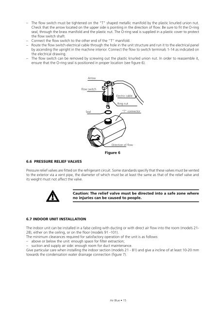
– The flow switch must be tightened on the “T” shaped metallic manifold by the plastic knurled union nut.<br />
Check that the arrow located on the upper side is pointing in the direction of flow. Be sure to fit the O-ring<br />
seal, through the brass manifold and the plastic nut. The O-ring seal is supplied in a plastic cover to protect<br />
the flow switch shaft.<br />
– Connect the flow switch to the other end of the “T” manifold.<br />
– Route the flow switch electrical cable through the hole in the unit structure and run it to the electrical panel<br />
by ascending the upright in the machine interior. Connect the flow to switch terminals 1-14 as indicated on<br />
the electrical drawing.<br />
– The flow switch can be removed by screwing out the plastic knurled union nut. In order to reassemble it,<br />
ensure that the O-ring seal is positioned in proper location (see figure 6).<br />
6.6 PRESSURE RELIEF VALVES<br />
Arrow<br />
Flow switch<br />
Seal<br />
Figure 6<br />
Electric cable<br />
Ring nut<br />
<strong>Air</strong> Blue • 15<br />
“T” connector<br />
Direction of flow<br />
Pressure relief valves are fitted on the refrigerant circuit. Some standards specify that these valves must be vented<br />
to the exterior via a vent pipe, the diameter of which must be at least the same as that of the relief valve and<br />
its weight must not affect the valve.<br />
6.7 INDOOR UNIT INSTALLATION<br />
Caution: The relief valve must be directed into a safe zone where<br />
no injuries can be caused to people.<br />
The indoor unit can be installed in a false ceiling with ducting or with direct air flow into the room (models 21-<br />
28), either on the ceiling, or on the floor (models 91 -101).<br />
The minimum clearances required for satisfactory operation of the unit is as follows:<br />
– above or below the unit: enough space for filter extraction;<br />
– suction and supply air side: enough room for duct maintenance.<br />
Give particular care when installing the indoor section (models 21 - 81) and give a incline of at least 10-20 mm<br />
towards the condensation water drainage connection (figure 7).