KAPPA V ECHOS AC IOM.pdf - Industrial Air
KAPPA V ECHOS AC IOM.pdf - Industrial Air
KAPPA V ECHOS AC IOM.pdf - Industrial Air

You also want an ePaper? Increase the reach of your titles
YUMPU automatically turns print PDFs into web optimized ePapers that Google loves.
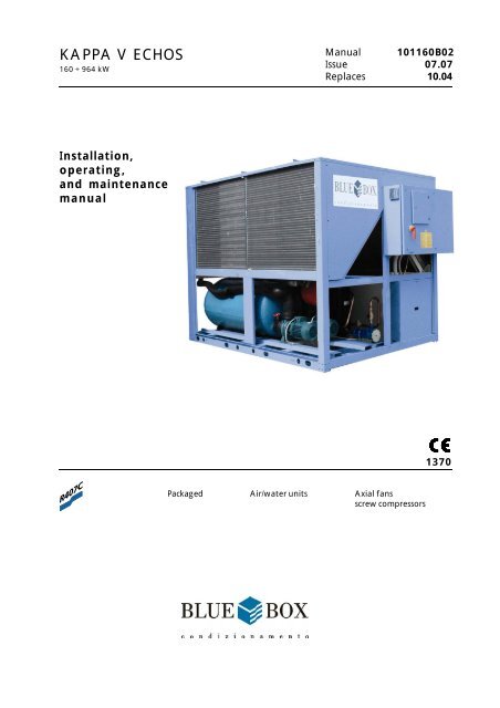
<strong>KAPPA</strong> V <strong>ECHOS</strong><br />
160 ÷ 964 kW<br />
Installation,<br />
operating,<br />
and maintenance<br />
manual<br />
Manual 101160B02<br />
Issue 07.07<br />
Replaces<br />
10.04<br />
Packaged <strong>Air</strong>/water units Axial fans<br />
screw compressors<br />
1370
INDEX<br />
<strong>KAPPA</strong> V <strong>ECHOS</strong> water chiller ..................................................................................... 1<br />
SERIES ......................................................................................................................... 4<br />
TECHNICAL DATA ...................................................................................................... 6<br />
1 FIELD OF APPLICATION ............................................................................................... 11<br />
2 INSPECTION, TRANSPORT, SITE HANDLING ................................................................ 11<br />
3 NON APLICABLE APPLICATIONS ................................................................................. 13<br />
4 SAFETY PRECAUTIONS................................................................................................ 14<br />
5 POSITIONING ............................................................................................................... 22<br />
6 INSTALLATION ............................................................................................................ 23<br />
7 START-UP .................................................................................................................... 40<br />
8 CHECKS DURING OPERATION ..................................................................................... 48<br />
9 CALIBRATION OF CONTROL EQUIPMENT .................................................................... 49<br />
10 MAINTENANCE AND PERIODIC CHECKS .................................................................... 50<br />
11 TROUBLESHOOTING .................................................................................................... 52<br />
12 DECOMMISSIONING THE UNIT ................................................................................... 61<br />
OVERALL DIMENSIONS, WEIGHTS AND HYDRAULIC CONNECTIONS .......................... 62<br />
REFRIGERANT CIRCUIT ................................................................................................ 76<br />
Blue Box
Blue Box
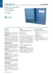
<strong>KAPPA</strong> V <strong>ECHOS</strong> water chiller<br />
<strong>Air</strong> cooled water chillers and heat pumps with semi-hermetic screw compressors and plate type evaporators.<br />
Composition of standard units:<br />
UNIT FRAME<br />
Self supporting frame constructed from galvanized sheet steel with polyester powder colour RAL 5014 paint<br />
baked at 180°C to provide a durable weatherproof finish. Threaded fasteners in stainless steel. Painted steel<br />
mesh guard supplied as standard, to protect the condenser coil against impact.<br />
COMPRESSORS<br />
Direct drive semi-hermetic screw compressors with continuous capacity step control from 30% to 100%, to<br />
maximize the unit performances in all working conditions. Start and shut off of unit at 12% of capacity.<br />
Crankcase heater and lubrication through pressure difference between suction and discharge pressure. Independent<br />
refrigerant circuits.<br />
Electronic motor protection via thermal sensors embedded in the windings and in the discharge pipe. Star-Delta<br />
start.<br />
CONDENSER<br />
Composed of a high efficiency coil manufactured from copper tubes and aluminium fins. The V shaped condensing<br />
coils result in a reduction of overall unit dimensions and an increase in the coil surface area leaving a space for the<br />
refrigerant circuit and hydraulic circuit components, if present.<br />
Units with two compressors have autonomously operating condensing sections of the two circuits.<br />
CONDENSER FANS<br />
Axial fans, with sickle shaped blades and special bell mouth designed to reduce noise, directly coupled to a three<br />
phase 6 pole motor with internal Klixon overload protection. Motor protection category is IP 54. The fan is<br />
equipped with a safety grille.<br />
EVAPORATOR<br />
Brazed plate type in 316 AISI stainless steel thermally insulated with closed cell expanded material for units size<br />
16.1 to 53.1. Units size 32.2-36.2-40.2 have brazed plate type heat exchanger with 2 circuits and a unique<br />
hydraulic connection, while units size 46.2,48.1 and 53.2 have two brazed plate type heat exchangers and a<br />
water manifold.<br />
The use of plate type heat exchangers provides:<br />
- an improved COP/EER<br />
- a reduced refrigerant charge<br />
- a reduced unit weight and dimension<br />
- a reduction in maintenance<br />
Each unit is equipped as standard with the flow switch already assembled.<br />
REFRIGERANT CIRCUIT<br />
Comprising: compressor discharge shut-off valve, liquid valve, charge connection, liquid line sight-glass, filter/<br />
dryer with interchangeable solid cartridge, thermostatic expansion valve with external pressure equalisation, high<br />
and low pressure values and relative condensation and evaporation temperatures are measured by pressure<br />
transducers that relay signals that are displayed on the controller. High and low pressure switches and safety<br />
valves.<br />
Device to shut-off the liquid line during compressor stops.<br />
ELECTRICAL PANEL<br />
The electrical panel includes:<br />
- Main switch<br />
- fuses to protect auxiliary and power circuits<br />
- compressor contactors<br />
- fan contactors<br />
The microprocessor controls the following functions:<br />
- water temperature regulation, with leaving water temperature control<br />
- freeze protection<br />
- compressor time intervals<br />
Blue Box 1
- compressor start sequence and automatic lead/lag selection<br />
- alarm signalling<br />
- alarm reset<br />
- capacity steps<br />
- common alarm contact for remote signalling<br />
- automatic capacity step reduction when high pressure limit is reached<br />
- recording of historical alarm data<br />
LCD display of the following information:<br />
- water outlet temperature<br />
- programmed temperature set-point and differential<br />
- alarm descriptions<br />
- compressor hours run meter, number of unit and compressor starts and pumps (if installed)<br />
- high and low pressure values and relative condensation and evaporation temperature values.<br />
- discharge gas temperature<br />
Electric power supply [V/f/Hz]: 400/3~/50 ±5%<br />
CONTROLS AND SAFETY DEVICES<br />
- double safety high pressure switch with manual reset<br />
- High pressure safety, with automatic reset, controlled by the unit controller<br />
- Low pressure safety switch, with automatic reset, controlled by the unit controller<br />
- High pressure relief valve<br />
- freeze protection probe at the outlet of each evaporator<br />
- chilled water temperature probe (located at evaporator inlet)<br />
- mechanical flow switch<br />
- compressor and fan over-temperature protection<br />
- Compressor cooling device with liquid injection.<br />
TESTING<br />
Units are subjected to a factory test and supplied complete with oil and refrigerant.<br />
<strong>KAPPA</strong> V <strong>ECHOS</strong> UNIT VERSIONS<br />
<strong>KAPPA</strong> V <strong>ECHOS</strong> /HP: reverse cycle heat pump<br />
In addition to the components of version <strong>KAPPA</strong> V <strong>ECHOS</strong>, this unit includes:<br />
Refrigerant circuit: 4-way reversing valve, suction separator, liquid receiver, second thermostatic expansion valve.<br />
Microprocessor enabled for summer/winter changeover and automatic defrost independently controlled for each<br />
compressor, with a patented Blue Box logic, to obtain the maximum efficiency in the intervention and duration of<br />
defrost cycles.<br />
HYDRAULIC MODULE OPTIONS<strong>KAPPA</strong> V <strong>ECHOS</strong> 2PS: unit with storage tank and pumps.<br />
In addition to the components of version <strong>KAPPA</strong> V <strong>ECHOS</strong> this unit includes:<br />
insulated storage tank; run and standby circulating pumps, with automatic changeover by time or fault.<br />
Expansion tank, check valves and gate valves.<br />
Version ST is available in the following additional three configurations:<br />
- ST 1PS: with 1 pump and a tank;<br />
- ST 1P: with 1 pump without a tank.<br />
- ST 2P: with 2 pumps without a tank<br />
<strong>AC</strong>CESSORY VERSIONS<br />
<strong>KAPPA</strong> V <strong>ECHOS</strong> /DC: unit with heat recovery condenser<br />
In addition to the components of version <strong>KAPPA</strong> V <strong>ECHOS</strong> this unit includes, in each refrigerant circuit, a 100%<br />
heat recovery brazed plate type condenser for the production of hot water and a liquid receiver. The recovery<br />
condenser is a brazed plate type for models 16.1 and 32.2 and shell and tube for the remainder of the range.<br />
The microprocessor automatically controls the water temperature and the high-pressure heat recovery safety<br />
switch.<br />
For the maximum efficiency of the device it is advisable to couple with fan speed control. Not available on HP<br />
version.<br />
Blue Box 2
<strong>KAPPA</strong> V <strong>ECHOS</strong> /DS: unit with desuperheater<br />
In addition to the components of version <strong>KAPPA</strong> V <strong>ECHOS</strong> this unit includes a heat recovery brazed plate type<br />
condenser for condensation partial heat recovery (20%) arranged in series for each circuit with the condenser<br />
coil. For the maximum efficiency of the device it is advisable to couple with fan speed control. Also available on<br />
all HP models. In this case an isolating valve must be fitted on the water recovery circuit and be closed during heat<br />
pump mode operation as described in the manual.<br />
<strong>KAPPA</strong> V <strong>ECHOS</strong> /LN: low noise unit<br />
In addition to the components of version <strong>KAPPA</strong> V <strong>ECHOS</strong> this unit includes:<br />
An internally lined sound absorbing compressor compartment, with absorption material having an intermediate<br />
layer of high acoustic impedance material, and fan speed control. The fan speed is automatically increased in<br />
accordance with the ambient conditions.<br />
<strong>KAPPA</strong> V <strong>ECHOS</strong> /SLN: extra low noise unit<br />
In addition to the components of version <strong>KAPPA</strong> V <strong>ECHOS</strong>/LN this unit includes:<br />
An increased coil surface area, slower fan speed 8 pole motors and fan speed control.<br />
REFRIGERANT CIRCUIT <strong>AC</strong>CESSORIES<br />
- Electronic expansion valve<br />
- Condensing pressure control by fan speed regulator for low ambient temperature operation<br />
- Dual set-point (high/low temperature) with unique electronic thermostatic valve. The evaporator of the unit is<br />
sized according to the higher operating temperature. The two set-points can be programmed and switched<br />
between them from the keypad or using a digital input; the type of selection must be specified at the time of the<br />
order.<br />
- High and low pressure gauges are available ,as an option, for all models. As standard on all units low pressure<br />
values and relative, condensation and evaporation temperatures are measured by pressure transducers that<br />
relay signals that are displayed on the controller.<br />
- Liquid receiver (standard for version /HP, /DC);<br />
- Compressor suction valves;<br />
- Liquid line solenoid valve. The units have as standard a device which,at the compressor stop, closes the liquid<br />
line and consequently the expansion valve;<br />
- low water temperature kit.<br />
HYDRAULIC CIRCUIT <strong>AC</strong>CESSORIES<br />
- Anti-freeze evaporator heater, also on recovery heat exchangers if available. ST version also has an anti-freeze<br />
heater on the hydraulic circuit and storage tank<br />
- Water side relief valve (version ST only).<br />
ELECTRICAL <strong>AC</strong>CESSORIES<br />
- Serial interface RS485 type with Carel, Modbus, Echelon and Bacnet protocols. Compatibility with Trend and<br />
Johnson supervisions.<br />
- Power factor correction cos f ≥ 0.9 at nominal operating conditions; on external IP 55 electric panel on<br />
external IP 55 electric panel (connections to power supply are the responsibility of the installer; accessory<br />
connected to potential free contacts)<br />
- Remote user terminal panel (in addition to the standard terminal)<br />
- Set point variable with remote signal (0-1V, 0-10V, 0-20mA, 4-20mA)<br />
- Single voltage-free contacts for machine status signals<br />
- 3 levels of alarm priority<br />
- SMS availability for assistance management<br />
- Limitation of absorbed current<br />
Blue Box 3
SERIES<br />
The <strong>KAPPA</strong> V <strong>ECHOS</strong> series of air cooled chillers and heat pumps, are available in various sizes with capacities<br />
from 160 to 534 kW (capacities refer to water entering/leaving 12/7 °C, ambient air 35 °C) in the following basic<br />
versions:<br />
- <strong>KAPPA</strong> V <strong>ECHOS</strong> cooling only<br />
- <strong>KAPPA</strong> V <strong>ECHOS</strong>/HP heat pump<br />
TYPE DESIGNATION<br />
unit type series /version /option hydraulic modul /accessory version SIZE<br />
<strong>KAPPA</strong> V <strong>ECHOS</strong> 16.1<br />
/HP /ST 1P /LN 20.1<br />
/ST 2P /DS 27.1<br />
/ST 1PS /DC 32.2<br />
/ST 2PS /SLN 36.1<br />
36.2<br />
38.1<br />
40.2<br />
46.2<br />
48.1<br />
53.2<br />
Meaning of values<br />
TYPE DESIGNATION<br />
MODEL<br />
Type designation example: <strong>KAPPA</strong> V <strong>ECHOS</strong> /HP/DS 38.1<br />
38 . 1<br />
Number to identify the indicative<br />
cooling capacity (in this case 380kW) Number of compressors<br />
Blue Box 4
The model, serial number, characteristics, power supply, etc. are shown by means of decals on the unit.<br />
Modello/Model<br />
Modell/Modèle<br />
Tipo refrigerante<br />
Refrigerant type<br />
Kältemitteltyp<br />
Type rèfrigèrant<br />
Corrente massima assorbita<br />
Max. absorbed current<br />
Max.Stromaunfnahme<br />
Courant maxi absorbée<br />
Tensione-Fasi-Frequenza<br />
Voltage-Phases-Frequency<br />
Spannung-Phasen-Frequenz<br />
Tension-Phases-Fréquence<br />
Numero circuiti refrigerante<br />
Refrigerant circuit number<br />
Anzahl der K ältekreise<br />
Nombre circuits réfrigérant IP quadro elettrico<br />
IP electrical panel<br />
IP Schaltschrank<br />
IP tableau électrique<br />
Corrente massima di spunto<br />
Max starting current<br />
Max. Anlaufstrom<br />
Courant maxi de démarrage<br />
Tensione circuiti ausiliari<br />
Auxiliary circuit voltage<br />
Steuerspannung<br />
Tension circuits auxiliares<br />
Press. massima circuito idraulico Data di produzione<br />
Max. hydraulic circuit pressure Date of manufacture<br />
Max. zulässigerDruck<br />
im Wassersystem Herstellungstatum<br />
Press. Maxi circuit hydraulique Date de production<br />
kPa<br />
bar<br />
Blue Box 5<br />
Matricola<br />
Serial number<br />
Seriennumer<br />
Matricule<br />
A A<br />
Carica refrigerante per circuito(kg)/Refrigerant charge per circuit(kg)<br />
Kältemittel Füllmenge je Kreislauf (kg)/ Charge r éfrigérant par circuit(kg)<br />
C2<br />
C1 C3 C4<br />
MODELLO - MODELE - MODEL - TYP<br />
MATRICOLA - MATRICULE - SERIAL NO. - SERIENUMMER<br />
Press. max refriger. alta/bassa<br />
Max. Refrig. pressure high/low<br />
Max. N/n Kaltemrttelbetriebsaruck<br />
Pression maxi refrig. haute/basse<br />
REFRIGERANTE - REFRIGERANT - KÄLTEMITTEL - REFRIGERANT<br />
kPa<br />
bar
TECHNICAL DATA<br />
(1) total water flow<br />
(*) ambient air temperature 35 °C; evaporator entering/leaving water temperature 12-7 °C;.<br />
(**) ambient air temperature 8 °C DB, 70%RH; condenser entering/leaving water temperature 40-45 °C.<br />
Blue Box 6<br />
Refrigerant R407C<br />
MODEL <strong>KAPPA</strong> V <strong>ECHOS</strong><br />
Cooling (*)<br />
16.1 20.1 27.1 32.2 36.1 36.2<br />
Nominal capacity kW 160,4 198,4 266,9 320,8 359,2 358,7<br />
Evaporator water flow (1) l/s 7,662 9,7478 12,753 15,325 17,161 17,14<br />
l/h (27585) (34120) (45911) (55169) (61779) (61704)<br />
Evaporator pressure drop<br />
Heating (**)<br />
kPa 36,7 30,3 38 34,8 34,1 28,6<br />
Nominal capacity kW 164,7 199,6 275,5 329,5 357,6 364,3<br />
Condenser water flow (1) l/s 7,871 9,535 13,165 15,742 17,087 17,406<br />
l/h (28336) (34328) (47394) (56671) (61514) (62663)<br />
Condenser pressure drop kPa 36,6 30,7 40,5 36,6 33,8 29,5<br />
Compressors type<br />
Quantity n 1 1 1 2 1 2<br />
Absorbed power cooling (*) kW 57,6 72 94,4 115,2 120,5 129,6<br />
Absorbed power heating (**) kW 57,8 70,4 93,3 115,6 117,9 128,2<br />
Capacity steps % 0-40 0-40 0-40 0-20-40 0-40 0-20-40<br />
70-100 70-100 70-100 55-70-85 70-100 55-70-85<br />
Condenser cooling fans type<br />
Total air flow m 3 /s 17,5 17 23,333 35 34 34,5<br />
m 3 semihermetic screw<br />
axial<br />
/h (63000) (61200) (84000) (126000) (122400) (124200)<br />
Fan motor power n x kW 3 x 2,0 3 x 2,0 4 x 2,0 6 x 2,0 6 x 2,0 6 x 2,0<br />
Nominal revolution speed RPM<br />
900<br />
Electric motor supply<br />
Refrigerant charge<br />
V/Ph/Hz<br />
400V 3 ~ 50Hz<br />
Chiller version kg 1 x 45 1 x 58 1 x 85 1 x 48 1 x 117 1x 46<br />
1x 59<br />
Heat pump version<br />
Oil<br />
kg 1 x 54 1 x 70 1 x 101 1 x 57 1 x 139 1 x 55<br />
1 x 70<br />
Oil charge kg 1 x 7,5 1 x 7,5 1 x 10 2 x 7,5 1 x 10 2 x 7,5<br />
Oil type<br />
Evaporator type<br />
FVC68D<br />
plate<br />
Heat exchanger water volume l 14,1 15,7 21,6 28,6 32,6 2 x 18,6<br />
Max operating pressure water side<br />
Dimension and weight<br />
bar<br />
30<br />
Length mm 4.246 4.246 3.246 4.251 4.246 4.251<br />
Width mm 1.246 1.246 2.315 2.276 2.280 2.276<br />
Heigth mm 2.368 2.368 2.368 2.368 2.368 2.368<br />
Shipping weight kg 1.576 1.642 2.104 2.941 2.633 3043
TECHNICAL DATA<br />
MODEL <strong>KAPPA</strong> V <strong>ECHOS</strong><br />
Cooling (*)<br />
38.1 40.2 46.2 48.1 53.2<br />
Nominal capacity kW 383,9 396,7 465,3 482,2 533,9<br />
Evaporator water flow (1) l/s 18,34 18,955 22,231 23,041 25,506<br />
l/h (66022) (68239) (80031) (82946) (91823)<br />
Evaporator pressure drop<br />
Heating (**)<br />
kPa 31,9 34,9 34,4 31 38<br />
Nominal capacity kW 393,7 399,2 475,1 485,2 551,1<br />
Condenser water flow (1) l/s 18,812 19,071 22,7 23,181 26,33<br />
l/h (67723) (68655) (81721) (83452) (94788)<br />
Condenser pressure drop kPa 33,5 35,3 35,8 31,4 40,5<br />
Compressors type<br />
Quantity n 1 2 2 2 2<br />
Absorbed power cooling (*) kW 139,6 143,9 166,3 174 188,7<br />
Absorbed power heating (**) kW 139,2 140,8 163,7 168,3 186,6<br />
Capacity steps % 0-40 0-20-40 0-20-40 0-40 0-20-40<br />
70-100 55-70-85 55-70-85 70-100 55-70-85<br />
Condenser cooling fans type<br />
Total air flow m 3 /s 34 34 46,667 46,667 46,667<br />
m 3 Halbhermetik Schrauben<br />
Axial<br />
/h (122400) (122400) (168000) (168000) (168000)<br />
Fan motor power n x kW 6 x 2,0 6 x 2,0 8 x 2,0 8 x 2,0 8 x 2,0<br />
Nominal revolution speed RPM<br />
900<br />
Electric motor supply<br />
Refrigerant charge<br />
V/Ph/Hz<br />
400V 3 ~ 50Hz<br />
Chiller version kg 1 x 118 2 x 59 1 x 84<br />
1x 85<br />
1 x 89 2 x 85<br />
Heat pump version<br />
Oil<br />
kg 1 x 141 2 x 70 1 x 100<br />
1x 101<br />
1 x 10⁶ 2 x 101<br />
Oil charge kg 1 x 14 2 x 7,5 1 x 7,5<br />
1 x 10<br />
1 x 14 2 x 10<br />
Oil type<br />
Evaporator type<br />
Heat exchanger water volume l 38 2 x 18.6 38 43,2 2 x 21.6<br />
Max operating pressure water side bar 30 30 30 30 30<br />
Dimension and weight<br />
Length mm 4.246 4.251 5.751 5.746 5.751<br />
Width mm 2.280 2.276 2.276 2.276 2.276<br />
Heigth mm 2.368 2.368 2.368 2.368 2.368<br />
Shipping weight kg 2.633 3.145 3.780 3.428 4.040<br />
(1) total water flow<br />
(*) ambient air temperature 35 °C; evaporator entering/leaving water temperature 12-7 °C;.<br />
(**) ambient air temperature 8 °C DB, 70%RH; condenser entering/leaving water temperature 40-45 °C.<br />
Blue Box 7<br />
FVC68D<br />
Platten<br />
Refrigerant R407C
ELECTRICAL CHAR<strong>AC</strong>TERISTICS AND COMPONENTS<br />
Blue Box 8<br />
Refrigerant R407C<br />
MODEL <strong>KAPPA</strong> V <strong>ECHOS</strong> 16.1 20.1 27.1 32.2 36.1 36.2<br />
Maximum absorbed power (1) Kw 73,4 90,6 122,7 141,4 158,1 158,6<br />
Maximum starting current A 245,6 353,63 397,7 368,5 481,5 476,5<br />
A (252) (360) (409) (380) (493) (488)<br />
Full load current (2) A 132,6 163,6 221,7 255,5 285,5 286,5<br />
A (139) (170) (233) (267) (297) (298)<br />
Fan motor nominal power n x kW 3 x 6 3 x 6 4 x 8 6 x 12 6 x 12 6 x 12<br />
Fan motor nominal absorbed current n x A 3 x 4 3 x 4 4 x 4 6 x 4 6 x 4 6 x 4<br />
Pump motor nominal power n x kW 1 x 3 1 x 3 1x 5,5 1x 5,5 1x 5,5 1x 5,5<br />
Pump motor nominal absorbed power n x A 1 x 6.37 1 x 6.37 1 x 11.3 1 x 11.5 1 x 11.5 1 x 11.5<br />
Power supply V/Ph/Hz<br />
Control power supply V/Ph/Hz<br />
(1) mains power supply to allow unit operation.<br />
(2) maximum current before safety cut-outs stop the unit. This value is never exceeded and must be used to size the electrical supply<br />
cables and relevant safety devices (refer to electrical wiring diagram supplied with the unit).<br />
All values in brackets are refer to /ST version (units with storage tank) or units with pump.<br />
400V 3 ~ 50Hz ±5% V<br />
230V 1 ~ 50Hz ±5% V<br />
MODEL <strong>KAPPA</strong> V <strong>ECHOS</strong> 38.1 40.2 46.2 48.1 53.2<br />
Maximum absorbed power (1) Kw<br />
Kw<br />
178,0 176,3 208,4 223,9 238,3<br />
Maximum starting current A 585,5 507,5 552,5 676,5 606,5<br />
A (603) (525) (570) (694) (624)<br />
Full load current (2) A 321,5 318,5 376,5 404,5 430,5<br />
A (339) (336) (394) (422) (448)<br />
Fan motor nominal power n x kW 6 x 12 6 x 12 8 x 16 8 x 16 8 x 16<br />
Fan motor nominal absorbed current n x A 6 x 4 6 x 4 8 x 4 8 x 4 8 x 4<br />
Pump motor nominal power n x kW 1 x 9.2 1 x 9.2 1 x 9.2 1 x 9.2 1 x 9.2<br />
Pump motor nominal absorbed power n x A 1x 17.5 1x 17.5 1x 17.5 1x 17.5 1x 17.5<br />
Power supply V/Ph/Hz<br />
Control power supply V/Ph/Hz<br />
400V 3 ~ 50Hz ±5% V<br />
230V 1 ~ 50Hz ±5% V
TECHNICAL DATA - <strong>KAPPA</strong> V <strong>ECHOS</strong> /ST 2PS<br />
Blue Box 9<br />
Refrigerant R407C<br />
MODEL <strong>KAPPA</strong> V <strong>ECHOS</strong> 16.1 20.1 27.1 32.2 36.1 36.2<br />
Pump section<br />
Evaporator water flow l/s 7,662 9,7478 12,753 15,325 17,161 17,14<br />
l/h (27585) (34120) (45911) (55169) (61779) (61704)<br />
Pump nominal power kW 3,0 3,0 5,5 5,5 5,5 5,5<br />
External available pressure kPa 225 199 246 227 208 214<br />
Storage tank water volume l 450 450 585 740 740 740<br />
Dimension and weight<br />
Length mm 4.246 4.246 3.246 4.251 4.246 4.251<br />
Width mm 1.246 1.246 2.315 2.276 2.280 2.276<br />
Heigth mm 2.368 2.368 2.368 2.368 2.368 2.368<br />
Shipping weight kg 1.704 1.778 2.294 3.163 2.859 3267<br />
MODEL <strong>KAPPA</strong> V <strong>ECHOS</strong> 38.1 40.2 46.2 48.1 53.2<br />
Pump section<br />
Evaporator water flow l/s 18,34 18,955 22,231 23,041 25,506<br />
l/h (66022) (68239) (80031) (82946) (91823)<br />
Pump nominal power kW 9,2 9,2 9,2 9,2 9,2<br />
External available pressure kPa 265 261 252 252 234<br />
Storage tank water volume l 740 740 740 740 740<br />
Dimension and weight<br />
Length mm 4.246 4.251 5.751 5.746 5.751<br />
Width mm 2.280 2.276 2.276 2.276 2.276<br />
Heigth mm 2.368 2.368 2.368 2.368 2.368<br />
Shipping weight kg 3.128 3.453 4128 3.776 4.386
SOUND POWER AND PRESSURE LEVELS<br />
STANDARD UNITS<br />
<strong>KAPPA</strong><br />
V <strong>ECHOS</strong><br />
Lw Lp Lw Lp Lw Lp Lw Lp Lw Lp Lw Lp Lw Lp Lw Lp Lw Lp<br />
16.1 88,0 69,0 86,0 67,0 91,0 72,0 90,0 71,0 90,0 71,0 85,0 66,0 79,0 60,0 72,0 53,0 93,0 74,0<br />
20.1 88,0 69,0 86,0 67,0 91,0 72,0 90,0 71,0 90,0 71,0 85,0 66,0 79,0 60,0 72,0 53,0 93,0 74,0<br />
27.1 86,0 67,0 90,0 71,0 91,0 72,0 88,0 69,0 92,0 73,0 88,0 69,0 82,0 63,0 73,0 54,0 95,0 76,0<br />
32.2 91,0 71,0 89,0 69,0 94,0 74,0 93,0 73,0 93,0 73,0 88,0 68,0 82,0 62,0 75,0 55,0 96,0 76,0<br />
36.1 91,0 71,0 89,0 69,0 94,0 74,0 93,0 73,0 93,0 73,0 88,0 68,0 82,0 62,0 75,0 55,0 96,0 76,0<br />
36.2 91,0 71,0 89,0 69,0 94,0 74,0 93,0 73,0 93,0 73,0 88,0 68,0 82,0 62,0 75,0 55,0 96,0 76,0<br />
38.1 91,0 71,0 89,0 69,0 94,0 74,0 93,0 73,0 93,0 73,0 88,0 68,0 82,0 62,0 75,0 55,0 96,0 76,0<br />
40.2 91,0 71,0 89,0 69,0 94,0 74,0 93,0 73,0 93,0 73,0 88,0 68,0 82,0 62,0 75,0 55,0 96,0 76,0<br />
46.2 89,0 69,0 93,0 73,0 94,0 74,0 91,0 71,0 95,0 75,0 91,0 71,0 85,0 64,0 76,0 56,0 98,0 78,0<br />
48.1 89,0 69,0 93,0 73,0 94,0 74,0 91,0 71,0 95,0 75,0 91,0 71,0 85,0 64,0 76,0 56,0 98,0 78,0<br />
53.2 89,0 69,0 93,0 73,0 94,0 74,0 91,0 71,0 95,0 75,0 91,0 71,0 85,0 64,0 76,0 56,0 98,0 78,0<br />
LOW NOISE UNITS<br />
<strong>KAPPA</strong><br />
V <strong>ECHOS</strong><br />
63<br />
dB<br />
Oktavbereiche [Hz]<br />
125 250 500 1000 2000 4000 8000<br />
dB dB dB dB<br />
Lw: sound power values in free field conditions are calculated in accordance with ISO 3746.<br />
Lp : sound pressure values measured at 1 m from the unit in free field conditions in compliance with ISO 3746<br />
Blue Box 10<br />
dB dB dB<br />
Gesamt<br />
Lw Lp Lw Lp Lw Lp Lw Lp Lw Lp Lw Lp Lw Lp Lw Lp Lw Lp<br />
16.1 88,0 69,0 80,0 61,0 87,0 68,0 86,0 67,0 87,0 68,0 80,0 61,0 74,0 55,0 68,0 49,0 90,0 71,0<br />
20.1 89,0 70,0 80,0 61,0 88,0 69,0 86,0 67,0 87,0 68,0 81,0 62,0 75,0 55,0 68,0 49,0 90,0 71,0<br />
27.1 84,0 65,0 88,0 69,0 89,0 70,0 87,0 68,0 88,0 69,0 86,0 67,0 78,0 59,0 72,0 53,0 92,0 73,0<br />
32.2 91,0 72,0 83,0 63,0 90,0 71,0 89,0 69,0 90,0 70,0 83,0 64,0 77,0 58,0 71,0 51,0 93,0 73,0<br />
36.1 92,0 72,0 83,0 63,0 91,0 71,0 89,0 69,0 90,0 70,0 84,0 64,0 78,0 58,0 71,0 51,0 93,0 73,0<br />
36.2 92,0 72,0 83,0 63,0 91,0 71,0 89,0 69,0 90,0 70,0 84,0 64,0 78,0 58,0 71,0 51,0 93,0 73,0<br />
38.1 92,0 72,0 83,0 63,0 91,0 71,0 89,0 69,0 90,0 70,0 84,0 64,0 78,0 58,0 71,0 51,0 93,0 73,0<br />
40.2 92,0 72,0 83,0 63,0 91,0 71,0 89,0 70,0 90,0 70,0 84,0 64,0 78,0 58,0 71,0 51,0 93,0 73,0<br />
46.2 87,0 67,0 91,0 71,0 92,0 72,0 90,0 70,0 91,0 70,0 89,0 69,0 81,0 60,0 75,0 54,0 95,0 75,0<br />
48.1 87,0 67,0 91,0 71,0 92,0 72,0 90,0 70,0 91,0 70,0 89,0 69,0 81,0 60,0 75,0 54,0 95,0 75,0<br />
53.2 87,0 67,0 91,0 71,0 92,0 72,0 90,0 70,0 91,0 70,0 89,0 69,0 81,0 60,0 75,0 54,0 95,0 75,0<br />
EXTRA LOW NOISE UNITS<br />
<strong>KAPPA</strong><br />
V <strong>ECHOS</strong><br />
dB(A)<br />
Octave band [Hz]<br />
63 125 250 500 1000 2000 4000 8000 Total<br />
dB dB dB dB dB dB dB dB dB(A)<br />
Octave band [Hz]<br />
63 125 250 500 1000 2000 4000 8000 Total<br />
dB dB dB dB dB dB dB dB dB(A)<br />
Lw Lp Lw Lp Lw Lp Lw Lp Lw Lp Lw Lp Lw Lp Lw Lp Lw Lp<br />
16.1 89,0 70,0 77,0 58,0 85,0 65,0 85,0 65,0 85,0 66,0 77,0 58,0 71,0 52,0 65,0 46,0 88,0 68,0<br />
20.1 90,0 71,0 77,0 58,0 85,0 66,0 85,0 66,0 85,0 66,0 78,0 59,0 71,0 52,0 65,0 46,0 88,0 69,0<br />
27.1 82,0 63,0 83,0 64,0 84,0 65,0 83,0 64,0 86,0 66,0 85,0 65,0 78,0 59,0 70,0 51,0 90,0 71,0<br />
32.2 92,0 73,0 80,0 60,0 88,0 68,0 88,0 68,0 88,0 68,0 80,0 61,0 74,0 54,0 68,0 48,0 91,0 71,0<br />
36.1 93,0 73,0 80,0 60,0 88,0 68,0 88,0 68,0 88,0 68,0 81,0 61,0 74,0 55,0 68,0 49,0 91,0 71,0<br />
36.2 93,0 73,0 80,0 60,0 88,0 68,0 88,0 68,0 88,0 68,0 81,0 61,0 74,0 55,0 68,0 49,0 91,0 71,0<br />
38.1 93,0 73,0 80,0 60,0 88,0 68,0 88,0 68,0 88,0 68,0 81,0 61,0 74,0 55,0 68,0 49,0 91,0 71,0<br />
40.2 93,0 73,0 80,0 60,0 88,0 68,0 88,0 68,0 88,0 68,0 81,0 61,0 74,0 55,0 68,0 49,0 91,0 71,0<br />
46.2 85,0 64,0 86,0 65,0 87,0 66,0 86,0 65,0 89,0 68,0 88,0 67,0 81,0 60,0 73,0 53,0 93,0 72,0<br />
48.1 85,0 64,0 86,0 65,0 87,0 66,0 86,0 65,0 89,0 68,0 88,0 67,0 81,0 60,0 73,0 53,0 93,0 72,0<br />
53.2 85,0 64,0 86,0 65,0 87,0 66,0 86,0 65,0 89,0 68,0 88,0 67,0 81,0 60,0 73,0 53,0 93,0 72,0
1. FIELD OF APPLICATION<br />
The equipment is designed for cooling (chiller only versions) or cooling/heating (heat pump versions) water, which<br />
is usually applied to air conditioning or refrigeration systems. Units must be used exclusively within the operating<br />
limits specified in Section 6.15.7.<br />
1.1 INTRODUCTION<br />
- When installing or servicing the unit, it is necessary to strictly follow the rules described in this manual, to<br />
conform to all the items detailed on the unit labels and take any necessary precaution.<br />
- Pressure in refrigerant circuits and danger from electrical shock can be hazardous when installing or servicing the<br />
unit.<br />
2. INSPECTION, TRANSPORT, SITE HANDLING<br />
2.1 INSPECTION<br />
Any work on the unit must be carried out only by trained personnel.<br />
Attention: before repairing or servicing the unit, ensure that the<br />
electrical supply is disconnected.<br />
The warranty will be invalid if the rules described in this manual are not observed and if any modifications are<br />
made to the unit without prior authorisation of the manufacturer.<br />
After receiving the unit, immediately check its integrity. The unit will have left the factory in perfect condition<br />
therefore on receiving the unit any damage must be verbally described to the carrier and recorded on the Delivery<br />
Note which must be signed by both parties. Blue Box or their Agent must be informed, as soon as possible, of the<br />
extent of the damage.<br />
The Customer should prepare a written statement and photographic evidence regarding any severe damage.<br />
2.2 UNP<strong>AC</strong>KING<br />
Unpack the unit with care so as not to damage the unit. Disposal of packing materials is the responsibility of the<br />
receiver and must be made in accordance with local and national regulations.<br />
Blue Box 11
2.3 LIFTING AND SITE HANDLING<br />
Avoid sudden movements and jolts when unloading and positioning the unit. Internal handling procedures must<br />
be conducted with care. Do not exert leverage on the components of the machine. The unit must be lifted by<br />
inserting steel tubes through the lifting attachments shown by the relative labels (yellow arrow).<br />
The unit must be lifted by harnessing it as shown in figure 1: use ropes or straps of sufficient length and spacer<br />
bars to avoid damage to the unit’s side panels and cover.<br />
4 m min.<br />
Caution: ensure that the method of lifting does not allow the unit to<br />
slip from chains and slings or turn-over or slide from lifting devices.<br />
2.5 m min.<br />
Figure 1<br />
Blue Box 12<br />
1<br />
2.5 m min.
All lifting devices, ropes and sling etc, must be selected by someone<br />
with the required knowledge and be fully responsible for the use<br />
thereof.<br />
The unit must be properly balanced and when using a forklift the<br />
forks should be in a low position.<br />
If the unit is not balanced apply ballast. Any protruding parts<br />
should not be supported by hand.<br />
Do not walk or stand beneath or in the proximity of the load.<br />
Transportation must be by specialised personnel (truck operators,<br />
hook-up personal), equipped with the necessary protection<br />
equipment (overalls, safety shoes, protective gloves, helmets,<br />
goggles).<br />
The manufacturer will not accept any responsibility in case of<br />
possible accidents due to the non-observance of these warnings.<br />
3 NON APLICABLE APPLICATIONS<br />
The unit should not be applied in the following circumstances:<br />
- In an explosive atmosphere;<br />
- In an inflammable atmosphere;<br />
- In excessively dusty environments;<br />
- By untrained personnel;<br />
- In any manner contrary to the rules in force.<br />
- With incorrect installation;<br />
- With defective power supply;<br />
- Without total or partial observance of instructions;<br />
- With lack of maintenance and/or use of non original spare parts;<br />
- With modifications or other changes unauthorized by the manufacturer;<br />
- Within a location that is not clear of debris or other objects;<br />
- Within a location that is inadequately cleared,<br />
- With anomalous vibrations in the location area.<br />
Blue Box 13
4. SAFETY PRECAUTIONS<br />
The unit has been designed in accordance with to the followings directives:<br />
DIRECTIVES<br />
98/37 CEE Units safety<br />
89/336 CEE Electromagnetic compatibility<br />
73/23 CEE Low tension<br />
97/23 CEE Devices under pressure<br />
RULES<br />
- EN 60204-1: Machinery safety - electric equipment of units<br />
12/1997 - Part 1: General rules<br />
- EN 50081-2: Electromagnetic compatibility – general rules on emission.<br />
08/1993 - Part 2: <strong>Industrial</strong> environment<br />
- EN 50082-2: Electromagnetic compatibility – general rules on immunity<br />
03/1995 - Part 2: <strong>Industrial</strong> environment<br />
- EN 292/2: Safety of machinery. General rules of design<br />
09/1991 - Part 2 a: Specifications and technical principles.<br />
- EN 294: Safety of machinery - Safety distance to avoid contact with upper limbs.<br />
06/1992<br />
- EN 349: Minimum distance to avoid crushing of parts of human body. .<br />
04/1993<br />
- EN 378-2: Devices under pressure – Refrigeration plants and heat pumps:<br />
01/2001 Safety and environmental requirements.<br />
- Part 2: Design, manufacture, test, installation, marking and documentation<br />
4.1 DEFINITION OF DANGER ZONE<br />
Only authorised operators must be allowed in the vicinity of the unit.<br />
- The external danger zone concerns a space of approximately 2 m in width around the perimeter of the machine.<br />
Access to this area must be prevented by suitable guarding in the event that the unit is located in an unprotected<br />
area that is easily accessible to unauthorised persons.<br />
- The interior of the unit is designated as a danger zone. Any access to this zone must be by qualified personnel<br />
only after all electrical power has been de-energised.<br />
Blue Box 14
4.2 SAFETY RULES<br />
The unit is designed and built in accordance with the PED 97/23CE rules, to ensure the maximum level of safety.<br />
To avoid possible situations of risk adhere to the following rules at all times:<br />
- All work on the unit must be performed by qualified personnel. Before working on the unit, ensure that the<br />
designated personnel are conversant with the documentation supplied.<br />
- Always ensure there is a copy of the documentation in the immediate vicinity of the unit.<br />
- The operations indicated in this manual must be integrated with the procedures of instruction manuals of other<br />
systems or devices assembled in the unit. The manuals contain all the necessary information to manage, in<br />
safety, all devices and the possible operating modes.<br />
- Use the appropriate personal safety equipment (gloves, helmet, safety goggles, safety footwear, etc.) for all<br />
maintenance and control operations on the unit.<br />
-Avoid loose garments, dangling accessories such as ties, chains, watches which could be entangled in moving<br />
parts of the unit.<br />
- Use only tools and equipment that are in good working order.<br />
- The compressor compartment contains various high temperature components. Adopt the maximum caution<br />
when working in the vicinity of the compressors and avoid touching any parts of the unit without appropriate<br />
protection.<br />
- Do not work within the theoretical discharge trajectory of the relief valves.<br />
-If components are located in positions easily accessed by non qualified people it is mandatory that protection<br />
grilles, available as an accessory option, are installed.<br />
- The user must consult the installation and operating section of this manual regarding the systems incorporated.<br />
- All units have safety / warning labels. It is forbidden to remove any safety /warning label.<br />
It is forbidden to<br />
- Remove or by-pass any safety measure for people protection.-<br />
- Tamper and/or modify, even partially, the safety devices of the unit.<br />
- In case of alarm signals, and the consequent intervention of safety devices, the operator must contact qualified<br />
maintenance technicians. A possible accident could cause serious injuries or death.<br />
- All safety devices must be verified according to the instruction manual. Verification and repair/adjustment must<br />
be performed by qualified personnel authorised with a written instruction by the customer. A copy of the results<br />
of the repair/adjustment made must be left on the unit. A possible accident could cause serious injuries or<br />
death.<br />
The Manufacturer is not responsible for any damage to people, pets or objects due to the re use of any part of the<br />
unit for functions or assemblies different to its original purpose.<br />
It is forbidden to tamper/change without authorisation any component of the unit.<br />
The use of accessories, tools or components different from those recommended by the Manufacturer exonerates<br />
the Manufacturer from any civil or penal responsibility.<br />
The operations of removal and demolition of the unit must be carried out only by personnel adequately trained<br />
and equipped.<br />
Blue Box 15
MECHANICAL HAZARDS<br />
Operating mode Analysed risk or hazard Solution adopted<br />
Normal operating regime Stability Because of their intrinsic characteristics, the<br />
units are not associated with problems of<br />
Maintenance<br />
possible falling or tipping while in operation.<br />
Carefully read the items described in this<br />
manual concerning the methods of<br />
Handling during transport Stability<br />
positioning the unit.<br />
The unit's base frame has specific lifting<br />
and installation.<br />
holes; the positions of which are marked<br />
with yellow decals. Following this procedure<br />
will eliminate the risk of the unit tipping.<br />
Carefully read the items descriptions in this<br />
manual concerning the methods of handling<br />
the unit.<br />
Normal operating regime Pipeline bursts. Pipes are rigidly anchored to reduce the<br />
Maintenance<br />
degree of vibration.<br />
Normal operating regime Surfaces, sharp corners and The machine is designed and built in such a<br />
edges.<br />
way as to minimise the presence of sharp<br />
corners and edges as far as possible.<br />
Maintenance Surfaces, sharp co rners and In the interior parts of the unit it is not<br />
edges.<br />
possible to totally eliminate risks from the<br />
presence of surfaces, sharp corners and<br />
edges. The operating, installation, and<br />
maintenance manual specifies that<br />
maintenance operations should be carried<br />
out exclusively by qualified personnel, and<br />
provides indications of the protective<br />
Normal operating regime Cutting or severing.<br />
equipment to be used.<br />
The moving parts of the unit are located in<br />
clearly defined areas. Specifically, the fans<br />
are enclosed in an inaccessible compartment<br />
and are equipped with an upper protection<br />
grille to UNI EN 294. All the protections<br />
supplied to limit and enclose the fan<br />
compartments cannot be removed without<br />
the use of special tools.<br />
Maintenance Cutting or severing. The moving parts of the unit are located in<br />
clearly defined areas. Specifically, the fans<br />
are enclosed in an inaccessible compartment<br />
and are equipped with an upper protective<br />
grille to UNI EN 294.<br />
Normal operating regime Cutting or severing. For all units are available as accessory specific<br />
protection grilles designed to protect against<br />
accidental contact with the finned coils,<br />
which can cause minor cuts to the hands.<br />
Normal operating regime Entanglement, dragging, The moving parts of the unit are located in<br />
impact.<br />
clearly defined areas. Specifically, the fans<br />
are enclosed in an inaccessible compartment<br />
and they are equipped with an upper<br />
protective grille to UNI EN 294. All the<br />
protections supplied to limit and enclose the<br />
fan compartments cannot be removed<br />
without the use of special tools.<br />
Blue Box 16
MECHANICAL HAZARDS<br />
Operating mode Analysed risk or hazard Solution adopted<br />
Maintenance Entanglement, dragging,<br />
impact.<br />
Normal operating regime<br />
Maintenance<br />
THERMAL HAZARDS<br />
Operating mode Analysed risk or hazard Solution adopted<br />
Normal operating regime Burns caused by high<br />
Most of the pipelines that could cause burns,<br />
temperatures.<br />
when touched, are lagged with heat<br />
Maintenance<br />
insulating material.<br />
NOISE-RELATED HAZARDS<br />
Operating mode Analysed risk or hazard Solution adopted<br />
Normal operating regime<br />
Maintenance<br />
Hearing damage. All units are designed and built with the aim<br />
of reducing noise emissions to the minimum.<br />
ELECTRICAL HAZARDS<br />
Projection of high pressure jets<br />
of fluid - Explosion hazard<br />
Operating mode Analysed risk or hazard Solution adopted<br />
Normal operating regime Contact with electrically live All units are designed and built in<br />
parts (direct contact).<br />
compliance with harmonised standard EN<br />
Elements carrying electrical 60204-1.<br />
Maintenance<br />
current in the case of faults.<br />
Inappropriate insulation.<br />
Radiated heat due to shortcircuits<br />
or overloads.<br />
Blue Box 17<br />
The moving parts of the unit are located in<br />
clearly defined areas. Specifically, the fans<br />
are enclosed in an inaccessible compartment<br />
and they are equipped with an upper<br />
protective grille to UNI EN 294.<br />
All units are designed and manufactured in<br />
accordance with rule EN 378-2 and are<br />
equipped with relief valves to eliminate the<br />
risk of pressure bursts.<br />
The outlet from relief valves must be piped<br />
appropriately to eliminate risks associated<br />
with the expulsion of gas at high pressure<br />
from the machine.
REFRIGERANT SAFETY DATA - R407C<br />
1. IDENTIFICATION OF<br />
THE SUBSTANCE<br />
2. COMPOSITION /<br />
INFORMATION ON<br />
INGREDIENTS<br />
3. HAZARDS<br />
IDENTIFICATION:<br />
4. FIRST-AID<br />
MEASURES:<br />
5. FIRE-FIGHTING<br />
MEASURES:<br />
6. <strong>AC</strong>CIDENTAL<br />
RELEASE MEASURES:<br />
1.1<br />
Identification of the 407C<br />
preparation:<br />
Synonyms: HFC-32lHFC-125IHFG134a<br />
Formula: Mixture<br />
EE-No: difluoromethane (HFC-32) : 200-839-4<br />
1-1-1-2-tetrafluoroethane UHFC-134a) : 212-377-0<br />
pentafluoroethane (HFC-125) : 206-557-8<br />
Chemical Name CAS-No - Wt % - Symbol(s): & phrases "R"<br />
difluoromethane 75/10/5 - 23 - F+;R12<br />
1-2-2-2-tetrafluoroethane 811/97/2 - 52<br />
pentafluoroethane 354/33/ 6 - 25<br />
3.1 Most important<br />
hazards: Liquefied gas: may cause frostbite. Contact with eyes may cause<br />
irritation.<br />
4.1<br />
Eyes Rinse immediately with plenty of water for at least 15 minutes.<br />
Keep eye wide open while rinsing. If symptoms persist, call a<br />
physician.<br />
Skin Liquefied gas may cause frostbite. Wash frostbitten areas with<br />
plenty of water. Do not remove clothing. Wash off with warm<br />
water. if skin irritation persists, call a physician.<br />
Inhalation Move to fresh air in case of accidental inhalation of vapours.<br />
Oxygen or artificial respiration if needed. Do not apply artificial<br />
respiration if patient is breathing; Consult a physician after<br />
significant exposure. Do not give adrenaline or similar drugs.<br />
Ingestion Do not induce vomiting without medical advice. Call a physician<br />
immediately. Do not give drugs from adrenaline-ephedrine<br />
group.<br />
General advice Consult a physician alter significant exposure.<br />
5.1 Suitable extinguishing<br />
media:<br />
5.2 Extinguishing media<br />
which must not be<br />
used for safety reasons:<br />
The product itself does not burn. Extinguish with carbon dioxide,<br />
dry chemical, foam or water spray. Use extinguishing measures<br />
that are appropriate to the environment.<br />
None<br />
5.3 Specific hazards: Possibility of generating hazardous reactions during a fire due to<br />
the presence of F and/or Cl groups. Fire or intense heat may<br />
5.4 Special protective<br />
equipment for fire-<br />
fighters:<br />
cause violent rupture of packages.<br />
In case of fire, west a self contained breathing apparatus.<br />
Protective suit.<br />
5.5 Specific methods: Standard procedure for chemical fires. In the event of fire, cool<br />
tanks with water spray.<br />
6.1 Personal precautions: Use personal protective equipment. Evacuate personnel to safe<br />
areas. Do not breath vapours or spray mist. Ensure adequate<br />
6.2 Methods for cleaning<br />
up:<br />
ventilation.<br />
Shut off leaks it without risk. Solid evaporates. Ensure adequate<br />
ventilation.<br />
Blue Box 18
REFRIGERANT SAFETY DATA - R407C<br />
7. HANDLING AND<br />
STORAGE:<br />
8. EXPOSURE<br />
CONTROLS /<br />
PERSONAL<br />
PROTECTION:<br />
9. STABILITY AND<br />
RE<strong>AC</strong>TIVITY:<br />
10. TOXICOLOGICAL<br />
INFORMATION:<br />
11. DISPOSAL<br />
CONSIDERATIONS:<br />
7.1 Handling: Keep away from heat, sources of ignition. Do not puncture or<br />
drop container, Provide sufficient air exchange and / or exhaust in<br />
work rooms.<br />
7.2 Storage: Keep containers tightly closed in a cool, well-ventilated place.<br />
Store in a cool and shaded area. Do not expose to temperatures<br />
above 50 °C. Keep tightly closed.<br />
8.1<br />
8.2<br />
8.3<br />
Engineering measures Ensure adequate ventilation, especially in confined areas.<br />
to reduce exposure:<br />
Personal protection<br />
equipment:<br />
Respiratory protection: In case of insufficient ventilation wear suitable respiratory<br />
equipment, preferably a compressed airline breathing apparatus.<br />
Hand protection: Impervious butyl rubber gloves.<br />
Eye protection: Wear as appropriate: safety glasses, gaggles, Wear face-shield<br />
and protective suit for abnormal processing problems.<br />
Skin and body Chemical resistant apron, long sleeved clothing, safety shoes.<br />
protection:<br />
Exposure limit(s): 1-1-1-2-tetrafluoroethane 1000 ppm (TWA);<br />
difluoromethane: 1000 ppm (TWA);<br />
pentafluoroethane: 1000 ppm (TWA)(AIHA);<br />
9.1 Stability: Stable at normal conditions. No decomposition if stored and<br />
applied as directed. Decomposition starting from 250°C.<br />
9.2 Conditions to avoid: Do not expose to temperatures above 50 °C. Fire or Intense heat<br />
may cause violent rupture of packages.<br />
9.3 Materials to avoid: alkaline metals (Na, K), alkaline earth metals (Ca, Mg), finely<br />
divided aluminium, zinc.<br />
9.4<br />
Hazardous<br />
decomposition<br />
products:<br />
halogenated compounds, hydrogen halides (HF, HCI), carbonyl<br />
halides (COCl 2 ), carbon monoxide, carbon dioxide (C0 2 ).<br />
10.1 Acute toxicity: LC50/inh./4 h/rat : > 500000 ppm<br />
10.2 Irritation :<br />
Skin: slightly irritant, may cause frostbite.<br />
Eyes: slightly irritant.<br />
10.4 Chronic toxicity: chronic inhalation, no-observed-effect level (NOEL):> 10000pprn<br />
rat.<br />
11.1 Waste from residues /<br />
unused products:<br />
Contaminated<br />
packaging:<br />
Offer surplus and non-recyclable solutions to an established<br />
disposal company. In accordance with local and national<br />
regulations. S59 - Refer to manufacturer/supplier for information<br />
on recovery/recycling.<br />
Do not reuse empty containers. Empty pressure vessels should be<br />
returned to supplier.<br />
12. TRANSPORT No. O.N.U. 3340<br />
INFORMATIQN: ADR/RID UN 3340 Refrigerant gas R407C, 2, 2° A, ADR/RID<br />
Label: 2<br />
Blue Box 19
4.3 RISKS CAUSED BY EXPLOSIVE ATMOSPHERES<br />
Direction of rule 1999/92/CE<br />
Security and health of workers in the work area. Rules for explosive atmospheres connected with rule ATEX 94/<br />
9/CE - DPR 23/3/98 n.126s<br />
It is forbidden to install the unit:<br />
- In explosive atmospheres.<br />
(A mixture of air, under atmospheric conditions, with inflammable substances in the form of gas, vapours,<br />
mist or dust, in which, after ignition, combustion is propagated into the whole unburnt mixture).<br />
- In areas exposed to risk of explosion.<br />
(An area where a dangerous explosive atmosphere could occur and requires particular protective measures to<br />
protect the safety and the health of the workers involved).<br />
- In presence of inflammable or combustible substances<br />
(Substances that can create an explosive atmosphere, unless their characteristics does not allow that their<br />
mixture with the air does not autonomously propagate an explosion).<br />
- Install the unit in the following zones:<br />
- Zone 2<br />
(Area in which, during normal activity, the likely formation of an explosive atmosphere, made by a mixture<br />
of air and inflammable substances in the form of gas, vapour or mist, is not probable. Should this explosive<br />
atmosphere be created, would be for a short period.<br />
- Zone 22<br />
(Area in which during normal activities the likely formation of an explosive atmosphere in the form of a cloud of<br />
combustible dust is not probable. Should this explosive atmosphere be created, would be for a short period.<br />
- It is forbidden to install the unit in the following zones:<br />
- Zone 0<br />
(Area where there is a constant presence, or for long periods, an atmosphere consisting of a mixture of air and<br />
inflammable substances in the form of gas, vapour or mist).<br />
- Zone 1<br />
(Area in which, during normal activities, it is possible that an explosive atmosphere, consisting of a mixture of air<br />
and inflammable substances in the form of combustible dust in the air, can be formed).<br />
- Zone 20<br />
(Area in which there is a constant presence, or for long periods, an explosive atmosphere consisting of a combustible<br />
dust in the air).<br />
- Zone 21<br />
(Area in which, during normal activities, the creation of an explosive atmosphere, consisting of a combustible dust<br />
in the air, could occasionally occur).<br />
4.4 RISKS DUE TO EQUIPMENT USED IN A POTENTIALLY EXPLOSIVE ATMOSPHERE<br />
Prescription Directive ATEX 94/9/CE - DPR 23/3/98 n.126s<br />
Rules for devices and protective systems used in potentially explosive atmosphere<br />
The unit is classified to Category 3<br />
(Includes products designed to operate according to manufacturers’ operational parameters and guarantees a<br />
normal level of protection for their designed use, in environments with a rare probability or for brief periods,<br />
where an explosive atmosphere, due to gas, vapours, mist or mixtures of air and dusts, can occur).<br />
Blue Box 20
4.5 PROTECTION<br />
The unit uses technical means to protect people from dangers that cannot be reasonably eliminated or limited<br />
when the unit is designed.<br />
It is forbidden:<br />
- To remove or to make ineffective the protections designed for the safety of people;<br />
- To tamper and/or modify, even partially, the safety devices installed on the unit<br />
4.6 LIGHTING<br />
Must allow working conditions without risks due to zones in shadow (as for instance during maintenance operations).<br />
4.7 QUALIFICATION OF PERSONNEL - OBLIGATIONS<br />
The user must know and apply the prescriptions related to safety in the working places of directives 89/391/CE<br />
and 1999/92/CE.<br />
The knowledge and the understanding of the manual are a necessary tool for the reduction of risks, safety and<br />
health of operators.<br />
The operator must have an adequate degree of knowledge to carry out the various activities during the phases of<br />
the technical life of the unit.<br />
4.8 VARIOUS INSTRUCTIONS<br />
The operator must have knowledge against possible anomalies,<br />
disfunctions dangerous conditions for him or for others, and must<br />
comply with the following prescriptions:<br />
- Immediately stop the unit via the emergency pushbutton(s);<br />
- Not perform interventions outside his assignments and technical<br />
knowledge;<br />
- Immediately inform the responsible superior and avoid any<br />
unauthorised actions,<br />
In the use of the unit use the protection devices decreed by law, whether integrated in the unit or by human<br />
activity.<br />
The technical manual is kept by the manufacturer.<br />
The manufacturer takes no responsibility for possible injuries to persons, domestic animals or damage to items<br />
due to non respect of safety rules and recommendations contained in the supplied documentation.<br />
This manual has to be integrated with information contained in other documents. Consult these documents<br />
whenever necessary.<br />
Blue Box 21
5 POSITIONING<br />
Read the following points carefully when choosing the most suitable site for the unit and its connections:<br />
- dimensions and connection point of hydraulic pipelines;<br />
- location of the electrical power connection point;<br />
- accessibility for maintenance and repair work;<br />
- loading capacity and compactness of the supporting surface;<br />
- ventilation of air-cooled condenser;<br />
- orientation and exposure to sunlight; as far as possible the condenser coil should not be exposed to direct<br />
sunlight;<br />
- direction of prevailing winds: do not position the unit in such a way that prevailing winds can cause air recirculation<br />
at the condenser coil;<br />
- type of support surface: to limit the risk of overheating, do not install the unit on a dark coloured surface (e.g.<br />
bitumen roofing membranes and compounds);<br />
- possible sound reverberation.<br />
All models in the <strong>KAPPA</strong> V <strong>ECHOS</strong> series are designed for exterior installation: to avoid the risk of air recirculation<br />
units must not be covered by a shelter roof or located under trees (even if the unit is only partially covered).<br />
It is advisable to make a supporting plinth, perfectly levelled and horizontal, of dimensions commensurate with<br />
the footprint of the unit. This precaution is of the greatest importance if the unit is to be located on unstable<br />
ground. Picture 2 shows a typical supporting plinth structure.<br />
15-20 cm<br />
The floor slab should be:<br />
Figure 2<br />
Plinth slab<br />
- made with a proper foundation raised 15-20 cm above ground level,<br />
- with a cork underlay sealed around the perimeter,<br />
- flat, horizontal and capable of supporting 150% of the unit’s operating weight.<br />
- at least 30 cm longer and wider than the unit.<br />
The unit transmits a low level of vibration to the supporting structure: it is recommended that a layer of rigid<br />
rubber sheeting is placed between the base of the unit and the supporting surface.<br />
If a higher level of vibration damping is required, use anti-vibration mounts (contact Bluebox for details).<br />
When installing on roofs or intermediate floors, units and piping must be isolated from walls and ceilings.<br />
The units should not be installed next to offices, bedrooms, or other areas where low noise levels are a necessity.<br />
To avoid excess sound reverberation do not install the units in narrow or confined spaces.<br />
Blue Box 22<br />
Sealant<br />
Cork underlayment<br />
Soil
6. INSTALLATION<br />
6.1 INSTALLATION CLEARANCES<br />
It is important that an adequate air volume is available at the intake and exhaust sides of the condenser coil. It is<br />
essential to avoid air recirculation between the intake and exhaust sides to prevent a reduction of the rated<br />
performance levels and unit operating problems or a possible stop of normal unit operation. The minimum<br />
clearances required for satisfactory operation of the unit is as follows (refer to figure 3):<br />
- hydraulic connection sides: 1.5 metre.<br />
- top: no impediments that obstruct the air discharge.<br />
- electrical panel side: 1,8 meters (see dimensional drawings)<br />
- hydraulic connection sides: 1.5 metre for pipe run location.<br />
(*) It is recommended that sufficient space is allowed for plate heat exchanger withdrawal.<br />
High walls near the machine may interfere with correct functioning. When units are side by side the minimum<br />
distance between them should be 3 metres (see figure 3).<br />
3 m min.<br />
0.75 m (*) 1.8 m<br />
6.2 ANTI-VIBRATION ISOLATORS (option)<br />
1.5 m<br />
Figure 3<br />
It is recommended that the unit is installed on rubber or spring anti-vibration mountings, supplied as an option, to<br />
reduce vibrations transmitted to the building structure. It is advisable to use rubber isolators for units installed in<br />
the basement, or ground floors in contact with the earth, and spring isolators for units installed on intermediate<br />
floors.<br />
6.2.1 Rubber Anti-Vibration Isolators<br />
The anti-vibration isolators must be installed before the unit is<br />
positioned. Ensure that during lifting the unit is firmly secured with<br />
straps.<br />
Rubber isolators are made of an upper metallic bell with a fixing screw to the base-frame of the unit. The isolator<br />
is fixed at the foundation via 2 holes on the flange. On the flange there is a number (45, 60, 70 ShA) which<br />
identifies the hardness of the rubber isolator. The dimensional drawing, enclosed in the machine, shows the unit<br />
footprint with the position and weight of each isolator.<br />
Blue Box 23
Rubber/metal anti-vibration<br />
isolator<br />
Designed to reduce the vibration.<br />
6.2.2 Spring Anti-Vibration Isolators<br />
6.3 WATER PIPING CONNECTIONS<br />
Figure 5<br />
Unit water pipework must be installed in accordance with national and local regulation and codes.<br />
Follow the recommendations below when designing the water piping circuit (refer to the diagrams included in this<br />
manual).<br />
- Piping should be connected to the unit with flexible joints, to avoid vibration transmission and allow for thermal<br />
expansion (the same procedure should be adopted for the circulating pumps).<br />
The following devices should be located on the piping system:<br />
- Isolating/regulating valves, temperature gauges or thermometer pockets, pressure gauges or binder points<br />
required for servicing operations.<br />
- Serviceable mesh strainer, with a filtration level no larger than 1mm, located on the unit inlet to prevent debris<br />
from entering the heat exchangers.<br />
- Vent valves, to be installed in the upper parts of the circuit, for air bleeding.<br />
- Expansion device with accessories for circuit pressurisation, water thermal expansion compensation and system<br />
filling.<br />
- Unload valve and if necessary drainage tank for circuit emptying during maintenance and seasonal stop.<br />
Blue Box 24<br />
Figure 4<br />
Anti-Vibration Isolators with cylindrical springs are recommended to reduce any mechanical and sound vibration.<br />
Each isolator has a code which identifies the maximum permitted load.<br />
When installing spring Anti-Vibration Isolators, it is compulsory to carefully follow all recommendations and assembly<br />
instructions. The dimensional drawing, enclosed in the machine, shows the footprint with the position and weight<br />
of each isolator.<br />
Standard spring antivibration<br />
isolators<br />
The isolator is fixed to the<br />
unit's baseframe with a nut<br />
and two bolts and washers.<br />
Spring anti-vibration<br />
isolators for heavy<br />
loads<br />
The load of the unit is<br />
supported by the full<br />
surface of the isolators. The<br />
load is not exerted on the<br />
bolt.
RECOMMENDED HYDRAULIC CIRCUIT DIAGRAM FOR <strong>KAPPA</strong> V <strong>ECHOS</strong><br />
ENTERING USER WATER<br />
LEAVING USER WATER<br />
Blue Box 25<br />
9 Water filter<br />
10 Bleed valve<br />
11 Flexible connection<br />
12 Circuit filling unit<br />
13 Water drain<br />
14 Flow switch<br />
19 Safety valve<br />
1 Pump<br />
2 Expansion tank<br />
3 Relief valve<br />
4 Check valve<br />
5 Ball valve<br />
6 Tank<br />
7 Water pressure gauge<br />
8 Thermometer
HYDRAULIC CIRCUIT DIAGRAM VERSION <strong>KAPPA</strong> V <strong>ECHOS</strong> /ST 2PS<br />
Blue Box 26
6.4 EVAPORATOR WATER PIPE CONNECTIONS<br />
The water inlet and outlet must be connected in the positions indicated<br />
as labelled on the unit.<br />
If incorrectly connected the antifreeze thermostat will not operate and the evaporator may freeze.<br />
A constant water flow to the evaporator must be guaranteed at all<br />
operating conditions to prevent liquid refrigerant from entering the<br />
compressor and causing irreparable damage.<br />
Compressors start and stop often due to changes in cooling demand. In hydraulic circuits with low water volume,<br />
where the thermal inertia action is low, it is advisable to verify that the water volume equals or exceeds the<br />
following ratio:<br />
24 ∙ Q COMPTOT<br />
M>= ---------------------<br />
N<br />
where:<br />
M = system water content [kg]<br />
QCOMPTOT = unit cooling capacity [kW]<br />
N = number of capacity steps<br />
EVAPORATOR WATER<br />
If the water volume does not reach the value given by the formula, it is advisable to provide the circuit with a<br />
storage vessel to increase the volume (tank + circuit) to match the result of the formula.<br />
The chilled water piping and storage vessel must be insulated to prevent condensation on the pipe surfaces and<br />
to avoid circuit performance losses.<br />
It is mandatory to install a flow switch (supplied with the unit) on the<br />
evaporator water outlet connection identified by the following decal:<br />
EVAPORATOR WATER<br />
It is compulsory to install a metallic filter, on the water inlet piping. If<br />
a filter is not installed the warranty will be terminated immediately.<br />
Blue Box 27
We strongly recommend installing a pressure relief valve on the<br />
hydraulic circuit (standard supply on version ST). In the event of<br />
serious system breakdown or emergency (e.g. fire), the system will<br />
be depressurised via the relief valve thus forestalling possible pipe<br />
bursts. Always connect the relief valve outlet to a pipe of diameter<br />
no smaller than the valve opening, and route it to a location in which<br />
persons are protected from the jet of expelled water.<br />
6.5 WATER FLOW SWITCH INSTALLATION INSTRUCTIONS<br />
- Clean the pipeline system into which the flow switch is to be fitted and remove any magnetic particles, such as<br />
welding residues. To prevent turbulent flow there must be straight pipework, equal to 5 times the diameter of<br />
the pipe, either side of the flow switch.<br />
- Connect the “T” shaped metallic manifold (on which the flow switch is mounted) into the evaporator male<br />
threaded water outlet labelled with:<br />
To avoid leakage, seal the connection with teflon. The flow switch must be installed on the evaporator outlet. On<br />
units with more than one evaporator, the flow switch will be assembled on one evaporator only.<br />
Make the electrical<br />
connections on the<br />
unit’s terminal board<br />
Caution: When making hydraulic connections never use naked flames<br />
close to or inside the unit.<br />
EVAPORATOR WATER<br />
User exchanger<br />
(evaporator)<br />
Figure 6<br />
Blue Box 28
- The flow switch must be tightened on the “T” shaped metallic manifold by the plastic knurled union nut. Check<br />
that the arrow located on the upper side is pointing in the direction of flow.Be sure to fit the O-ring seal, through<br />
the brass manifold and the plastic ring nut. The O-ring seal is supplied in a plastic cover to protect the flow<br />
switch shaft.<br />
- Connect the hydraulic circuit at the other end of “T” manifold. Connect the flow switch cable to terminals 1-14<br />
in the terminal box, as indicated on the electrical drawing.<br />
- The flow switch can be removed by screwing out the plastic knurled union nut. In order to reassemble it ensure<br />
that the O-ring seal is positioned in the proper location. (See figure7).<br />
Figure 7<br />
6.6 DESUPERHEATER HYDRAULIC CONNECTION (optional)<br />
For all units equipped with desuperheaters the connections, for the relative hydraulic circuit, are steel tubes with<br />
male threads.<br />
The water inlet and outlet must be connected in the positions indicated as labelled on the unit.<br />
Heat recovery water inlet:<br />
Heat recovery water outlet:<br />
Arrow<br />
Flow switch<br />
Seal<br />
IN<br />
OUT<br />
Electric cable<br />
Ring nut<br />
Direction of flow<br />
DIREZIONE DEL FLUSSO<br />
“T” Connector<br />
RECOVERY WATER<br />
RECOVERY WATER<br />
On HP version units the hydraulic connection to the desuperheater<br />
must be isolated during heat pump operation<br />
Blue Box 29
6.7 HEAT RECOVERY EXCHANGER HYDRAULIC CONNECTIONS (OPTIONAL)<br />
For all units equipped with a recovery condenser, the relative hydraulic circuit connections are male threaded<br />
steel pipes (the diameter depends on the unit's size)<br />
The units are equipped with a probe that monitors the temperature of the water returning from the system. The<br />
microprocessor controller enables recovery when necessary, disconnecting the fans, and restarting regular operation<br />
once the water has reached the desired temperature.<br />
If faults occur on the recovery condenser the microprocessor controller restarts the fans.<br />
The calibration values of the thermostat and pressure switches are given in the relevant controller instruction<br />
manual.<br />
For units equipped with a recovery condenser:<br />
The water inlet and outlet must be connected to the recovery circuit<br />
in the positions indicated as labelled on the unit.<br />
DIAGRAM WITH 3-WAY VALVE<br />
IN<br />
It is mandatory to install a three-way modulating, valve with water<br />
temperature probe, on the inlet to the unit to ensure that, at steady<br />
state conditions, the inlet water temperature is not less than 30 °C.<br />
Refrigerant gas inlet<br />
Refrigerant gas outlet<br />
1 Condenser<br />
2 3 vay valve<br />
3 Circulating pump<br />
Figure 8<br />
Blue Box 30<br />
<strong>AC</strong>QUA RECOVERY RECUPERO WATER<br />
OUT<br />
Condenser water outlet<br />
Condenser water inlet
6.8 PRESSURE RELIEF VALVES<br />
Alternatively: a condensing pressure control valve for each refrigerant<br />
circuit that ensures an average condensing temperature of at least<br />
40 °C.<br />
DIAGRAM WITH CONDENSING PRESSURE CONTROL VALVE<br />
Refrigerant gas inlet<br />
Refrigerant gas outlet<br />
1 Condenser<br />
2 Pressostatic valve<br />
3 Pocket<br />
Figure 9<br />
Pressure relief valves are fitted on the high pressure side and low pressure side of the refrigerant circuit. The<br />
valves must be vented, to outdoors, through a vent pipe.<br />
The vent pipe must be sized no smaller than the relief valve and it must not be supported from the valve.<br />
Caution: The relief valve must be directed into a safe zone where no<br />
injuries can be caused to people.<br />
Blue Box 31<br />
Condenser water outlet<br />
Condenser water inlet
6.9 WATER FLOW RATE TO EVAPORATOR<br />
The nominal water flow rate is based on a 5 °C temperature difference between inlet and outlet in relation to the<br />
supplied cooling capacity.<br />
The maximum permissible flow rate is that which results in a temperature difference of 4 °C: higher flow rates will<br />
lead to excessive pressure drops and could damage the evaporator.<br />
The minimum permissible flow rate is that which results in a temperature difference of 7 °C or a pressure drop of<br />
no less than 10 kPa: lower flow rates will lead to excessively low evaporation temperatures with consequent<br />
tripping of safety devices and shutdown of the unit.<br />
6.10 CHILLED WATER TEMPERATURE (summer cycle)<br />
The minimum evaporator leaving water temperature is 6 °C; for lower water temperatures at the evaporator<br />
outlet refer to section 6.14.<br />
The maximum water temperature at the evaporator inlet is 20 °C. In the case of higher temperatures specific<br />
solutions are necessary (dual circuits, three-way valves, by-pass, storage tanks): consult the Bluebox Engineering<br />
Department to discuss the most suitable solution for your application.<br />
6.11 HOT WATER TEMPERATURE (winter cycle)<br />
The minimum water temperature at the condenser inlet, once the system is operating in steady state conditions,<br />
must not be lower than 28 °C: lower values could result in operating anomalies of the compressor with the<br />
consequent risk of compressor breakdown.<br />
The maximum water temperature at the condenser outlet must not be higher than 47 °C. In the event of higher<br />
temperatures the safety devices will trip causing the unit to shut down.<br />
6.12 AMBIENT AIR TEMPERATURE<br />
The units are designed and built to operate with ambient air temperatures within the limits shown on the operating<br />
limits diagrams. Contact Bluebox if the unit is required to operate at different ambient temperatures.<br />
It should be noted that the performance of heat pump units decreases significantly at lower ambient temperatures.<br />
(below 0 °C).<br />
The units can be optionally equipped with an electric element for heating the evaporator. The heater cuts in,<br />
when the machine is switched off, if the water temperature in the evaporator falls below the freeze protection<br />
calibration temperature.<br />
6.13 FAN SPEED CONTROL (optional)<br />
If the unit is required to operate at ambient air temperatures less than 15 °C a fan speed controller must be<br />
included. With fan speed control the unit can function correctly, at low ambient temperatures, by reducing the air<br />
flow supplied to the condenser so that it operates within acceptable parameters.<br />
This device can also be used to reduce unit sound levels as the ambient ait temperature reduces (for instance<br />
during the night).<br />
This control is calibrated and factory tested.<br />
Warning: speed control calibration settings must not be altered. If it<br />
proves necessary to alter speed calibration settings, this task must<br />
be entrusted to a skilled engineer, who should refer to the attached<br />
instruction sheet.<br />
Blue Box 32
6.14 OPERATION WITH LOW TEMPERATURE CHILLED WATER AT EVAPORATOR<br />
With temperatures lower than 6 °C, the hydraulic circuit should be filled with a suitable water and antifreeze<br />
solution. In such cases the service thermostat and the freeze protection thermostat must be reset:<br />
These calibrations are normally factory set.<br />
Units from the normal production range are not designed to operate<br />
with chilled water temperatures lower than 6 °C, at the evaporator<br />
outlet. To operate outside this limit the unit may require structural<br />
modifications. If this is necessary contact Bluebox.<br />
The ethylene glycol percentage must be selected in relation to the required chilled water temperature.<br />
See table 1.<br />
TABLE 1 - FREEZING POINT FOR WATER-ANTIFREEZE MIXTURES<br />
LIQUID OUTLET TEMPERATURE<br />
OR MINIMUM AMBIENT TEMPERATURE (°C)<br />
FREEZING POINT (°C) -5° -10° -15° -20° -25° -30° -35° -40° -45°<br />
ANTIFREEZE<br />
ETHYLENE GLYCOL 6 22 30 36 41 46 50 53 56<br />
PROPYLENE GLYCOL 15 25 33 39 44 48 51 54 57<br />
METHANOL 8 14 20 26 30 34 38 41 45<br />
CALCIUM CHLORIDE 9 14 18 21 24 26 27 28 30<br />
TEMPER -20<br />
T -20°C<br />
---<br />
TEMPER -40 T -40°C<br />
---<br />
TEMPER -60<br />
+0° -5° -10° -15° -20° -25°<br />
-30° -35° -40°<br />
TIFOXITE 40<br />
50 60 63 69 73 ---<br />
FREEZIUM 10 20 25 30 34 37 40 43 45<br />
PEKASOL 50 50 59 68 75 81 86 90 ---<br />
If ambient temperatures lower than the freezing point of water can<br />
be expected, antifreeze mixtures in the above indicated percentage<br />
must be utilized.<br />
In the case of ST versions with a glycol content greater than 30% pumps<br />
with special seals must be specified at the time of the order.<br />
Blue Box 33<br />
% BY WEIGHT<br />
T -60°C
6.15 ELECTRICAL CONNECTIONS<br />
6.15.1 GENERAL<br />
Electrical connections must be made in accordance with the information given on the electrical drawing attached<br />
to the unit and in compliance with the applicable local regulations.<br />
An Earth (ground) connection is compulsory. The installer must connect the earth cable with a dedicated terminal<br />
on the earth bar in the electrical board (refer to the illustration on the following page) labelled PE.<br />
It must be verified that the electrical supply corresponds to the unit electrical nominal data (tension, phases,<br />
frequency) indicated on the label on the front panel of the unit.<br />
Line voltage fluctuations must not be more than ±5% of the nominal value, while the voltage unbalance between<br />
one phase and another must not exceed 2%. If these tolerances are not possible contact Blue Box to provide the<br />
necessary devices.<br />
Check that the line is connected with the correct phase sequence.<br />
The cable inlet point is created by drilling a hole in the side or base of the electrical enclosure, depending on the<br />
model.<br />
The control circuit is derived from the power supply through a transformer located inside the electrical panel.<br />
The control circuit is protected by fuses.<br />
6.15.2 Power supply to crankcase heaters<br />
Electrical cable anchorage: anchor the electrical power cables with<br />
fixing systems able to withstand pulling and torsional stress.<br />
Before any operation on the electrical section, be sure that the electric<br />
supply is disconnected.<br />
Power cable and line protection must be sized according to the<br />
specification indicated on the wiring diagram and the documents<br />
supplied with the unit.<br />
The crankcase heaters must be connected at least 12 hours before<br />
starting the unit; the heaters are automatically connected when the<br />
main disconnect switch is set to the ON position.<br />
The electrical supply must be within the limits shown. If this is not the<br />
case the warranty will be terminated immediately.<br />
1) Close the main disconnect switch by turning it from position “0” to position “1”<br />
2) Check that the word “OFF” is shown on the display<br />
3) Ensure that the unit is in “OFF” status and that the external enabling contact is open<br />
4) After a few moments, if the phase sequence is incorrect the alarm “INCORRECT PHASE SEQUENCE” will be<br />
displayed. In this case invert the connections of two of the power line phase wires.<br />
5) Leave the unit in this condition for at least 12 hours to allow the crankcase heaters to perform their function<br />
Blue Box 34
6.15.3 Potential free contacts<br />
The following potential free contacts are available:<br />
- 1 potential free contact for general alarm (terminals 100 - 101 - 102)<br />
- 1 potential free contact for each compressor (option)<br />
- 1 contact for each pair of fans (option)<br />
- 1 contact for each pump (option - ST models)<br />
6.15.4 Circulating pump electrical connections<br />
The external interlocks of unit must close for the unit to operate. The normally open external water circulating<br />
pump contactor terminals must be wired in series with terminals 1 and 2, on the unit control panel, to ensure that<br />
the chiller can only start after the pump is in operation.<br />
In ST units external enabling contacts 1-2 must be jumpered (unless they are required for system functions).<br />
6.15.5 Microprocessor controllers<br />
Chillers and heat pumps <strong>KAPPA</strong> V <strong>ECHOS</strong> are equipped with the pCO 2 microprocessor controller.<br />
The pCO 2 electronic microprocessor controller with the DBBB0*P20Z program is designed to manage chiller and<br />
heat pump units, with control of 2 compressors having 2 capacity steps each.<br />
The program configuretion manages the total control of the air-cooled unit with plate exchangers including<br />
compressor start/stop times, safety devices and other auxiliary functions such as condensation control in cooling<br />
mode, evaporation control in heat pump mode, free-cooling, heat recovery and other functions described later in<br />
this manual.<br />
The necessary hardware is optimised to obtain the maximum advantage from the available inputs and outputs;<br />
the connection between various circuit boards and the user interface terminal is achieved via the pLANE using the<br />
dedicated RS485 serial connector for network connections.<br />
Each unit can also be connected to remote supervision and/or telediagnostics systems by means of an RS485<br />
serial line.<br />
Detailed information on the operation of the above systems is provided in the specific controller manual supplied<br />
with the unit.<br />
6.15.6 RS485 serial interface (optional)<br />
Turn on the pump before the unit starts and stop it after the unit has<br />
stopped (recommended time delay: 60 sec.).<br />
All <strong>KAPPA</strong> V <strong>ECHOS</strong> units can be equipped with a serial interface board for supervision or<br />
remote diagnostics functions by means of a computer.<br />
The serial interface board plugs into a dedicated slot on the connection board.<br />
Connection to the supervision or remote diagnostics serial line is executed in compliance with standard RS485<br />
and is achieved by means of the serial interface boards.<br />
When the serial interface board is inserted the following communications protocols are available: Carel and<br />
Modbus. If a connection is to be made with networks that utilise the LonWorks protocol, a dedicated serial<br />
Echelon board must be installed. In this case, a conversion gateway is not required.<br />
Blue Box 35
6.15.7 OPERATING LIMITS<br />
<strong>KAPPA</strong> V <strong>ECHOS</strong> - Refrigerant R407C<br />
The following diagrams give the operating limits of the <strong>KAPPA</strong> V <strong>ECHOS</strong> in relation to the unit leaving water<br />
temperature and ambient air temperature.<br />
Temperatura di uscita acqua utenza [°C]<br />
Oultet user water temperature [°C]<br />
Temperatura di uscita acqua utenza [°C]<br />
Oultet user water temperature [°C]<br />
20<br />
15<br />
10<br />
5<br />
0<br />
-5<br />
-8<br />
-10<br />
Con dispositivi opzionali<br />
per besse temperature<br />
dell'aria esterna<br />
With ethylene glycol<br />
Con utilizzo di glicole etilenico<br />
With ethylene glycol<br />
Con kit per basse temperature<br />
With low temperature<br />
-25 -20 -15 -10 -5 0 5 10 15 20 25 30 35 40 45 50<br />
55<br />
50<br />
45<br />
40<br />
35<br />
30<br />
28<br />
25<br />
(1) Working limits with forced capacity step reduction<br />
Riscaldamento<br />
Heating<br />
Temperatura aria esterna [°C]<br />
Ambient temperature[°C]<br />
20<br />
-25 -20 -15 -10 -5 0 5 10 15 20 25 30 35 40 45 50<br />
Temperatura aria esterna [°C]<br />
Ambient temperature [°C]<br />
The water temperature rise for all versions must be between 4 °C (min) and 7 °C (max)<br />
Blue Box 36<br />
(1)<br />
Pompa di calore<br />
Heat pump
6.15.8 EVAPORATOR PRESSURE DROP<br />
Perdita di carico [kPa]<br />
Pressure drop [kPa]<br />
100<br />
90<br />
80<br />
70<br />
60<br />
50<br />
40<br />
30<br />
20<br />
10<br />
16.1 20.1 46.2 27.1 32.2 36.1 36.2-38.1-40.2 48.1-53.2<br />
5 10<br />
20<br />
Portata acqua [l/s]<br />
Water Flow<br />
The water temperature rise for all versions must be between 4 °C (min) and 7 °C (max)<br />
Blue Box 37<br />
30<br />
40<br />
50 60
6.15.9 User interface - Microprocessor pCO 2<br />
The back-lit LCD display comprises 4 lines and 20 columns.<br />
Figure 11<br />
In addition to the LCD display, the user interface is equipped with the following function keys:<br />
“Menu” key: press this key from any menu to return to the opening menu.<br />
Maintenance key: press this key to access the maintenance menus.<br />
Print key: this key is currently not used.<br />
"I/O" key: pressing this key opens the menus containing the status of the digital inputs and outputs<br />
together with the values read on the analogue inputs and the value of the analogue outputs<br />
“Clock” key: press this key to open the clock menus.<br />
“Set” key: this key opens the menus in which the various operating set-points can be edited.<br />
“Prog” key: this key opens the service menus.<br />
Blue Box 38
"? info" key: pressing this key opens a menu in which the address of the component connected to<br />
the terminal can be changed.<br />
"Summer" key (blue) and "winter" key (red): in the case of chiller + heat-pump units,<br />
press these keys to select the required operating mode.<br />
“ON/OFF” key: press this key to switch from Stand- by to ON or vice versa.<br />
“Alarm” key: this key serves to mute the alarm buzzer, display any active alarms, and reset them<br />
in certain cases.<br />
Arrow key: the arrow keys allow you to navigate through the menus; when an editable<br />
field is selected, the arrow keys serve to change the current value.<br />
“Enter” key: pressing this key allows you to access fields containing editable parameters and also to<br />
confirm any changes you make to such parameters.<br />
Blue Box 39
7. START-UP<br />
7.1 PRELIMINARY CHECKS<br />
- Check that the electrical connections have been made correctly, and that all terminals are well tightened.<br />
- Check that the voltage on the RST terminals is 400 V ± 5% (or the unit’s rated value, in the event of units<br />
supplied to run on non-standard power supplies). If the mains voltage is subject to frequent fluctuations, consult<br />
our Engineering Department to discuss the necessary protection systems.<br />
- Check that the display shows the gas pressure in the refrigerant circuit (4-compressor models only).<br />
- Inspect the unit for refrigerant leaks using a leak detector if necessary.<br />
- Check that the crankcase heaters are correctly supplied with power.<br />
7.2 OPERATING DESCRIPTION<br />
7.2.1 Introduction<br />
The microprocessor control regulates the water temperature of the evaporator maintaining it at the set-point<br />
value acting on the compressors management.<br />
To provide part load cooling capacity of the compressors, the microprocessor can control two capacity steps for<br />
each compressor.<br />
As well as the compressors the controller manages the operation of other components of the chiller such as the<br />
pumps (ST version) and fans, with relative operating times and alarms, and “ancillary” functions such as condensation<br />
control, etc., as described below.<br />
Almost all the parameters referred to below (set-points, differentials, calibration, delays...) can be programmed<br />
by means of the various menus. Refer to the specific manual for the pCO 2 controller.<br />
7.2.2 Unit in stand-by mode<br />
Significant leakage of R407C refrigerant in the gaseous state will alter<br />
the percentages of the remaining mixture with consequent fall-off of<br />
performance.<br />
The heaters must be connected at least 12 hours before starting the<br />
unit; the heaters are automatically connected when the main<br />
disconnect switch is set to the ON position.<br />
- Verify that heaters are working correctly: after the warm up period the crankcase must be warm to the touch<br />
and must have at least a temperature 10 - 15 °C higher than ambient temperature.<br />
- Check that all hydraulic connections are correctly installed and all indications on unit labels are observed.<br />
- Check that the hydraulic system has been vent to eliminate any air remaining; charge it gradually and open the<br />
vent devices on the upper part, provided at the care of the installer together with an expansion tank of a proper<br />
size.<br />
The unit is in stand-by mode when it is supplied with power but not actually enabled to operate.<br />
In this condition the display shows the values of the various machine parameters, but compressor is inhibited.<br />
When in stand-by mode the unit can be powered on.<br />
Blue Box 40
Power-on is obtained by pressing the “ON-OFF” button of the microprocessor control or via serial or an external<br />
interlock.<br />
7.2.3 Enabling the unit<br />
Start-up of the unit from stand-by mode can be achieved after closing the external enabling contact, by pressing<br />
the “ON/OFF” button, or by means of a signal on the serial line.<br />
Activation of the controller outputs that manage the various sections of the chiller is executed in strict compliance<br />
with the operating times. If the “ON” button is pressed before the external interlocks are closed, the display<br />
indicates which of the external interlocks is not yet enabled.<br />
Operation of the pump has priority to the compressors, which can start only after the pump is running.<br />
7.2.4 Pump management (ST units only)<br />
If system pump control is included switching on the unit will automatically enable the pump.<br />
If there are two pumps (run and stand-by) they will be activated alternately when the programmed operating time<br />
limit for each pump has elapsed.<br />
When the pumps are switched over both pumps will run in tandem, for a few seconds, to ensure a constant flow<br />
of water in the system circuit.<br />
When the unit is switched from active status to stand-by, if performed by opening an external permissive, the<br />
currently active pump of the ST unit will be stopped with a delay interval, after the disconnection of the last<br />
compressor in operation, making it possible to exploit the thermal inertia of the system.<br />
7.2.5 Compressor start-up<br />
The controller allows the compressors to be started if the flow switch input is closed within the compressor startup<br />
delay time interval. If the flow switch input opens, after the compressor has started, the trip is retarded if it<br />
occurs within the time programmed for the compressor stop.<br />
If the unit trips due to the opening of the flow switch input, the relative alarm is displayed.<br />
Starting and stopping of the compressors and capacity step control is managed by the controller in accordance<br />
with the building cooling demands.<br />
7.2.6 Chiller mode operation<br />
In chiller operation, the controller lowers the water temperature value, maintaining it as close as possible to the<br />
programmed set-point.<br />
In the standard version, in which the control acts on the evaporator entering water, the management of compressor<br />
operation and capacity steps is linked to the difference between the entering water temperature and the programmed<br />
set-point.<br />
7.2.7 Heat pump mode operation<br />
In heat pump operation, the controller increases the water temperature value, maintaining it as close as possible<br />
to the programmed set-point.<br />
Management of compressor operation is performed in the same way as already illustrated for chiller mode<br />
operation.<br />
7.2.8 Evaporator low temperature chilled water protection<br />
If the evaporator leaving water temperature is lower than the limit value programmed in the low temperature<br />
chilled water protection set-point, the controller will stop all the compressors and activate the low temperature<br />
water alarm.<br />
This alarm must be reset manually and the compressor restarted only when the evaporator leaving water temperature<br />
is equal to or higher than the alarm trip value, increased by the low temperature water differential.<br />
Blue Box 41
The low temperature water alarm will automatically shut off the entire unit.<br />
The low temperature water alarm can only be activated when the unit is switched on (in stand-by conditions the<br />
freeze alarm is not operational).<br />
7.2.9 Evaporator anti-freeze protection electric heater (optional)<br />
In conditions that lead to tripping the freeze alarm, the controller energises the heater.<br />
The heater remains powered for the entire time that the conditions for the freeze alarm continue.<br />
Unlike the low water temperature alarm, which is enabled only when the unit is powered on, the anti-freeze<br />
heater can be energised when the machine is on stand-by.<br />
7.2.10 Compressor operation<br />
When the unit is running correctly and no general alarms are present, the microprocessor controller starts the<br />
compressors in accordance with the water temperature reading.<br />
Compressor starts are staggered in accordance with preset delay intervals, thus avoiding excess input current<br />
surges.<br />
Before starting a compressor, the microprocessor checks the value of the delivery pressure by means of the<br />
relevant transducer, the status of the high pressure switch and the compressor motor windings temperature by<br />
checking the thermal protection.<br />
When the compressor has been started, tripping of any of the safety devices will cause the compressor to stop<br />
immediately and an alarm will be displayed.<br />
While the compressor is running, discharge pressure and suction pressure are monitored constantly by means of<br />
the relevant sensors.<br />
On unit start-up the first compressor is started with a delay, set on the microprocessor controller, after the start of<br />
the hydraulic system circulating pump.<br />
Once started, each compressor must run for a minimum operating period, unless a critical alarm should trip in the<br />
meantime.<br />
The critical alarms which can stop the compressor during the minimum operating time are the high pressure<br />
alarm and the compressor thermal cut-out alarm. Once stopped each compressor can be restarted only after a<br />
minimum idle time or after a minimum time interval between two consecutive starts has elapsed.<br />
The consecutive starting of two compressors or the consecutive starting of one compressor, is executed with<br />
minimum delay intervals equal to the capacity step activation time.<br />
Stopping compressors is also performed with a minimum programmed delay interval.<br />
7.2.11 Compressors and capacity steps management<br />
Start-up of the compressors is automatic when the reference water temperature changes with respect to the<br />
programmed set-point.<br />
Normally the reference water temperature is the value detected at the chiller leaving water.<br />
The starting procedure as cooling demand increases is as follows:<br />
- the first step of the first compressor is energised, then the first step of the second compressor, then the first<br />
compressor operates at full load and finally the second compressor operates at full load.<br />
As the cooling demand reduces, the capacity steps are unloaded in reverse to the load procedure: all compressors<br />
capacity steps reduced and the compressors are stopped.<br />
Shutdown and start-up of each compressor are always carried out at the minimum of the compressor cooling<br />
capacity.<br />
7.2.12 High and low pressure alarms<br />
Discharge pressure (high pressure) and suction pressure (low pressure) are managed by the microprocessor controller<br />
through the relevant sensors.<br />
When a compressor is running, the controller checks that:<br />
- Discharge pressure is always lower than the safety value set for cooling or heating mode operation.<br />
- The suction pressure is always higher than the safety value set for operation in cooling or heating mode.<br />
Blue Box 42
7.2.13 Low ambient temperature kit (option - condensing control with fan speed<br />
regulator)<br />
As the ambient air temperature decreases the necessary condensing pressure for correct operation of the chiller<br />
cycle is maintained, within the machine operating range, by adjusting the cooling air-flow through the condenser.<br />
Condensing pressure control is only active when the machine is operating in chiller mode.<br />
When the unit is operating in heat pump mode this function is inhibited and the fans are forced to their maximum<br />
speed.<br />
The controller checks the condensing pressure and adjusts fan speed on the basis of the circuit with the highest<br />
pressure reading. The speed regulator adjusts fan speed with a phase control system that minimises problems<br />
related to electromagnetic compatibility.<br />
Speed control is available over a 20-100% range. At the time of start-up the fans always run at 40% nominal<br />
speed.<br />
7.2.14 Changeover from chiller to heat pump and vice versa<br />
The changeover from chiller to heat pump and back can be performed at any time, either by means of an<br />
external signal on a digital input, from the keypad, or via the serial line. The operating mode changeover must be<br />
only seasonal and only with the unit off.<br />
After a mode changeover, the controller re-starts the unit in the new mode with a factory set minimum delay<br />
time.<br />
Blue Box 43
7.2.15 Defrosting (heat pump units only)<br />
During winter heat pump mode operation the finned coil of the air cooled condenser functions as an evaporator,<br />
cooling and dehumidifying ambient air.<br />
During heat pump operation, the evaporation pressure is monitored to prevent it from falling below a preset<br />
value. The evaporation control is active only during heating mode operation.<br />
Depending on the ambient air temperature and humidity conditions, condensate or frost will tend to form,<br />
consequently obstructing the free passage of air and causing thermal insulation. The frost that builds up on the<br />
coil obstructs the passage of air and reduces the available heat exchange surface area (and thus the thermal<br />
efficiency) and can damage the heat exchanger.<br />
Defrosting is the procedure that eliminates the ice that has formed on the evaporator coil during heat pump mode<br />
operation of an air/water unit.<br />
Defrosting is performed simultaneously for the entire unit.<br />
All heat pump versions are equipped with a control that activates an automatic coil defrost cycle when necessary.<br />
After starting however, the first defrost cycle will be started after a preset minimum operating time to allow the<br />
formation of sufficient thermal inertia to allow the cycle to be completed successfully.<br />
Defrost cycle activation is based on the detection of a low suction pressure value due to insufficient heat exchange<br />
between the evaporator and the air due to the formation of a layer of ice, which exerts a thermal insulation<br />
effect. For a defrost cycle to be able to start a suction pressure of at least one of the currently operating compressors<br />
must remain below the pressure set for the defrost cycle trip signal for a preset time interval.<br />
Before starting to defrost the coils, all the compressors are started, after which the unit reverses its operation from<br />
heat pump to chiller mode.<br />
When the cycle is reversed the fans stop and the compressors force hot gas into the coil.<br />
A pressure switch on the high pressure circuit maintains the discharge gas pressure below the defrost end value.<br />
To maintain the pressure lower than the defrost end pressure the pressure switch activates the fans.<br />
To reduce the air flow and obtain more efficient heating of the outer part of the coil, the pressure switch signal<br />
causes the fans to rotate in reverse.<br />
When the defrost end temperature is reached, as measured by a thermostat with a probe located in the lower<br />
part of the coil, the pressure switch allows the discharge pressure to reach the defrost end pressure.<br />
When the defrost end pressure has been reached, the controller reverses the unit from chiller mode to heat pump<br />
mode, thereby terminating the defrost procedure.<br />
Even though in certain conditions the surface temperature of the coil and the condensation pressure fail to reach<br />
the defrost values within the preset time limit, the defrost cycle is forcibly terminated as though the defrost end<br />
signal were present. The controller restarts the fans, and when the pressure lowers again to the preset value, it<br />
reverses the unit’s operating mode again.<br />
If the defrost cycle is forcibly interrupted, with the timeout signal, a message is displayed on the controller,<br />
although no controller functions are activated.<br />
The defrost timeout alarm is automatically cleared from the active alarms menus when a defrost cycle terminates<br />
normally because the defrost end pressure has been reached. In any event, the alarms historical file will contain<br />
a record of all defrost cycles that were terminated forcibly due to a timeout intervention.<br />
Consecutive defrost cycles must be at least 30 minutes apart. If the forced defrost signal persists, inform the<br />
Service organisation.<br />
7.2.16 Total heat recovery (option)<br />
Heat recovery is the function where all the energy that would normally be rejected to the air cooled condenser is<br />
recovered at a refrigerant to water condenser installed in series with the air-cooled condenser.<br />
The heat recovery process is managed by the microprocessor controller.<br />
During energy recovery the fans are stopped and the condensing coil is by-passed via solenoid valves connected<br />
downstream of the thermostat valve. The machine is equipped with a liquid receiver.<br />
Heat recovery can only occur when the water temperature at the recovery exchanger inlet is lower than the<br />
recovery set-point. Heat recovery is terminated when the temperature increases by the recovery differential<br />
value.<br />
It is mandatory to use a condensing pressure control valve (one for each hydraulic circuit) or three-way valve,<br />
fitted by the installer, to avoid condensation values that are incompatible with operation of the machine.<br />
Blue Box 44
7.2.17 Dual set-point (option)<br />
Operation with a dual set-point is possible only in chiller mode.<br />
With double thermostatic valves and solenoid valves that are automatically switched according to the required<br />
expansion temperature. Two set-point values can be programmed on the microprocessor controller via the keypad<br />
or a digital input. Switching of the thermostatic valves is always automatic, in accordance with the water temperature.<br />
The valves are sized on the basis of the temperature values specified at the time of the order. The machine<br />
operating limits shown in the catalogue are not affected. If the hydraulic circuit contains glycol in sufficient<br />
quantities to eliminate the risk of freezing, the lower limit is extended to a minimum of -5 °C leaving water<br />
temperature.<br />
7.3 STARTING THE UNIT<br />
Fixed protections<br />
- The protections are positioned and fixed in a solid manner.<br />
- Their opening requires the use of specific tools. They do not stay in place without the fixing devices.<br />
It is absolutely forbidden to switch on and start the unit without the<br />
fixed protection devices.<br />
For the start-up procedure refer also to the microprocessor controller manual.<br />
- Close the external enabling contacts<br />
- Press the "ON" button on the microprocessor controller<br />
- If all the controls are enabled the display will show the message "UNIT ON"<br />
After having performed the above procedures the unit will start automatically after a delay of approximately 5<br />
minutes, assuming that the enabling signals of the microprocessor, the flow switches, and the water pumps<br />
continue to be present.<br />
Blue Box 45
If the unit fails to start: do not change internal electrical<br />
connections on penalty of immediate invalidation of the<br />
warranty.<br />
Important: on heat pump versions the operating cycle must be<br />
reversed at the start and end of the season. Frequent switching<br />
from summer to winter mode, and vice versa, should be avoided<br />
at all costs because it can lead to malfunctions and subsequent<br />
breakdown of the compressors.<br />
During idle periods do not disconnect the unit from the power<br />
supply (the compressor crankcase heaters must remain<br />
switched on in these intervals). Disconnect the unit from the<br />
power supply only in the event of prolonged disuse (e.g.<br />
seasonal shutdowns). For temporary shutdown of the unit refer<br />
to the guide lines given in paragraph 7.4.<br />
Blue Box 46
7.4 STOPPING THE UNIT<br />
7.4.1 Temporary stop:<br />
- To stop the unit press the "OFF" button on the front panel.<br />
7.4.2 Seasonal stop:<br />
- Disconnect the power supply<br />
- Drain the system circuit (unless it contains a water/glycol solution)<br />
- When the unit is to be restarted repeat the initial start-up procedure<br />
7.5 EMERGENCY STOP<br />
Figure 12<br />
Warning: do not use the machine main power switch to stop the unit:<br />
this switch must be used to disconnect the electrical supply when no<br />
current is flowing on the circuit, i.e. only when the unit is in OFF status.<br />
Note also that if power is disconnected from the unit, the crankcase<br />
heaters will be switched off with the resulting risk of compressor<br />
damage at the time of restarting.<br />
Emergency stops are obtained by turning the red colour main disconnect switch on the electrical panel to position<br />
0. (figure 13).<br />
Turning the main disconnect switch to position 0, the entire unit is disconnected from the powert.<br />
Figure 13<br />
Blue Box 47
8 CHECKS DURING OPERATION<br />
8.1 INTRODUCTION<br />
- Check that the water temperature at the evaporator inlet is close to the set-point value of the service thermostat.<br />
- For units equipped with pump units, if the pump runs noisily, close the relative delivery cock until the pump starts<br />
running smoothly again. This situation can occur when system pressure drops deviate significantly from the<br />
pump available pressure.<br />
8.1.1 Checking the refrigerant charge<br />
- After a few hours of unit operation check that the sight glass moisture indicator has a green coloured core. if the<br />
core is yellow, moisture is present in the circuit. In such a situation the circuit must be dehydrated by a qualified<br />
technician.<br />
- Check the sight glass for bubbles. A constant passage of bubbles through the sight glass could indicate that the<br />
refrigerant must be replenished. Occasional bubbles are considered normal.<br />
- A few minutes after the start of the compressors, check that the condensing temperature, equivalent to the<br />
pressure read on the pressure gauge, is approximately 18 °C higher than condenser inlet air temperature. Also<br />
check that the evaporating temperature, equivalent to the pressure read on the pressure gauge, is 5 °C lower<br />
than the evaporator outlet temperature.<br />
- Check that refrigerant liquid superheating is between 5 and 7 °C; to do this:<br />
1) measure the temperature using a contact thermometer placed on the compressor suction pipeline;<br />
2) read the temperature, equivalent to the pressure read on the pressure gauge connected to the compressor<br />
suction side (saturation temperature corresponding to suction pressure); for units charged with R407C<br />
refrigerant, refer to the D.P. (Dew Point) pressure gauge scale.<br />
The difference between the temperatures measured in this manner is equivalent to the superheating value.<br />
- Check that refrigerant subcooling is between 5 and 7 °C; to do this:<br />
1) measure the temperature using a contact thermometer placed on the compressor discharge pipeline;<br />
2) read the temperature, equivalent to the pressure read on the pressure gauge connected to the liquid<br />
connection at the condenser outlet (saturation temperature corresponding to condenser delivery pressure);<br />
for units charged with R407C refrigerant, refer to the B.P. (Bubble Point) pressure gauge scale.<br />
The difference between the temperature values measured in this manner is equivalent to the subcooling value.<br />
Blue Box 48
9. CALIBRATION OF CONTROL EQUIPMENT<br />
9.1 INTRODUCTION<br />
All the control equipment is factory calibrated before the machine is shipped. Safety devices should nonetheless<br />
be checked after a reasonable period of operation. Calibration values are given in Table 2.<br />
TABLE 2 - CALIBRATION OF SAFETY DEVICES<br />
* Chiller / heat pump<br />
All service operations on the control equipment must be carried out<br />
by QUALIFIED PERSONNEL ONLY; incorrect calibration values can cause<br />
serious damage to the unit and personal injury.<br />
CONTROL ELEMENT<br />
<strong>AC</strong>TIVATION<br />
SET-POINT<br />
DIFFERENTIAL RESET<br />
No-frost setting °C 4 6 manual<br />
Maximum pressure switch setting bar 27 7 manual<br />
Minimum pressure switch setting bar 2.5 / 0.7 * 1 automatic<br />
Evaporator heater setting °C 4 6 automatic<br />
Defrost start setting bar 2 -- automatic<br />
Defrost end setting bar 18 -- automatic<br />
Defrost end thermostat setting °C 5 -- automatic<br />
Defrost pressure switch setting bar 16 2 automatic<br />
Blue Box 49
10. MAINTENANCE AND PERIODIC CHECKS<br />
10. 1 WARNINGS<br />
10.2 INTRODUCTION<br />
All operations described in this chapter MUST BE PERFORMED<br />
EXCLUSIVELY BY QUALIFIED PERSONNEL.<br />
Make sure that the unit has been disconnected from the power supply<br />
before carrying out any work or accessing internal parts.<br />
The compressor head and discharge pipeline can reach high<br />
temperatures. Always exert caution when working in the vicinity of<br />
the compressor.<br />
Adopt the maximum caution when working in the vicinity of the finned<br />
coils because of the sharp edges of the aluminium fins.<br />
Carry out the following periodic checks to ensure the unit is operating correctly:<br />
CHECK PERIOD<br />
Check that safety and control devices work correctly as previously described monthly<br />
Check that all the terminals within the electric panel and compressor are tight The<br />
sliding terminals of the contactors should be periodically cleaned: if any damage is<br />
found, replace the contactors<br />
monthly<br />
Check the sight glass to verify the refrigerant charge. monthly<br />
Check that there is no oil leakage from the compressor monthly<br />
Check that there is no water leakage in the hydraulic system monthly<br />
If the unit is to be stopped for a long period the hydraulic circuit, including all pipes and seasonal<br />
heat exchangers, should be drained. This is compulsory if the ambient temperature is<br />
expected to fall below the freezing point of the liquid employed.<br />
operation<br />
Check process water levels monthly<br />
Check that the flow switch is operating correctly. monthly<br />
Check that the crankcase heater is operating correctly and there is a power supply. monthly<br />
Clean metallic filters on water piping monthly<br />
Clean the finned coil or the filter coils, if present, by means of compressed air, which<br />
should be directed in the opposite direction to the normal direction of air flow. If the<br />
coil is completely clogged clean with a jet of water.<br />
monthly<br />
Execute a defrost test (heat pump units only) monthly<br />
Check the condition, anchorage, and balancing of fans every 4 months<br />
Check the colour of the sight glass core (green = no moisture, yellow = moisture<br />
present): if it is yellow change the refrigerant filter<br />
every 4 months<br />
Check that the noise level has not increased. every 4 months<br />
Blue Box 50
10.3 REPAIRING THE REFRIGERANT CIRCUIT<br />
If repairs have been made to the refrigerant circuit, perform the following steps:<br />
- leak test;<br />
- vacuum and dehydration of refrigerant circuit;<br />
- refrigerant charge.<br />
10.3.1 Leak test<br />
If the circuit is to be emptied, use the appropriate equipment to collect<br />
the refrigerant.<br />
Charge the refrigerant circuit to a pressure of 15 bar with dry nitrogen gas by means of a cylinder fitted with a<br />
pressure reducer. Check the circuit for leaks with a leak detector. The formation of bubbles or foam indicates the<br />
presence of leaks.<br />
If leaks are found during the test, empty the refrigerant circuit and then repair the point of leakage by welding<br />
with appropriate alloys.<br />
Do not use oxygen instead of nitrogen: explosion hazard.<br />
10.3.2 High vacuum and dehydration of the refrigerant circuit<br />
To generate a high vacuum in the refrigerant circuit use a high vacuum pump able to reach 0.1 mbar of absolute<br />
pressure with a flow rate of 10 m 3 /h. With this type of pump, a single vacuum cycle is normally sufficient to reach<br />
an absolute pressure of 0.1 mbar.<br />
If this type of pump is not available, or in the event that the circuit has been left open for a long period of time,<br />
you are strongly advised to use the triple evacuation method. This procedure is also prescribed in the event of<br />
moisture in the refrigerant circuit.<br />
Connect the vacuum pump to the charge connector.<br />
Proceed as follows:<br />
- Evacuate the circuit to a pressure of at least 34 mbar absolute. Charge the circuit with nitrogen to a relative<br />
pressure of approx. 1 bar.<br />
- Repeat the operation described above.<br />
- Repeat the operation described above for the third time in order to reach the highest degree of vacuum possible.<br />
This procedure should guarantee the elimination of up to 99% of contaminants.<br />
Blue Box 51
10.3.3 Refrigerant charge<br />
- Connect the refrigerant gas cylinder to the male 1/4 SAE charge connector on the liquid line and allow a small<br />
amount of gas to escape in order to purge the connection hose of air.<br />
- The circuit must be charged exclusively with liquid; therefore, if the cylinder is not equipped with a dip pipe it<br />
must be turned upside-down.<br />
10.4 ENVIRONMENTAL CONSIDERATIONS<br />
Units operating with R407C must be charged exclusively with liquid<br />
refrigerant by way of the charge connection on the liquid line.<br />
A unit that was originally factory charged with R407C cannot be<br />
charged with R22 (and vice versa)!<br />
Laws governing the use of substances detrimental to the ozone layer prohibit the dispersal of refrigerant gases in<br />
the environment, obliging users to recover refrigerants at the end of their useful life and consign them to the<br />
dealer or to specific collection centres.<br />
Refrigerant R407C IS mentioned among substances subject to special monitoring regimes established by law, and<br />
as such they are subject to the prescriptions indicated above.<br />
11. TROUBLESHOOTING<br />
Use special care during maintenance work in order to limit the risk of<br />
refrigerant leakage as far as possible.<br />
The following pages contain a list of the most common causes that can result in the shutdown or anomalous<br />
operation of the chiller. Faults are arranged in accordance with easily identifiable symptoms.<br />
In relation to possible corrective action, adopt the maximum attention<br />
in the operations you intend to perform as overconfidence coupled<br />
with insufficient attention due to lack of expertise can lead to serious<br />
accidents. We therefore recommend that Blue Box or other skilled<br />
HV<strong>AC</strong> engineers are contacted to identify and correct the problem.<br />
Blue Box 52
SYMPTOM<br />
A)<br />
No compressor<br />
running. Fans<br />
stopped (display Off)<br />
B)<br />
No compressor<br />
running. Display On:<br />
”OFF from external<br />
consent”<br />
C)<br />
No compressor<br />
running. Display On:<br />
”OFF from supervision<br />
system”<br />
D)<br />
No compressor<br />
running. Display On:<br />
”OFF”<br />
OPERATION<br />
COOLING HEATING<br />
PROBABLE CAUSE<br />
Blue Box 53<br />
POSSIBLE CORRECTIVE <strong>AC</strong>TION<br />
˜ ˜ No mains power Check presence of mains power<br />
˜ ˜ Main power switch Off<br />
(position "O")<br />
Turn main power selector to<br />
position "I"<br />
˜ ˜ No power to control circuits Check fuses FU50, FU51, FU52.<br />
Check operation of transformer<br />
˜ ˜ Incorrect phase sequence<br />
(relay KA5 with only green<br />
LED lit)<br />
˜ ˜ Relay KA5 with green and<br />
yellow LEDs off<br />
Invert two of the phase wires of<br />
the power supply line; when the<br />
unit is powered up again both<br />
the green and yellow LEDs<br />
should light<br />
Check fuses FU56;<br />
If fuses are OK replace phase<br />
sequence relay<br />
˜ ˜ No external consent Check presence of external<br />
consent; if not present, bridge<br />
terminals 1 and 2<br />
˜ ˜ No consent from<br />
supervision system<br />
˜ ˜ No consent from “on/off”<br />
key of user interface<br />
Activate operation from<br />
supervision system<br />
Press “on/off” key
SYMPTOM<br />
E)<br />
No compressor<br />
running. Display On:<br />
OPERATION<br />
COOLING HEATING<br />
PROBABLE CAUSE<br />
˜ ˜ 220V fuses burnt-out<br />
(FU51)<br />
unit ON with alarm<br />
“High Pressure<br />
Compressor 1, 2” ˜ Fans contactor not<br />
energised<br />
F)<br />
No compressor<br />
running. Display On:<br />
unit ON with alarm<br />
“Fans protection”<br />
G)<br />
No compressor<br />
running. Display On:<br />
unit ON with alarm<br />
“Thermal protections<br />
Compressor 1, 2”<br />
Blue Box 54<br />
POSSIBLE CORRECTIVE <strong>AC</strong>TION<br />
Change fuses. If fuses burn-out<br />
again, contact assistance<br />
Check voltage across the<br />
contactor coil and coil continuity<br />
˜ Fan fuses burnt-out (FU21) Check cause of burn-out and<br />
change fuses.<br />
˜ Fan motor faulty Check and replace if necessary<br />
˜ ˜ Fan thermal protection<br />
intervention<br />
Check insulation between<br />
windings and from windings to<br />
earth (ground)<br />
˜ ˜ Fan motor faulty Check and replace if necessary<br />
˜ ˜ Faulty fan alarm relay Check and replace relay<br />
˜ ˜ Drop in power feeding<br />
voltage<br />
˜ ˜ Setting of thermal<br />
protections<br />
Check voltage stability and fit<br />
appropriate protection if<br />
necessary<br />
Contact assistance<br />
˜ ˜ Circuits partially discharged Call service to replenish charge
SYMPTOM<br />
H)<br />
No compressor<br />
running. Display On:<br />
OPERATION<br />
COOLING HEATING<br />
PROBABLE CAUSE<br />
˜ Insufficient percentage of<br />
glycol in hydraulic circuit<br />
unit ON with alarm<br />
“Low Pressure<br />
compressor 1, 2” ˜ ˜ Both circuits have<br />
insufficient refrigerant<br />
charge<br />
I)<br />
No compressor<br />
running. Display On:<br />
unit ON with alarm<br />
˜ Fans contactor not<br />
energised<br />
Blue Box 55<br />
POSSIBLE CORRECTIVE <strong>AC</strong>TION<br />
Restore correct glycol percentage<br />
Find possible leaks in circuit,<br />
repair, and recharge<br />
Check voltage across the<br />
contactor coil and coil continuity<br />
˜ Fan motor faulty Check and replace if necessary<br />
˜ Insufficient water flow to<br />
evaporator<br />
˜ Incorrect setting of defrost<br />
set-point<br />
˜ Insufficient water flow to<br />
evaporator<br />
Check hydraulic circuit<br />
Check and correct setting if<br />
necessary<br />
Increase water flow to<br />
evaporator and check<br />
temperature rise<br />
“Exceeded Threshold<br />
Low Temperature of<br />
leaving User Water” ˜ ˜ Faulty controller Contact service organisation<br />
J)<br />
No compressor<br />
running. Display On:<br />
unit ON with alarm<br />
“Exceeded Threshold<br />
Low Temperature User<br />
Water Reference”<br />
˜ Defrost sensor short circuit Contact service organisation<br />
˜ Excessive thermal load Reduce thermal load
SYMPTOM<br />
K)<br />
No compressor<br />
running. Display On:<br />
unit ON with alarm<br />
“Exceeded Threshold<br />
High Temperature of<br />
entering User Water<br />
L)<br />
No compressor<br />
running. Display On:<br />
unit ON with alarm<br />
“No power to<br />
Control circuits”<br />
M)<br />
No compressor<br />
running.<br />
OPERATION<br />
COOLING HEATING<br />
PROBABLE CAUSE<br />
Blue Box 56<br />
POSSIBLE CORRECTIVE <strong>AC</strong>TION<br />
˜ Excessive thermal load Wait until entering water<br />
temperature is below the alarm<br />
set point. Start hydraulic circuit<br />
of evaporator and unit. If not<br />
sufficient contact assistance.<br />
˜ Refrigerant circuits partially<br />
discharged<br />
˜ ˜ Power supply voltage not<br />
stable<br />
Call assistance<br />
Check power supply voltage; if<br />
not correct contact the electricity<br />
company<br />
˜ ˜ Fuses FU51 burnt-out Check cause of fuse burn-out<br />
and replace fuses.<br />
˜ ˜ No water flow to<br />
evaporator<br />
Check hydraulic circuit<br />
Display On: unit<br />
OFF with alarm<br />
“Flow Switch Alarm” ˜ ˜ Flow switch faulty Check flow switch contact and<br />
replace if necessary<br />
N)<br />
No compressor<br />
running. Display On:<br />
unit OFF with alarm<br />
”Incorrect Phase<br />
Sequence” and phase<br />
sequence relay with<br />
green LED On and<br />
orange LED Off<br />
˜ ˜ Incorrect phase sequence Invert two of the phase wires of<br />
the power supply line
SYMPTOM<br />
O)<br />
No compressor<br />
running. Display On:<br />
unit OFF with alarm<br />
”Incorrect Phase<br />
Sequence” and phase<br />
sequence relay with<br />
green and orange LEDs<br />
On<br />
P)<br />
No compressor<br />
running. Display On:<br />
unit OFF with alarm<br />
”Incorrect Phase<br />
Sequence”<br />
and phase sequence<br />
relay with green and<br />
orange LEDs Off<br />
Q)<br />
No compressor<br />
running. Display On:<br />
unit ON without alarm<br />
OPERATION<br />
COOLING HEATING<br />
PROBABLE CAUSE<br />
Blue Box 57<br />
POSSIBLE CORRECTIVE <strong>AC</strong>TION<br />
˜ ˜ Faulty relay Check to ensure that relay closes<br />
contact<br />
˜ ˜ Fuses FU56 burnt-out Check fuse FU56 and replace if<br />
necessary<br />
˜ ˜ One of the three phases is<br />
not present<br />
˜ ˜ No consent from digital<br />
input to compressors<br />
Check connection of each phase<br />
Check consent to compressors<br />
and close relative contacts<br />
˜ ˜ Unit at temperature Normal operation<br />
˜ ˜ Compressor fuses burntout<br />
˜ ˜ Controller faulty Call service<br />
Check continuity of fuses; if<br />
burnt-out call service<br />
˜ ˜ Anti-recycle timer running Wait 5 minutes until the timer<br />
generates a consent
SYMPTOM<br />
R)<br />
One or more<br />
compressors switched<br />
off. Display On with<br />
alarm “High Pressure<br />
Compressor”<br />
S)<br />
One or more<br />
compressors switched<br />
OPERATION<br />
COOLING HEATING<br />
PROBABLE CAUSE<br />
Blue Box 58<br />
POSSIBLE CORRECTIVE <strong>AC</strong>TION<br />
˜ ˜ Excess refrigerant charge Check refrigerant charge and call<br />
service organisation<br />
˜ ˜ Refrigerant circuit contains<br />
non-condensable gas<br />
˜ ˜ High pressure switch<br />
incorrectly set or faulty<br />
˜ Condenser coil or coil filters<br />
(if present) clogged<br />
˜ ˜ Insufficient refrigerant<br />
charge due to leak in circuit<br />
Empty circuit, apply vacuum, and<br />
recharge<br />
Check pressure switch setting<br />
Clean coil and filters (if present)<br />
with compressed air<br />
Call service organisation<br />
off. Display On with<br />
alarm “Low Pressure<br />
Compressors” ˜ ˜ Thermostatic valve faulty Call service organisation<br />
T)<br />
One or more<br />
compressors switched<br />
off. Display On with<br />
alarm “Compressor<br />
Thermal Protections”<br />
˜ ˜ Solenoid valve of liquid<br />
refrigerant line faulty (if<br />
present)<br />
Call service organisation<br />
˜ Dehydrating filter clogged Call service organisation<br />
˜ Evaporator coil or coil filters<br />
(if present) clogged<br />
˜ ˜ Liquid refrigerant valve not<br />
completely open<br />
Clean coil and filters (if supplied)<br />
with compressed air<br />
Check and open fully<br />
˜ ˜ Pressostat faulty Check; replace if necessary<br />
˜ ˜ Problems at the compressor Call service organisation
SYMPTOM<br />
OPERATION<br />
COOLING HEATING<br />
PROBABLE CAUSE<br />
Blue Box 59<br />
POSSIBLE CORRECTIVE <strong>AC</strong>TION<br />
U)<br />
One or more ˜ ˜ Unit capacity step active Normal operation<br />
compressors Off.<br />
Display On<br />
without alarms ˜ ˜ Fuses burnt-out Call service organisation<br />
V)<br />
All compressors<br />
running. Display On<br />
with alarm<br />
“Compressor<br />
Maintenance”<br />
W)<br />
All compressors<br />
running. Display On<br />
with alarm “Unit<br />
Maintenance”<br />
˜ ˜ Faulty controller Call service organisation<br />
˜ ˜ No external consent to<br />
compressor<br />
˜ ˜ Compressors specified by<br />
alarm require maintenance<br />
Check compressor external<br />
consent<br />
Call service for scheduled<br />
maintenance<br />
˜ ˜ Unit maintenance required Call service for scheduled<br />
maintenance<br />
X)<br />
All compressors<br />
running without<br />
stopping. Display<br />
˜ ˜ Excessive thermal load Call service organisation<br />
On without alarm ˜ ˜ Refrigerant circuits partially<br />
discharged<br />
Call service organisation<br />
˜ Liquid refrigerant filter<br />
clogged<br />
Clean or replace<br />
˜ ˜ Controller not working Call service organisation<br />
˜ 4-way reversing valve not<br />
energised<br />
Check power supply and<br />
solenoid valve coils and replace if<br />
necessary
SYMPTOM<br />
Y)<br />
One or more<br />
compressors start and<br />
stop. Display On<br />
without alarm<br />
Z)<br />
Anomalous noise from<br />
system<br />
OPERATION<br />
COOLING HEATING<br />
PROBABLE CAUSE<br />
˜ ˜ Compressor contactor<br />
faulty<br />
Blue Box 60<br />
POSSIBLE CORRECTIVE <strong>AC</strong>TION<br />
Check; replace if necessary<br />
˜ ˜ Wrong set point values Modify in accordance with values<br />
of paragraph “Calibration of<br />
control equipment”<br />
˜ ˜ Compressor faulty Check; replace if necessary<br />
˜ ˜ Compressor noisy Contact service organisation for<br />
check and replacement if<br />
necessary<br />
˜ ˜ Thermostatic valve noisy Contact service to check and add<br />
refrigerant<br />
˜ ˜ Vibrating pipes Contact service organisation to<br />
secure pipes<br />
˜ ˜ Casing panels vibrate Check that panels are properly<br />
fastened; contact service<br />
organisation if necessary<br />
˜ ˜ Worn fan bearings Check; replace fan if necessary<br />
If the display presents alarms other than those described above,<br />
contact the service organisation.
12. DECOMMISSIONING THE UNIT<br />
When the unit has reached the end of its useful life and must therefore be removed and replaced, adhere to the<br />
following rules:<br />
- the refrigerant must be recovered by a qualified technician and sent to an authorised collection centre;<br />
- also the compressor lubrication oil must be recovered and sent to a collection centre;<br />
- the structure and components, if unusable, must be stripped down and separated according to the material<br />
type; this is particularly important for copper and aluminium, which are fairly abundant on the machine.<br />
This procedure is designed to assist the work of collection, disposal, and recovery specialists and to reduce the<br />
associated environmental impact.<br />
Blue Box 61
A<br />
B<br />
C<br />
Uin<br />
Uout<br />
Lh<br />
Pm<br />
Ep<br />
Es<br />
OVERALL DIMENSIONS, WEIGHTS AND HYDRAULIC CONNECTIONS<br />
<strong>KAPPA</strong> V <strong>ECHOS</strong> CH-HP-LN-SLN-ST - Model 16.1<br />
Ep<br />
Es<br />
Lh<br />
Sc<br />
370 3876<br />
1800<br />
1500<br />
4246<br />
VERSIONE<br />
VERSION<br />
VERSIONE BASE<br />
BASIC VERSION<br />
VERSIONE ST CON SERBATOIO<br />
ST VERSION WITH STORAGE TANK<br />
VERSIONE ST SENZA SERBATOIO<br />
ST VERSION WITHOUT STORAGE TANK<br />
INGRESSO <strong>AC</strong>QUA UTILIZZO<br />
USER WATER INLET<br />
USCITA <strong>AC</strong>QUA UTILIZZO<br />
USER WATER OUTLET<br />
FORI DI SOLLEVAMENTO<br />
LIFTING HOLES<br />
GRIGLIE DI PROTEZIONE<br />
PROTECTIVE METAL MESH<br />
QUADRO ELETTRICO<br />
ELECTRICAL PANEL<br />
INGRESSO ALIMENTAZIONE ELETTRICA<br />
ELECTRICAL SUPPLY INLET<br />
*<br />
915,5<br />
Sc<br />
St<br />
Pu<br />
1500<br />
ATT<strong>AC</strong>CHI<br />
CONNECTION<br />
G 2 "F Uin<br />
G 2"F Uout<br />
G 3"F Uin<br />
G 2"F Uout<br />
G 2"1/2 F Uin<br />
G 2"F Uout<br />
519<br />
1500<br />
226<br />
"A"<br />
Uout<br />
Uin<br />
A<br />
58<br />
A<br />
B<br />
Blue Box 62<br />
2368<br />
2310<br />
C<br />
FLUSSO ARIA CONDENSAZIONE<br />
CONDENSING AIR FLOW<br />
CUFFIA INSONORIZZANTE<br />
SOUNDPROOF CASING<br />
SERBATOIO DI <strong>AC</strong>CUMULO<br />
STORAGE TANK<br />
POMPA<br />
PUMP<br />
SPAZI DI INSTALLAZIONE<br />
CLEARANCES<br />
1246<br />
35 1211<br />
VISTA DA "A", VERSIONE B<br />
VIEW TO "A", B VERSION<br />
815,5<br />
VISTA DA "A", VERSIONE C<br />
VIEW TO "A", C VERSION<br />
541<br />
390,5<br />
665<br />
*<br />
600<br />
257<br />
Pm<br />
VISTA PARZIALE<br />
PARTIAL VIEW<br />
St<br />
Pu<br />
B<br />
Uin<br />
B<br />
Pu<br />
OPTIONAL<br />
Uin<br />
*<br />
B<br />
*<br />
C<br />
C<br />
*<br />
*<br />
*
OVERALL DIMENSIONS, WEIGHTS AND HYDRAULIC CONNECTIONS<br />
<strong>KAPPA</strong> V <strong>ECHOS</strong> CH-HP-LN-SLN-ST - Footprint - Model 16.1<br />
Fh<br />
G..<br />
50 1100 50<br />
FORI DI FISSAGGIO<br />
FIXING HOLES<br />
255<br />
G1 G1 G2 G2<br />
G4<br />
PUNTI DI APPOGGIO ANTIVIBRANTI<br />
VIBRATION DAMPER FOOT HOLDS<br />
800<br />
Ø18<br />
Fh<br />
G4<br />
IMPRONTA A TERRA/FOOTPRINT<br />
MODELLO PESO(Kg) PESO IN FUNZIONE(Kg) G1(Kg) G2(Kg) G3(Kg) G4(Kg)<br />
MODEL WEIGHT(Kg) OPERATING WEIGHT(Kg)<br />
<strong>KAPPA</strong> <strong>ECHOS</strong> 16.1 1576 1590 256 155 145 239<br />
<strong>KAPPA</strong> <strong>ECHOS</strong> LN 16.1 1736 1750 299 163 146 267<br />
<strong>KAPPA</strong> <strong>ECHOS</strong> ST 1P-2P 16.1 1704 1718 275 177 159 248<br />
<strong>KAPPA</strong> <strong>ECHOS</strong> ST 1P-2P-LN 16.1 1866 1880 318 185 161 276<br />
<strong>KAPPA</strong> <strong>ECHOS</strong> ST 1PS-2PS-S 16.1 1796 2260 303 332 259 236<br />
<strong>KAPPA</strong> <strong>ECHOS</strong> ST 1PS-2PS-S-LN 16.1 1954 2418 345 340 260 264<br />
<strong>KAPPA</strong> <strong>ECHOS</strong> HP 16.1 1680 1694 257 169 167 254<br />
<strong>KAPPA</strong> <strong>ECHOS</strong> HP-LN 16.1 1838 1852 298 178 168 282<br />
<strong>KAPPA</strong> <strong>ECHOS</strong> HP-ST 1P-2P 16.1 1808 1822 276 190 182 263<br />
<strong>KAPPA</strong> <strong>ECHOS</strong> HP-ST 1P-2P-LN 16.1 1970 1984 318 199 183 292<br />
<strong>KAPPA</strong> <strong>ECHOS</strong> HP-ST 1PS-2PS-S 16.1 1900 2364 305 344 283 250<br />
<strong>KAPPA</strong> <strong>ECHOS</strong> HP-ST 1PS-2PS-S-LN 16.1 2058 2522 346 353 284 278<br />
<strong>KAPPA</strong> <strong>ECHOS</strong> SLN 16.1 1790 1804 305 170 153 274<br />
<strong>KAPPA</strong> <strong>ECHOS</strong> ST 1P-2P-SLN 16.1 1920 1934 325 192 167 283<br />
<strong>KAPPA</strong> <strong>ECHOS</strong> ST 1PS-2PS-S-SLN 16.1 2010 2474 352 347 267 271<br />
<strong>KAPPA</strong> <strong>ECHOS</strong> HP-SLN 16.1 1894 1908 305 185 175 289<br />
<strong>KAPPA</strong> <strong>ECHOS</strong> HP-ST 1P-2P-SLN 16.1 2024 2038 324 206 190 299<br />
<strong>KAPPA</strong> <strong>ECHOS</strong> HP-ST 1PS-2PS-S-SLN 16.1 2114 2578 353 360 291 285<br />
1760<br />
3870<br />
Blue Box 63<br />
G3<br />
800<br />
G3<br />
255<br />
100<br />
1000<br />
100<br />
1200
Pm<br />
OVERALL DIMENSIONS, WEIGHTS AND HYDRAULIC CONNECTIONS<br />
<strong>KAPPA</strong> V <strong>ECHOS</strong> CH-HP-LN-SLN-ST - Model 20.1<br />
Ep<br />
Es<br />
370<br />
1800<br />
1500<br />
Lh<br />
4246<br />
VERSIONE<br />
VERSION<br />
VERSIONE BASE<br />
BASIC VERSION<br />
VERSIONE ST CON SERBATOIO<br />
ST VERSION WITH STORAGE TANK<br />
VERSIONE ST SENZA SERBATOIO<br />
ST VERSION WITHOUT STORAGE TANK<br />
Uin<br />
Uout<br />
Lh<br />
Ep<br />
Es<br />
3876<br />
INGRESSO <strong>AC</strong>QUA UTILIZZO<br />
USER WATER INLET<br />
USCITA <strong>AC</strong>QUA UTILIZZO<br />
USER WATER OUTLET<br />
FORI DI SOLLEVAMENTO<br />
LIFTING HOLES<br />
GRIGLIE DI PROTEZIONE<br />
PROTECTIVE METAL MESH<br />
QUADRO ELETTRICO<br />
ELECTRICAL PANEL<br />
INGRESSO ALIMENTAZIONE ELETTRICA<br />
ELECTRICAL SUPPLY INLET<br />
1500<br />
628<br />
209<br />
1500<br />
"A"<br />
Uin<br />
Blue Box 64<br />
58<br />
Sc *<br />
Uout A B<br />
847<br />
ATT<strong>AC</strong>CHI<br />
CONNECTION<br />
OD 88.9 Uin<br />
OD 88.9 Uout<br />
G 3"F Uin<br />
OD 88.9 Uout<br />
G 2"1/2 F Uin<br />
OD 88.9 Uout<br />
Sc<br />
St<br />
Pu<br />
2368<br />
2310<br />
A<br />
C<br />
* B<br />
1246<br />
35 1211<br />
VISTA DA "A", VERSIONE B<br />
VIEW TO "A", B VERSION<br />
Pu<br />
815,5<br />
541<br />
FLUSSO ARIA CONDENSAZIONE<br />
CONDENSING AIR FLOW<br />
CUFFIA INSONORIZZANTE<br />
SOUNDPROOF CASING<br />
SERBATOIO DI <strong>AC</strong>CUMULO<br />
STORAGE TANK<br />
POMPA<br />
PUMP<br />
SPAZI DI INSTALLAZIONE<br />
CLEARANCES<br />
390,5<br />
665<br />
600<br />
VISTA DA "A", VERSIONE C<br />
VIEW TO "A", C VERSION<br />
*<br />
257<br />
Pm<br />
VISTA PARZIALE<br />
PARTIAL VIEW<br />
St<br />
Uin<br />
Pu<br />
Uin<br />
OPTIONAL<br />
B<br />
C<br />
B<br />
C<br />
*<br />
*<br />
*<br />
*
OVERALL DIMENSIONS, WEIGHTS AND HYDRAULIC CONNECTIONS<br />
<strong>KAPPA</strong> V <strong>ECHOS</strong> CH-HP-LN-SLN-ST - Footprint - Model 20.1<br />
Fh<br />
G..<br />
50<br />
1100<br />
50<br />
255<br />
G1 G1 G2 G2<br />
G4<br />
FORI DI FISSAGGIO<br />
FIXING HOLES<br />
800<br />
Fh<br />
IMPRONTA A TERRA/FOOTPRINT<br />
G4<br />
1760<br />
3870<br />
MODELLO PESO(Kg) PESO IN FUNZIONE(Kg) G1(Kg) G2(Kg) G3(Kg) G4(Kg)<br />
MODEL WEIGHT(Kg) OPERATING WEIGHT(Kg)<br />
<strong>KAPPA</strong> <strong>ECHOS</strong> 20.1 1642 1658 265 163 153 248<br />
<strong>KAPPA</strong> <strong>ECHOS</strong> LN 20.1 1802 1818 307 172 154 276<br />
<strong>KAPPA</strong> <strong>ECHOS</strong> ST 1P-2P 20.1 1778 1794 284 186 169 258<br />
<strong>KAPPA</strong> <strong>ECHOS</strong> ST 1P-2P-LN 20.1 1936 1952 326 194 170 286<br />
<strong>KAPPA</strong> <strong>ECHOS</strong> ST 1PS-2PS-S 20.1 1868 2334 312 341 268 246<br />
<strong>KAPPA</strong> <strong>ECHOS</strong> ST 1PS-2PS-S-LN 20.1 2028 2494 354 349 270 274<br />
<strong>KAPPA</strong> <strong>ECHOS</strong> HP 20.1 1768 1784 263 182 183 264<br />
<strong>KAPPA</strong> <strong>ECHOS</strong> HP-LN 20.1 1928 1944 305 191 183 293<br />
<strong>KAPPA</strong> <strong>ECHOS</strong> HP-ST 1P-2P 20.1 1900 1916 282 204 198 274<br />
<strong>KAPPA</strong> <strong>ECHOS</strong> HP-ST 1P-2P-LN 20.1 2062 2078 324 213 199 303<br />
<strong>KAPPA</strong> <strong>ECHOS</strong> HP-ST 1PS-2PS-S 20.1 1990 2456 311 358 299 260<br />
<strong>KAPPA</strong> <strong>ECHOS</strong> HP-ST 1PS-2PS-S-LN 20.1 2152 2618 353 367 300 289<br />
<strong>KAPPA</strong> <strong>ECHOS</strong> SLN 20.1 1864 1880 315 179 162 284<br />
<strong>KAPPA</strong> <strong>ECHOS</strong> ST 1P-2P-SLN 20.1 1998 2014 334 202 177 294<br />
<strong>KAPPA</strong> <strong>ECHOS</strong> ST 1PS-2PS-S-SLN 20.1 2086 2552 362 356 277 281<br />
<strong>KAPPA</strong> <strong>ECHOS</strong> HP-SLN 20.1 1986 2002 312 198 191 300<br />
<strong>KAPPA</strong> <strong>ECHOS</strong> HP-ST 1P-2P-SLN 20.1 2122 2138 331 221 207 310<br />
<strong>KAPPA</strong> <strong>ECHOS</strong> HP-ST 1PS-2PS-S-SLN 20.1 2210 2676 360 374 308 296<br />
PUNTI DI APPOGGIO ANTIVIBRANTI<br />
VIBRATION DAMPER FOOT HOLDS<br />
Ø18<br />
G3<br />
Blue Box 65<br />
800<br />
G3<br />
255<br />
100<br />
1000<br />
100<br />
1200
OVERALL DIMENSIONS, WEIGHTS AND HYDRAULIC CONNECTIONS<br />
<strong>KAPPA</strong> V <strong>ECHOS</strong> CH-HP-LN-SLN-ST - Model 27.1<br />
VERSIONE<br />
VERSION<br />
VERSIONE BASE<br />
A<br />
B<br />
C<br />
D<br />
Uin<br />
Uout<br />
Lh<br />
Pm<br />
Ep<br />
Es<br />
370<br />
1500<br />
Ep<br />
Es<br />
1800<br />
Lh<br />
2876<br />
3246<br />
BASIC VERSION<br />
VERSIONE ST CON SERBATOIO<br />
ST VERSION WITH STORAGE TANK<br />
VERSIONE ST SENZA SERBATOIO 2P<br />
ST VERSION WITHOUT STORAGE TANK<br />
VERSIONE ST SENZA SERBATOIO 1P<br />
ST VERSION WITHOUT STORAGE TANK<br />
Sc<br />
INGRESSO <strong>AC</strong>QUA UTILIZZO<br />
USER WATER INLET<br />
USCITA <strong>AC</strong>QUA UTILIZZO<br />
USER WATER OUTLET<br />
FORI DI SOLLEVAMENTO<br />
LIFTING HOLES<br />
GRIGLIE DI PROTEZIONE<br />
PROTECTIVE METAL MESH<br />
QUADRO ELETTRICO<br />
ELECTRICAL PANEL<br />
*<br />
ATT<strong>AC</strong>CHI<br />
CONNECTION<br />
OD 88.9 Uin<br />
OD 88.9 Uout<br />
G 4"F Uin<br />
OD 88.9 Uout<br />
G 3"F Uin<br />
OD 88.9 Uout<br />
DN65 PN16 Uin<br />
OD 88.9 Uout<br />
INGRESSO ALIMENTAZIONE ELETTRICA<br />
ELECTRICAL SUPPLY INLET<br />
Pm<br />
1500<br />
Sc<br />
St<br />
Pu<br />
58<br />
2310<br />
1500<br />
2368<br />
*<br />
*<br />
"A"<br />
B<br />
B<br />
* B<br />
St<br />
Uin<br />
Pu<br />
* C Pu<br />
Blue Box 66<br />
285<br />
2315,5<br />
35,5 2280<br />
533<br />
VISTA DA "A", VERSIONE B<br />
VIEW TO "A", B VERSION<br />
463<br />
638<br />
FLUSSO ARIA CONDENSAZIONE<br />
CONDENSING AIR FLOW<br />
CUFFIA INSONORIZZANTE<br />
SOUNDPROOF CASING<br />
SERBATOIO DI <strong>AC</strong>CUMULO<br />
STORAGE TANK<br />
POMPA<br />
PUMP<br />
SPAZI DI INSTALLAZIONE<br />
CLEARANCES<br />
1813<br />
1638<br />
848<br />
VISTA DA "A", VERSIONE C<br />
VIEW TO "A", C VERSION<br />
*<br />
209 628<br />
OPTIONAL<br />
Uin<br />
Uin<br />
Uout<br />
C<br />
A<br />
D<br />
A<br />
*<br />
B<br />
C
OVERALL DIMENSIONS, WEIGHTS AND HYDRAULIC CONNECTIONS<br />
<strong>KAPPA</strong> V <strong>ECHOS</strong> CH-HP-LN-SLN-ST - Footprint - Model 27.1<br />
Fh<br />
G..<br />
50 2170 50<br />
278<br />
750<br />
Blue Box 67<br />
Fh<br />
G1 G1 G2 G2<br />
IMPRONTA A TERRA/FOOTPRINT<br />
G4 G4<br />
MODELLO PESO(Kg) PESO IN FUNZIONE(Kg) G1(Kg) G2(Kg) G3(Kg) G4(Kg)<br />
MODEL WEIGHT(Kg) OPERATING WEIGHT(Kg)<br />
<strong>KAPPA</strong> <strong>ECHOS</strong> 27.1 2104 2126 392 245 164 262<br />
<strong>KAPPA</strong> <strong>ECHOS</strong> LN 27.1 2264 2286 395 274 194 280<br />
<strong>KAPPA</strong> <strong>ECHOS</strong> ST 1P-2P 27.1 2294 2316 400 257 196 305<br />
<strong>KAPPA</strong> <strong>ECHOS</strong> ST 1P-2P-LN 27.1 2456 2478 404 286 227 322<br />
<strong>KAPPA</strong> <strong>ECHOS</strong> ST 1PS-2PS-S 27.1 2412 3084 390 345 378 429<br />
<strong>KAPPA</strong> <strong>ECHOS</strong> ST 1PS-2PS-S-LN 27.1 2570 3242 397 370 412 442<br />
<strong>KAPPA</strong> <strong>ECHOS</strong> HP 27.1 2240 2262 400 284 185 262<br />
<strong>KAPPA</strong> <strong>ECHOS</strong> HP-LN 27.1 2402 2424 404 313 216 279<br />
<strong>KAPPA</strong> <strong>ECHOS</strong> HP-ST 1P-2P 27.1 2430 2452 409 295 219 303<br />
<strong>KAPPA</strong> <strong>ECHOS</strong> HP-ST 1P-2P-LN 27.1 2592 2614 414 323 250 320<br />
<strong>KAPPA</strong> <strong>ECHOS</strong> HP-ST 1PS-2PS-S 27.1 2548 3220 402 380 403 425<br />
<strong>KAPPA</strong> <strong>ECHOS</strong> HP-ST 1PS-2PS-S-LN 27.1 2708 3380 409 406 436 439<br />
<strong>KAPPA</strong> <strong>ECHOS</strong> SLN 27.1 2350 2372 406 285 204 291<br />
<strong>KAPPA</strong> <strong>ECHOS</strong> ST 1P-2P-SLN 27.1 2538 2560 414 296 238 332<br />
<strong>KAPPA</strong> <strong>ECHOS</strong> ST 1PS-2PS-S-SLN 27.1 2658 3330 408 381 423 453<br />
<strong>KAPPA</strong> <strong>ECHOS</strong> HP-SLN 27.1 2482 2504 414 323 226 289<br />
<strong>KAPPA</strong> <strong>ECHOS</strong> HP-ST 1P-2P-SLN 27.1 2674 2696 424 334 260 330<br />
<strong>KAPPA</strong> <strong>ECHOS</strong> HP-ST 1PS-2PS-S-SLN 27.1 2788 3460 419 416 446 449<br />
FORI DI FISSAGGIO<br />
FIXING HOLES<br />
PUNTI DI APPOGGIO ANTIVIBRANTI<br />
VIBRATION DAMPER FOOT HOLDS<br />
Ø18<br />
814<br />
2870<br />
G3<br />
750<br />
G3<br />
278<br />
100 2070 100<br />
2270
C B<br />
A<br />
B<br />
C<br />
Uin<br />
Uout<br />
Lh<br />
Pm<br />
Ep<br />
Es<br />
OVERALL DIMENSIONS, WEIGHTS AND HYDRAULIC CONNECTIONS<br />
<strong>KAPPA</strong> V <strong>ECHOS</strong> CH-HP-LN-SLN-ST - Models 36.1 - 38.1<br />
A<br />
A<br />
Uin<br />
Uout<br />
VERSIONE<br />
VERSION<br />
1500<br />
VERSIONE BASE<br />
BASIC VERSION<br />
628<br />
209<br />
1038<br />
1500<br />
Lh<br />
VERSIONE ST CON SERBATOIO<br />
ST VERSION WITH STORAGE TANK<br />
VERSIONE ST SENZA SERBATOIO<br />
ST VERSION WITHOUT STORAGE TANK<br />
INGRESSO <strong>AC</strong>QUA UTILIZZO<br />
USER WATER INLET<br />
USCITA <strong>AC</strong>QUA UTILIZZO<br />
USER WATER OUTLET<br />
FORI DI SOLLEVAMENTO<br />
LIFTING HOLES<br />
GRIGLIE DI PROTEZIONE<br />
PROTECTIVE METAL MESH<br />
QUADRO ELETTRICO<br />
ELECTRICAL PANEL<br />
3876<br />
INGRESSO ALIMENTAZIONE ELETTRICA<br />
ELECTRICAL SUPPLY INLET<br />
Sc<br />
4246<br />
*<br />
2838<br />
ATT<strong>AC</strong>CHI<br />
CONNECTION<br />
OD 88.9 Uin<br />
OD 88.9 Uout<br />
G 4"F Uin<br />
OD 88.9 Uout<br />
DN100 PN16 Uin<br />
OD 88.9 Uout<br />
Sc<br />
St<br />
Pu<br />
1500<br />
*<br />
Es<br />
370<br />
B<br />
* B Uin<br />
Blue Box 68<br />
1800<br />
St<br />
Pm<br />
Ep<br />
713<br />
"A"<br />
*<br />
* C<br />
C<br />
2368<br />
2310 58<br />
421<br />
FLUSSO ARIA CONDENSAZIONE<br />
CONDENSING AIR FLOW<br />
CUFFIA INSONORIZZANTE<br />
SOUNDPROOF CASING<br />
SERBATOIO DI <strong>AC</strong>CUMULO<br />
STORAGE TANK<br />
POMPA<br />
PUMP<br />
SPAZI DI INSTALLAZIONE<br />
CLEARANCES<br />
Pu<br />
Uin<br />
826<br />
1450<br />
2276<br />
VISTA DA "A"<br />
2315,5 VIEW TO "A"<br />
35,5 2280<br />
VISTA PARZIALE VERSIONE B<br />
PARTIAL VIEW B VERSION<br />
*<br />
Pu<br />
B<br />
OPTIONAL<br />
*<br />
330
OVERALL DIMENSIONS, WEIGHTS AND HYDRAULIC CONNECTIONS<br />
<strong>KAPPA</strong> V <strong>ECHOS</strong> CH-HP-LN-SLN-ST - Footprint - Models 36.1 - 38.1<br />
Fh<br />
G..<br />
50<br />
2170<br />
50<br />
FORI DI FISSAGGIO<br />
FIXING HOLES<br />
255<br />
G1 G1 G2 G2<br />
Fh<br />
G4 G4<br />
800<br />
PUNTI DI APPOGGIO ANTIVIBRANTI<br />
VIBRATION DAMPER FOOT HOLDS<br />
IMPRONTA A TERRA/FOOTPRINT<br />
1760<br />
3870<br />
MODELLO PESO(Kg) PESO IN FUNZIONE(Kg) G1(Kg) G2(Kg) G3(Kg) G4(Kg)<br />
MODEL WEIGHT(Kg) OPERATING WEIGHT(Kg)<br />
<strong>KAPPA</strong> <strong>ECHOS</strong> 36.1 2633 2666 462 331 226 314<br />
<strong>KAPPA</strong> <strong>ECHOS</strong> 38.1 2820 2858 517 353 227 332<br />
<strong>KAPPA</strong> <strong>ECHOS</strong> LN 36.1 2793 2826 513 344 223 333<br />
<strong>KAPPA</strong> <strong>ECHOS</strong> LN 38.1 2986 3024 570 366 225 351<br />
<strong>KAPPA</strong> <strong>ECHOS</strong> ST 1P-2P 36.1 2859 2892 457 368 277 344<br />
<strong>KAPPA</strong> <strong>ECHOS</strong> ST 1P-2P 38.1 3128 3166 509 403 297 374<br />
<strong>KAPPA</strong> <strong>ECHOS</strong> ST 1P-2P-LN 36.1 3015 3048 507 381 273 363<br />
<strong>KAPPA</strong> <strong>ECHOS</strong> ST 1P-2P-LN 38.1 3292 3330 561 417 293 394<br />
<strong>KAPPA</strong> <strong>ECHOS</strong> ST 1PS-2PS-S 36.1 2999 3782 419 625 507 340<br />
<strong>KAPPA</strong> <strong>ECHOS</strong> ST 1PS-2PS-S 38.1 3272 4060 470 663 525 372<br />
<strong>KAPPA</strong> <strong>ECHOS</strong> ST 1PS-2PS-S-LN 36.1 3159 3942 466 642 500 363<br />
<strong>KAPPA</strong> <strong>ECHOS</strong> ST 1PS-2PS-S-LN 38.1 3434 4222 518 680 518 395<br />
<strong>KAPPA</strong> <strong>ECHOS</strong> HP 36.1 2869 2902 493 376 252 330<br />
<strong>KAPPA</strong> <strong>ECHOS</strong> HP 38.1 3054 3092 547 398 253 348<br />
<strong>KAPPA</strong> <strong>ECHOS</strong> HP-LN 36.1 3029 3062 544 389 249 349<br />
<strong>KAPPA</strong> <strong>ECHOS</strong> HP-LN 38.1 3220 3258 600 411 251 367<br />
<strong>KAPPA</strong> <strong>ECHOS</strong> HP-ST 1P-2P 36.1 3091 3124 488 412 303 359<br />
<strong>KAPPA</strong> <strong>ECHOS</strong> HP-ST 1P-2P 38.1 3362 3400 540 448 323 389<br />
<strong>KAPPA</strong> <strong>ECHOS</strong> HP-ST 1P-2P-LN 36.1 3253 3286 538 426 300 379<br />
<strong>KAPPA</strong> <strong>ECHOS</strong> HP-ST 1P-2P-LN 38.1 3526 3564 591 462 320 409<br />
<strong>KAPPA</strong> <strong>ECHOS</strong> HP-ST 1PS-2PS-S 36.1 3233 4016 449 670 532 357<br />
<strong>KAPPA</strong> <strong>ECHOS</strong> HP-ST 1PS-2PS-S 38.1 3506 4294 500 709 550 388<br />
<strong>KAPPA</strong> <strong>ECHOS</strong> HP-ST 1PS-2PS-S-LN 36.1 3391 4174 496 687 525 379<br />
<strong>KAPPA</strong> <strong>ECHOS</strong> HP-ST 1PS-2PS-S-LN 38.1 3670 4458 548 726 544 411<br />
<strong>KAPPA</strong> <strong>ECHOS</strong> SLN 36.1 2917 2950 528 360 238 349<br />
<strong>KAPPA</strong> <strong>ECHOS</strong> SLN 38.1 3104 3142 584 381 239 367<br />
<strong>KAPPA</strong> <strong>ECHOS</strong> ST 1P-2P-SLN 36.1 3139 3172 522 397 288 379<br />
<strong>KAPPA</strong> <strong>ECHOS</strong> ST 1P-2P-SLN 38.1 3412 3450 575 433 308 409<br />
<strong>KAPPA</strong> <strong>ECHOS</strong> ST 1PS-2PS-S-SLN 36.1 3277 4060 481 657 515 377<br />
<strong>KAPPA</strong> <strong>ECHOS</strong> ST 1PS-2PS-S-SLN 38.1 3556 4344 534 695 533 410<br />
<strong>KAPPA</strong> <strong>ECHOS</strong> HP-SLN 36.1 3147 3180 558 404 264 364<br />
<strong>KAPPA</strong> <strong>ECHOS</strong> HP-SLN 38.1 3342 3380 615 427 266 382<br />
<strong>KAPPA</strong> <strong>ECHOS</strong> HP-ST 1P-2P-SLN 36.1 3371 3404 553 441 314 394<br />
<strong>KAPPA</strong> <strong>ECHOS</strong> HP-ST 1P-2P-SLN 38.1 3648 3686 606 478 335 424<br />
<strong>KAPPA</strong> <strong>ECHOS</strong> HP-ST 1PS-2PS-S-SLN 36.1 3515 4298 512 702 541 394<br />
<strong>KAPPA</strong> <strong>ECHOS</strong> HP-ST 1PS-2PS-S-SLN 38.1 3790 4578 564 740 559 426<br />
Ø18<br />
Blue Box 69<br />
G3<br />
800<br />
G3<br />
255<br />
100<br />
2070<br />
100<br />
2270
OVERALL DIMENSIONS, WEIGHTS AND HYDRAULIC CONNECTIONS<br />
<strong>KAPPA</strong> V <strong>ECHOS</strong> CH-HP-LN-SLN-ST - Model 48.1<br />
1500<br />
VERSIONE<br />
VERSION<br />
C B<br />
1500<br />
A<br />
A<br />
VERSIONE BASE<br />
BASIC VERSION<br />
Uin<br />
Uout<br />
Lh<br />
1747,5<br />
VERSIONE ST CON SERBATOIO<br />
ST VERSION WITH STORAGE TANK<br />
VERSIONE ST SENZA SERBATOIO<br />
ST VERSION WITHOUT STORAGE TANK<br />
Uin<br />
Uout<br />
Lh<br />
Pm<br />
Ep<br />
Es<br />
INGRESSO <strong>AC</strong>QUA UTILIZZO<br />
USER WATER INLET<br />
USCITA <strong>AC</strong>QUA UTILIZZO<br />
USER WATER OUTLET<br />
FORI DI SOLLEVAMENTO<br />
LIFTING HOLES<br />
GRIGLIE DI PROTEZIONE<br />
PROTECTIVE METAL MESH<br />
QUADRO ELETTRICO<br />
ELECTRICAL PANEL<br />
448 389<br />
5376<br />
5746<br />
ATT<strong>AC</strong>CHI<br />
CONNECTION<br />
OD 139.7 Uin<br />
OD 139.7 Uout<br />
G 4"F Uin<br />
OD 139.7 Uout<br />
G 4"F Uin<br />
OD 139.7 Uout<br />
INGRESSO ALIMENTAZIONE ELETTRICA<br />
ELECTRICAL SUPPLY INLET<br />
Sc *<br />
3628,5<br />
Sc<br />
St<br />
Pu<br />
* B St<br />
* B Uin<br />
1500<br />
1800<br />
Blue Box 70<br />
713<br />
370<br />
421<br />
Pm<br />
*<br />
Ep<br />
Es<br />
* C<br />
C<br />
"A"<br />
2368<br />
2310 58<br />
FLUSSO ARIA CONDENSAZIONE<br />
CONDENSING AIR FLOW<br />
CUFFIA INSONORIZZANTE<br />
SOUNDPROOF CASING<br />
SERBATOIO DI <strong>AC</strong>CUMULO<br />
STORAGE TANK<br />
POMPA<br />
PUMP<br />
SPAZI DI INSTALLAZIONE<br />
CLEARANCES<br />
Pu<br />
Uin<br />
826<br />
1450<br />
2276<br />
VISTA DA "A"<br />
VIEW TO "A"<br />
2315,5<br />
35,5 2280<br />
VISTA PARZIALE VERSIONE B<br />
PARTIAL VIEW B VERSION<br />
*<br />
Pu<br />
C<br />
OPTIONAL<br />
*<br />
330
OVERALL DIMENSIONS, WEIGHTS AND HYDRAULIC CONNECTIONS<br />
<strong>KAPPA</strong> V <strong>ECHOS</strong> CH-HP-LN-SLN-ST - Footprint - Model 48.1<br />
50 2170 50<br />
50 2170 50<br />
255<br />
255<br />
G1 G1 G1 G2<br />
Fh<br />
G4<br />
G1 G1 G2 G2<br />
Fh<br />
G4<br />
800<br />
800<br />
G4<br />
G4<br />
IMPRONTA A TERRA/FOOTPRINT<br />
1760<br />
1760<br />
G4<br />
5370<br />
G3<br />
5370<br />
800<br />
MODELLO PESO(Kg) PESO IN FUNZIONE(Kg) G1(Kg) G2(Kg) G3(Kg) G4(Kg)<br />
MODEL WEIGHT(Kg) OPERATING WEIGHT(Kg)<br />
<strong>KAPPA</strong> <strong>ECHOS</strong> ST 1PS-2PS-S 48.1 3916 4710 401 443 381 345<br />
<strong>KAPPA</strong> <strong>ECHOS</strong> ST 1PS-2PS-S-LN 48.1 4078 4872 441 446 371 366<br />
<strong>KAPPA</strong> <strong>ECHOS</strong> HP-ST 1PS-2PS-S 48.1 4165 4959 430 456 394 373<br />
<strong>KAPPA</strong> <strong>ECHOS</strong> ST 1PS-2PS-S-SLN 48.1 4276 5070 459 461 386 384<br />
800<br />
G3<br />
IMPRONTA A TERRA/FOOTPRINT<br />
G3<br />
MODELLO PESO(Kg) PESO IN FUNZIONE(Kg) G1(Kg) G2(Kg) G3(Kg) G4(Kg)<br />
PUNTI DI APPOGGIO ANTIVIBRANTI<br />
FORI DI FISSAGGIO<br />
G.. Fh<br />
Ø18<br />
VIBRATION DAMPER FOOT HOLDS<br />
FIXING HOLES<br />
500<br />
500<br />
G2<br />
G3<br />
G2<br />
G3<br />
Blue Box 71<br />
1000<br />
1000<br />
MODEL WEIGHT(Kg) OPERATING WEIGHT(Kg)<br />
<strong>KAPPA</strong> <strong>ECHOS</strong> 48.1 3428 3472 508 246 181 374<br />
<strong>KAPPA</strong> <strong>ECHOS</strong> LN 48.1 3584 3628 559 252 178 395<br />
<strong>KAPPA</strong> <strong>ECHOS</strong> ST 1P-2P 48.1 3776 3820 480 283 234 396<br />
<strong>KAPPA</strong> <strong>ECHOS</strong> ST 1P-2P-LN 48.1 3932 3976 528 291 230 418<br />
<strong>KAPPA</strong> <strong>ECHOS</strong> HP 48.1 3676 3720 539 262 196 405<br />
<strong>KAPPA</strong> <strong>ECHOS</strong> HP-LN 48.1 3836 3880 590 268 194 426<br />
<strong>KAPPA</strong> <strong>ECHOS</strong> HP-ST 1P-2P 48.1 4022 4066 511 299 249 426<br />
<strong>KAPPA</strong> <strong>ECHOS</strong> HP-ST 1P-2P-LN 48.1 4186 4230 560 307 246 449<br />
<strong>KAPPA</strong> <strong>ECHOS</strong> HP-ST 1PS-2PS-S-LN 48.1 4328 5122 472 461 386 395<br />
<strong>KAPPA</strong> <strong>ECHOS</strong> SLN 48.1 3788 3832 577 269 193 415<br />
<strong>KAPPA</strong> <strong>ECHOS</strong> ST 1P-2P-SLN 48.1 4138 4182 547 307 246 438<br />
<strong>KAPPA</strong> <strong>ECHOS</strong> HP-SLN 48.1 4040 4084 608 285 209 446<br />
<strong>KAPPA</strong> <strong>ECHOS</strong> HP-ST 1P-2P-SLN 48.1 4380 4424 578 322 261 468<br />
<strong>KAPPA</strong> <strong>ECHOS</strong> HP-ST 1PS-2PS-S-SLN 48.1 4524 5318 491 476 401 414<br />
G2<br />
G3<br />
G2<br />
G3<br />
255<br />
255<br />
100 2070 100<br />
100 2070 100<br />
2270<br />
2270
OVERALL DIMENSIONS, WEIGHTS AND HYDRAULIC CONNECTIONS<br />
<strong>KAPPA</strong> V <strong>ECHOS</strong> CH-HP-LN-SLN-ST - Models 32.2 - 40.2<br />
C B A<br />
A<br />
B<br />
C<br />
Uin<br />
Uout<br />
Lh<br />
Pm<br />
Ep<br />
Es<br />
A<br />
Pm<br />
Uin<br />
Uout<br />
209 628<br />
1500<br />
1500<br />
Lh<br />
1038<br />
VERSIONE<br />
VERSION<br />
VERSIONE BASE<br />
BASIC VERSION<br />
VERSIONE ST CON SERBATOIO<br />
ST VERSION WITH STORAGE TANK<br />
VERSIONE ST SENZA SERBATOIO<br />
ST VERSION WITHOUT STORAGE TANK<br />
INGRESSO <strong>AC</strong>QUA UTILIZZO<br />
USER WATER INLET<br />
USCITA <strong>AC</strong>QUA UTILIZZO<br />
USER WATER OUTLET<br />
FORI DI SOLLEVAMENTO<br />
LIFTING HOLES<br />
GRIGLIE DI PROTEZIONE<br />
PROTECTIVE METAL MESH<br />
QUADRO ELETTRICO<br />
ELECTRICAL PANEL<br />
INGRESSO ALIMENTAZIONE ELETTRICA<br />
ELECTRICAL SUPPLY INLET<br />
Sc<br />
*<br />
2838<br />
3876<br />
4251,5<br />
ATT<strong>AC</strong>CHI<br />
CONNECTION<br />
OD 88.9 Uin<br />
OD 88.9 Uout<br />
G 4"F Uin<br />
OD 88.9 Uout<br />
DN100 PN16 Uin<br />
OD 88.9 Uout<br />
Sc<br />
St<br />
Pu<br />
1500<br />
375,5<br />
*<br />
B<br />
Ep<br />
1800<br />
St<br />
CUFFIA INSONORIZZANTE<br />
SOUNDPROOF CASING<br />
SERBATOIO DI <strong>AC</strong>CUMULO<br />
STORAGE TANK<br />
Blue Box 72<br />
Es<br />
* B Uin<br />
"A"<br />
POMPA<br />
PUMP<br />
2368<br />
713<br />
2310 58<br />
SPAZI DI INSTALLAZIONE<br />
CLEARANCES<br />
*<br />
* C<br />
C<br />
Pu<br />
Uin<br />
421<br />
FLUSSO ARIA CONDENSAZIONE<br />
CONDENSING AIR FLOW<br />
826<br />
2276<br />
1450<br />
VISTA DA "A"<br />
VIEW TO "A"<br />
2284<br />
VISTA PARZIALE VERSIONE B<br />
PARTIAL VIEW B VERSION<br />
*<br />
Pu<br />
B<br />
OPTIONAL<br />
*<br />
330
OVERALL DIMENSIONS, WEIGHTS AND HYDRAULIC CONNECTIONS<br />
<strong>KAPPA</strong> V <strong>ECHOS</strong> CH-HP-LN-SLN-ST - Footprint - Models 32.2 - 40.2<br />
50<br />
2170<br />
50<br />
255<br />
3870<br />
G1 G1 G2 G2<br />
Fh<br />
G4 G4<br />
800<br />
IMPRONTA A TERRA/FOOTPRINT<br />
1760<br />
G3<br />
800<br />
G3<br />
255<br />
100<br />
2070<br />
100<br />
2270<br />
Blue Box 73<br />
Fh<br />
G..<br />
FORI DI FISSAGGIO<br />
FIXING HOLES<br />
PUNTI DI APPOGGIO ANTIVIBRANTI<br />
VIBRATION DAMPER FOOT HOLDS<br />
MODELLO PESO(Kg) PESO IN FUNZIONE(Kg) G1(Kg) G2(Kg) G3(Kg) G4(Kg)<br />
MODEL WEIGHT(Kg) OPERATING WEIGHT(Kg)<br />
<strong>KAPPA</strong> <strong>ECHOS</strong> 32.2 2941 2978 493 274 258 464<br />
<strong>KAPPA</strong> <strong>ECHOS</strong> 36.2 3043 3080 507 290 270 473<br />
<strong>KAPPA</strong> <strong>ECHOS</strong> 40.2 3145 3182 520 300 282 489<br />
<strong>KAPPA</strong> <strong>ECHOS</strong> LN 32.2 3263 3292 562 282 268 534<br />
<strong>KAPPA</strong> <strong>ECHOS</strong> LN 36.2 3367 3404 577 300 282 543<br />
<strong>KAPPA</strong> <strong>ECHOS</strong> LN 40.2 3465 3502 590 310 293 558<br />
<strong>KAPPA</strong> <strong>ECHOS</strong> ST 1P-2P 32.2 3163 3192 488 307 309 492<br />
<strong>KAPPA</strong> <strong>ECHOS</strong> ST 1P-2P 36.2 3267 3304 503 325 323 501<br />
<strong>KAPPA</strong> <strong>ECHOS</strong> ST 1P-2P 40.2 3453 3490 514 346 356 529<br />
<strong>KAPPA</strong> <strong>ECHOS</strong> ST 1P-2P-LN 32.2 3483 3512 557 317 320 562<br />
<strong>KAPPA</strong> <strong>ECHOS</strong> ST 1P-2P-LN 36.2 3589 3626 573 335 334 571<br />
<strong>KAPPA</strong> <strong>ECHOS</strong> ST 1P-2P-LN 40.2 3775 3812 583 357 367 599<br />
<strong>KAPPA</strong> <strong>ECHOS</strong> ST 1PS-2PS-S 32.2 3307 4086 467 548 555 473<br />
<strong>KAPPA</strong> <strong>ECHOS</strong> ST 1PS-2PS-S 36.2 3409 4196 481 567 568 482<br />
<strong>KAPPA</strong> <strong>ECHOS</strong> ST 1PS-2PS-S 40.2 3595 4382 494 586 603 508<br />
<strong>KAPPA</strong> <strong>ECHOS</strong> ST 1PS-2PS-S-LN 32.2 3629 4408 536 559 566 543<br />
<strong>KAPPA</strong> <strong>ECHOS</strong> ST 1PS-2PS-S-LN 36.2 3729 4516 550 577 579 552<br />
<strong>KAPPA</strong> <strong>ECHOS</strong> ST 1PS-2PS-S-LN 40.2 3913 4700 562 597 613 578<br />
<strong>KAPPA</strong> <strong>ECHOS</strong> HP 32.2 3141 3170 520 305 281 479<br />
<strong>KAPPA</strong> <strong>ECHOS</strong> HP 36.2 3261 3298 539 327 296 487<br />
<strong>KAPPA</strong> <strong>ECHOS</strong> HP 40.2 3383 3420 555 342 310 503<br />
<strong>KAPPA</strong> <strong>ECHOS</strong> HP-LN 32.2 3461 3490 590 315 292 548<br />
<strong>KAPPA</strong> <strong>ECHOS</strong> HP-LN 36.2 3583 3620 609 337 308 556<br />
<strong>KAPPA</strong> <strong>ECHOS</strong> HP-LN 40.2 3705 3742 625 352 322 572<br />
<strong>KAPPA</strong> <strong>ECHOS</strong> HP-ST 1P-2P 32.2 3365 3394 516 340 334 507<br />
<strong>KAPPA</strong> <strong>ECHOS</strong> HP-ST 1P-2P 36.2 3485 3522 535 362 349 515<br />
<strong>KAPPA</strong> <strong>ECHOS</strong> HP-ST 1P-2P 40.2 3687 3724 548 388 384 542<br />
<strong>KAPPA</strong> <strong>ECHOS</strong> HP-ST 1P-2P-LN 32.2 3685 3714 585 350 345 577<br />
<strong>KAPPA</strong> <strong>ECHOS</strong> HP-ST 1P-2P-LN 36.2 3805 3842 605 372 360 584<br />
<strong>KAPPA</strong> <strong>ECHOS</strong> HP-ST 1P-2P-LN 40.2 4009 4046 618 398 395 612<br />
<strong>KAPPA</strong> <strong>ECHOS</strong> HP-ST 1PS-2PS-S 32.2 3507 4286 493 583 578 489<br />
<strong>KAPPA</strong> <strong>ECHOS</strong> HP-ST 1PS-2PS-S 36.2 3627 4414 511 607 591 498<br />
<strong>KAPPA</strong> <strong>ECHOS</strong> HP-ST 1PS-2PS-S 40.2 3831 4618 526 631 628 524<br />
<strong>KAPPA</strong> <strong>ECHOS</strong> HP-ST 1PS-2PS-S-LN 32.2 3825 4604 562 593 589 558<br />
<strong>KAPPA</strong> <strong>ECHOS</strong> HP-ST 1PS-2PS-S-LN 36.2 3947 4734 580 617 603 567<br />
<strong>KAPPA</strong> <strong>ECHOS</strong> HP-ST 1PS-2PS-S-LN 40.2 4149 4936 595 641 639 593<br />
<strong>KAPPA</strong> <strong>ECHOS</strong> SLN 32.2 3361 3390 574 294 280 547<br />
<strong>KAPPA</strong> <strong>ECHOS</strong> SLN 36.2 3487 3524 592 315 297 558<br />
<strong>KAPPA</strong> <strong>ECHOS</strong> SLN 40.2 3581 3618 604 324 308 573<br />
<strong>KAPPA</strong> <strong>ECHOS</strong> ST 1P-2P-SLN 32.2 3587 3616 570 330 333 575<br />
<strong>KAPPA</strong> <strong>ECHOS</strong> ST 1P-2P-SLN 36.2 3709 3746 588 350 349 586<br />
<strong>KAPPA</strong> <strong>ECHOS</strong> ST 1P-2P-SLN 40.2 3887 3924 597 371 381 613<br />
<strong>KAPPA</strong> <strong>ECHOS</strong> ST 1PS-2PS-S-SLN 32.2 3725 4504 548 571 578 555<br />
<strong>KAPPA</strong> <strong>ECHOS</strong> ST 1PS-2PS-S-SLN 36.2 3849 4636 565 592 594 567<br />
<strong>KAPPA</strong> <strong>ECHOS</strong> ST 1PS-2PS-S-SLN 40.2 4029 4816 577 611 628 592<br />
<strong>KAPPA</strong> <strong>ECHOS</strong> HP-SLN 32.2 3561 3590 602 327 305 561<br />
<strong>KAPPA</strong> <strong>ECHOS</strong> HP-SLN 36.2 3701 3738 624 352 322 571<br />
<strong>KAPPA</strong> <strong>ECHOS</strong> HP-SLN 40.2 3817 3854 639 366 336 586<br />
<strong>KAPPA</strong> <strong>ECHOS</strong> HP-ST 1P-2P-SLN 32.2 3783 3812 598 362 357 589<br />
<strong>KAPPA</strong> <strong>ECHOS</strong> HP-ST 1P-2P-SLN 36.2 3925 3962 620 387 375 599<br />
<strong>KAPPA</strong> <strong>ECHOS</strong> HP-ST 1P-2P-SLN 40.2 4123 4160 632 413 409 626<br />
<strong>KAPPA</strong> <strong>ECHOS</strong> HP-ST 1PS-2PS-S-SLN 32.2 3923 4702 575 605 601 570<br />
<strong>KAPPA</strong> <strong>ECHOS</strong> HP-ST 1PS-2PS-S-SLN 36.2 4067 4854 595 632 618 582<br />
<strong>KAPPA</strong> <strong>ECHOS</strong> HP-ST 1PS-2PS-S-SLN 40.2 4263 5050 609 655 653 608<br />
Ø18
OVERALL DIMENSIONS, WEIGHTS AND HYDRAULIC CONNECTIONS<br />
<strong>KAPPA</strong> V <strong>ECHOS</strong> CH-HP-LN-SLN-ST - Models 46.2 - 53.2<br />
A<br />
B<br />
C<br />
Uin<br />
Uout<br />
Lh<br />
Pm<br />
Ep<br />
Es<br />
1500 1500<br />
A<br />
C B A<br />
Lh<br />
Uin<br />
Uout<br />
1747,5<br />
389<br />
448<br />
GRIGLIE DI PROTEZIONE<br />
PROTECTIVE METAL MESH<br />
5376<br />
5751,5<br />
VERSIONE<br />
ATT<strong>AC</strong>CHI<br />
VERSION<br />
CONNECTION<br />
VERSIONE BASE<br />
OD 139.7 Uin<br />
BASIC VERSION<br />
OD 139.7 Uout<br />
VERSIONE ST CON SERBATOIO<br />
G 4"F Uin<br />
ST VERSION WITH STORAGE TANK OD 139.7 Uout<br />
VERSIONE ST SENZA SERBATOIO<br />
G 4"F Uin<br />
ST VERSION WITHOUT STORAGE TANK<br />
OD 139.7 Uout<br />
INGRESSO <strong>AC</strong>QUA UTILIZZO<br />
USER WATER INLET<br />
USCITA <strong>AC</strong>QUA UTILIZZO<br />
USER WATER OUTLET<br />
FORI DI SOLLEVAMENTO<br />
LIFTING HOLES<br />
QUADRO ELETTRICO<br />
ELECTRICAL PANEL<br />
INGRESSO ALIMENTAZIONE ELETTRICA<br />
ELECTRICAL SUPPLY INLET<br />
Sc<br />
3628,5<br />
Sc<br />
St<br />
Pu<br />
*<br />
Blue Box 74<br />
1500<br />
1800<br />
*<br />
B<br />
375,5<br />
St<br />
* B Uin<br />
Pm<br />
Ep<br />
Es<br />
*<br />
* C<br />
713<br />
CONDENSING AIR FLOW<br />
C<br />
"A"<br />
FLUSSO ARIA CONDENSAZIONE<br />
CUFFIA INSONORIZZANTE<br />
SOUNDPROOF CASING<br />
SERBATOIO DI <strong>AC</strong>CUMULO<br />
STORAGE TANK<br />
POMPA<br />
PUMP<br />
SPAZI DI INSTALLAZIONE<br />
CLEARANCES<br />
Pu<br />
Uin<br />
2368<br />
2310 58<br />
421<br />
826<br />
2276<br />
1450<br />
VISTA DA "A"<br />
VIEW TO "A"<br />
2284<br />
VISTA PARZIALE VERSIONE B<br />
PARTIAL VIEW B VERSION<br />
*<br />
Pu<br />
C<br />
OPTIONAL<br />
*<br />
330
OVERALL DIMENSIONS, WEIGHTS AND HYDRAULIC CONNECTIONS<br />
<strong>KAPPA</strong> V <strong>ECHOS</strong> CH-HP-LN-SLN-ST - Footprint - Models 46.2 - 53.2<br />
50 2170 50<br />
255<br />
G1 G1 G2 G2<br />
Fh<br />
G4 G4<br />
800<br />
IMPRONTA A TERRA/FOOTPRINT<br />
1760<br />
G3<br />
5370<br />
800<br />
G3<br />
500<br />
G2<br />
G3<br />
1000<br />
G2<br />
G3<br />
255<br />
100 2070 100<br />
Blue Box 75<br />
2270<br />
G..<br />
Fh<br />
PUNTI DI APPOGGIO ANTIVIBRANTI<br />
VIBRATION DAMPER FOOT HOLDS<br />
FORI DI FISSAGGIO<br />
FIXING HOLES<br />
MODELLO PESO(Kg) PESO IN FUNZIONE(Kg) G1(Kg) G2(Kg) G3(Kg) G4(Kg)<br />
MODEL WEIGHT(Kg) OPERATING WEIGHT(Kg)<br />
<strong>KAPPA</strong> <strong>ECHOS</strong> 46.2 3780 3818 540 214 208 525<br />
<strong>KAPPA</strong> <strong>ECHOS</strong> 53.2 4040 4084 569 225 226 571<br />
<strong>KAPPA</strong> <strong>ECHOS</strong> LN 46.2 4104 4142 612 218 213 597<br />
<strong>KAPPA</strong> <strong>ECHOS</strong> LN 53.2 4360 4404 641 229 230 643<br />
<strong>KAPPA</strong> <strong>ECHOS</strong> ST 1P-2P 46.2 4128 4166 515 250 263 542<br />
<strong>KAPPA</strong> <strong>ECHOS</strong> ST 1P-2P 53.2 4386 4430 545 260 281 588<br />
<strong>KAPPA</strong> <strong>ECHOS</strong> ST 1P-2P-LN 46.2 4448 4486 586 254 267 615<br />
<strong>KAPPA</strong> <strong>ECHOS</strong> ST 1P-2P-LN 53.2 4704 4748 615 265 284 661<br />
<strong>KAPPA</strong> <strong>ECHOS</strong> ST 1PS-2PS-S 46.2 4272 5060 447 394 413 469<br />
<strong>KAPPA</strong> <strong>ECHOS</strong> ST 1PS-2PS-S 53.2 4528 5322 479 403 432 512<br />
<strong>KAPPA</strong> <strong>ECHOS</strong> ST 1PS-2PS-S-LN 46.2 4592 5380 518 398 417 542<br />
<strong>KAPPA</strong> <strong>ECHOS</strong> ST 1PS-2PS-S-LN 53.2 4848 5642 549 408 435 586<br />
<strong>KAPPA</strong> <strong>ECHOS</strong> HP 46.2 4046 4084 566 234 228 552<br />
<strong>KAPPA</strong> <strong>ECHOS</strong> HP 53.2 4308 4352 596 245 246 598<br />
<strong>KAPPA</strong> <strong>ECHOS</strong> HP-LN 46.2 4364 4402 638 238 232 623<br />
<strong>KAPPA</strong> <strong>ECHOS</strong> HP-LN 53.2 4628 4672 668 249 250 670<br />
<strong>KAPPA</strong> <strong>ECHOS</strong> HP-ST 1P-2P 46.2 4392 4430 542 269 283 569<br />
<strong>KAPPA</strong> <strong>ECHOS</strong> HP-ST 1P-2P 53.2 4654 4698 572 280 301 615<br />
<strong>KAPPA</strong> <strong>ECHOS</strong> HP-ST 1P-2P-LN 46.2 4716 4754 613 274 287 642<br />
<strong>KAPPA</strong> <strong>ECHOS</strong> HP-ST 1P-2P-LN 53.2 4970 5014 643 284 304 688<br />
<strong>KAPPA</strong> <strong>ECHOS</strong> HP-ST 1PS-2PS-S 46.2 4534 5322 474 413 433 495<br />
<strong>KAPPA</strong> <strong>ECHOS</strong> HP-ST 1PS-2PS-S 53.2 4792 5586 506 423 451 539<br />
<strong>KAPPA</strong> <strong>ECHOS</strong> HP-ST 1PS-2PS-S-LN 46.2 4852 5640 544 418 436 568<br />
<strong>KAPPA</strong> <strong>ECHOS</strong> HP-ST 1PS-2PS-S-LN 53.2 5116 5910 576 428 455 613<br />
<strong>KAPPA</strong> <strong>ECHOS</strong> SLN 46.2 4288 4326 629 233 227 614<br />
<strong>KAPPA</strong> <strong>ECHOS</strong> SLN 53.2 4564 4608 660 245 246 662<br />
<strong>KAPPA</strong> <strong>ECHOS</strong> ST 1P-2P-SLN 46.2 4640 4678 604 269 282 633<br />
<strong>KAPPA</strong> <strong>ECHOS</strong> ST 1P-2P-SLN 53.2 4906 4950 635 280 300 680<br />
<strong>KAPPA</strong> <strong>ECHOS</strong> ST 1PS-2PS-S-SLN 46.2 4776 5564 535 413 431 559<br />
<strong>KAPPA</strong> <strong>ECHOS</strong> ST 1PS-2PS-S-SLN 53.2 5050 5844 568 424 451 604<br />
<strong>KAPPA</strong> <strong>ECHOS</strong> HP-SLN 46.2 4552 4590 656 252 247 641<br />
<strong>KAPPA</strong> <strong>ECHOS</strong> HP-SLN 53.2 4822 4866 686 264 265 689<br />
<strong>KAPPA</strong> <strong>ECHOS</strong> HP-ST 1P-2P-SLN 46.2 4896 4934 630 288 301 659<br />
<strong>KAPPA</strong> <strong>ECHOS</strong> HP-ST 1P-2P-SLN 53.2 5172 5216 662 300 320 706<br />
<strong>KAPPA</strong> <strong>ECHOS</strong> HP-ST 1PS-2PS-S-SLN 46.2 5040 5828 562 432 451 586<br />
<strong>KAPPA</strong> <strong>ECHOS</strong> HP-ST 1PS-2PS-S-SLN 53.2 5314 6108 595 443 471 631<br />
Ø18
REFRIGERANT CIRCUIT<br />
<strong>KAPPA</strong> V <strong>ECHOS</strong> 16.1-100.2 - <strong>KAPPA</strong> V <strong>ECHOS</strong>_FC 16.1-32.2<br />
Blue Box 76<br />
A47054H
REFRIGERANT CIRCUIT<br />
<strong>KAPPA</strong> V <strong>ECHOS</strong> FC 36.1-53.2<br />
Blue Box 77<br />
A47221F
REFRIGERANT CIRCUIT<br />
<strong>KAPPA</strong> V <strong>ECHOS</strong> /DC 16.1-100.2<br />
Blue Box 78<br />
A47055G
REFRIGERANT CIRCUIT<br />
<strong>KAPPA</strong> V <strong>ECHOS</strong> /HP 16.1-100.2<br />
Blue Box 79<br />
A47056F
BLUE BOX Condizionamento<br />
AIR BLUE <strong>Air</strong> Conditioning<br />
BLUE FROST Refrigeration<br />
are trademarks of the<br />
BLUE BOX GROUP<br />
BLUE BOX GROUP S.r.l.<br />
Via E. Mattei, 20<br />
35028 Piove di Sacco PD Italy<br />
Tel. +39.049.9716300<br />
Fax. +39.049.9704105<br />
www.blueboxgroup.it<br />
info@blueboxgroup.it<br />
Technical data may change without notice<br />
101160B02 – Issue 07.07 / Supersedes 10.04<br />
ISO 9001– Cert. N.0201