KAPPA V ECHOS AC IOM.pdf - Industrial Air
KAPPA V ECHOS AC IOM.pdf - Industrial Air
KAPPA V ECHOS AC IOM.pdf - Industrial Air

You also want an ePaper? Increase the reach of your titles
YUMPU automatically turns print PDFs into web optimized ePapers that Google loves.
6. INSTALLATION<br />
6.1 INSTALLATION CLEARANCES<br />
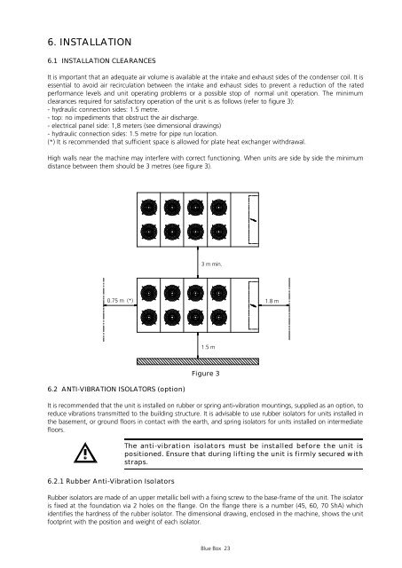
It is important that an adequate air volume is available at the intake and exhaust sides of the condenser coil. It is<br />
essential to avoid air recirculation between the intake and exhaust sides to prevent a reduction of the rated<br />
performance levels and unit operating problems or a possible stop of normal unit operation. The minimum<br />
clearances required for satisfactory operation of the unit is as follows (refer to figure 3):<br />
- hydraulic connection sides: 1.5 metre.<br />
- top: no impediments that obstruct the air discharge.<br />
- electrical panel side: 1,8 meters (see dimensional drawings)<br />
- hydraulic connection sides: 1.5 metre for pipe run location.<br />
(*) It is recommended that sufficient space is allowed for plate heat exchanger withdrawal.<br />
High walls near the machine may interfere with correct functioning. When units are side by side the minimum<br />
distance between them should be 3 metres (see figure 3).<br />
3 m min.<br />
0.75 m (*) 1.8 m<br />
6.2 ANTI-VIBRATION ISOLATORS (option)<br />
1.5 m<br />
Figure 3<br />
It is recommended that the unit is installed on rubber or spring anti-vibration mountings, supplied as an option, to<br />
reduce vibrations transmitted to the building structure. It is advisable to use rubber isolators for units installed in<br />
the basement, or ground floors in contact with the earth, and spring isolators for units installed on intermediate<br />
floors.<br />
6.2.1 Rubber Anti-Vibration Isolators<br />
The anti-vibration isolators must be installed before the unit is<br />
positioned. Ensure that during lifting the unit is firmly secured with<br />
straps.<br />
Rubber isolators are made of an upper metallic bell with a fixing screw to the base-frame of the unit. The isolator<br />
is fixed at the foundation via 2 holes on the flange. On the flange there is a number (45, 60, 70 ShA) which<br />
identifies the hardness of the rubber isolator. The dimensional drawing, enclosed in the machine, shows the unit<br />
footprint with the position and weight of each isolator.<br />
Blue Box 23