KAPPA V ECHOS AC IOM.pdf - Industrial Air
KAPPA V ECHOS AC IOM.pdf - Industrial Air
KAPPA V ECHOS AC IOM.pdf - Industrial Air

You also want an ePaper? Increase the reach of your titles
YUMPU automatically turns print PDFs into web optimized ePapers that Google loves.
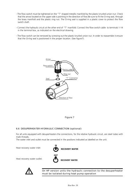
- The flow switch must be tightened on the “T” shaped metallic manifold by the plastic knurled union nut. Check<br />
that the arrow located on the upper side is pointing in the direction of flow.Be sure to fit the O-ring seal, through<br />
the brass manifold and the plastic ring nut. The O-ring seal is supplied in a plastic cover to protect the flow<br />
switch shaft.<br />
- Connect the hydraulic circuit at the other end of “T” manifold. Connect the flow switch cable to terminals 1-14<br />
in the terminal box, as indicated on the electrical drawing.<br />
- The flow switch can be removed by screwing out the plastic knurled union nut. In order to reassemble it ensure<br />
that the O-ring seal is positioned in the proper location. (See figure7).<br />
Figure 7<br />
6.6 DESUPERHEATER HYDRAULIC CONNECTION (optional)<br />
For all units equipped with desuperheaters the connections, for the relative hydraulic circuit, are steel tubes with<br />
male threads.<br />
The water inlet and outlet must be connected in the positions indicated as labelled on the unit.<br />
Heat recovery water inlet:<br />
Heat recovery water outlet:<br />
Arrow<br />
Flow switch<br />
Seal<br />
IN<br />
OUT<br />
Electric cable<br />
Ring nut<br />
Direction of flow<br />
DIREZIONE DEL FLUSSO<br />
“T” Connector<br />
RECOVERY WATER<br />
RECOVERY WATER<br />
On HP version units the hydraulic connection to the desuperheater<br />
must be isolated during heat pump operation<br />
Blue Box 29