KAPPA V ECHOS AC IOM.pdf - Industrial Air
KAPPA V ECHOS AC IOM.pdf - Industrial Air
KAPPA V ECHOS AC IOM.pdf - Industrial Air
Create successful ePaper yourself
Turn your PDF publications into a flip-book with our unique Google optimized e-Paper software.
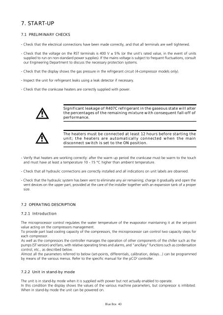
7. START-UP<br />
7.1 PRELIMINARY CHECKS<br />
- Check that the electrical connections have been made correctly, and that all terminals are well tightened.<br />
- Check that the voltage on the RST terminals is 400 V ± 5% (or the unit’s rated value, in the event of units<br />
supplied to run on non-standard power supplies). If the mains voltage is subject to frequent fluctuations, consult<br />
our Engineering Department to discuss the necessary protection systems.<br />
- Check that the display shows the gas pressure in the refrigerant circuit (4-compressor models only).<br />
- Inspect the unit for refrigerant leaks using a leak detector if necessary.<br />
- Check that the crankcase heaters are correctly supplied with power.<br />
7.2 OPERATING DESCRIPTION<br />
7.2.1 Introduction<br />
The microprocessor control regulates the water temperature of the evaporator maintaining it at the set-point<br />
value acting on the compressors management.<br />
To provide part load cooling capacity of the compressors, the microprocessor can control two capacity steps for<br />
each compressor.<br />
As well as the compressors the controller manages the operation of other components of the chiller such as the<br />
pumps (ST version) and fans, with relative operating times and alarms, and “ancillary” functions such as condensation<br />
control, etc., as described below.<br />
Almost all the parameters referred to below (set-points, differentials, calibration, delays...) can be programmed<br />
by means of the various menus. Refer to the specific manual for the pCO 2 controller.<br />
7.2.2 Unit in stand-by mode<br />
Significant leakage of R407C refrigerant in the gaseous state will alter<br />
the percentages of the remaining mixture with consequent fall-off of<br />
performance.<br />
The heaters must be connected at least 12 hours before starting the<br />
unit; the heaters are automatically connected when the main<br />
disconnect switch is set to the ON position.<br />
- Verify that heaters are working correctly: after the warm up period the crankcase must be warm to the touch<br />
and must have at least a temperature 10 - 15 °C higher than ambient temperature.<br />
- Check that all hydraulic connections are correctly installed and all indications on unit labels are observed.<br />
- Check that the hydraulic system has been vent to eliminate any air remaining; charge it gradually and open the<br />
vent devices on the upper part, provided at the care of the installer together with an expansion tank of a proper<br />
size.<br />
The unit is in stand-by mode when it is supplied with power but not actually enabled to operate.<br />
In this condition the display shows the values of the various machine parameters, but compressor is inhibited.<br />
When in stand-by mode the unit can be powered on.<br />
Blue Box 40


