Symmetra PX 250/500 kW 400/480 V - Fusion Power System
Symmetra PX 250/500 kW 400/480 V - Fusion Power System
Symmetra PX 250/500 kW 400/480 V - Fusion Power System

You also want an ePaper? Increase the reach of your titles
YUMPU automatically turns print PDFs into web optimized ePapers that Google loves.
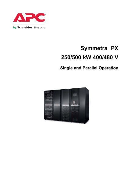
<strong>Symmetra</strong> <strong>PX</strong><br />
<strong>250</strong>/<strong>500</strong> <strong>kW</strong> <strong>400</strong>/<strong>480</strong> V<br />
Single and Parallel Operation
Table of Contents<br />
Overview.............................................................................................................................. 1<br />
Symbols used ............................................................................................................... 3<br />
Parallel <strong>System</strong> Summary.......................................................................................... 3<br />
UPS Summary Screen ................................................................................................ 4<br />
Single <strong>System</strong>............................................................................................................ 4<br />
Parallel <strong>System</strong>.......................................................................................................... 4<br />
Operation Modes ............................................................................................................ 5<br />
UPS Modes .................................................................................................................... 5<br />
Normal Operation ...................................................................................................... 5<br />
Battery operation....................................................................................................... 6<br />
Requested static bypass operation/forced static bypass operation .......................... 7<br />
Battery test ................................................................................................................ 8<br />
<strong>System</strong> Modes .............................................................................................................. 9<br />
On.............................................................................................................................. 9<br />
Off.............................................................................................................................. 9<br />
Requested static bypass operation/forced static bypass operation .......................... 9<br />
Maintenance bypass operation..................................................................................10<br />
Autostart Countdown ................................................................................................11<br />
Operation Procedures .................................................................................................12<br />
Access Screens Protected by User Password ....................................................12<br />
Start Up <strong>System</strong> from Maintenance Bypass Operation.....................................13<br />
Shut Down <strong>System</strong> from Normal to Maintenance Bypass Operation............15<br />
Transfer from Normal to Requested Static Bypass Operation ........................17<br />
Transfer from Requested Static Bypass to Normal Operation ........................18<br />
Isolate this Single UPS from the Parallel <strong>System</strong> ...............................................20<br />
Add UPS to a Running Parallel <strong>System</strong> .................................................................21<br />
Access a Configured Network Management Card ..............................................23<br />
Operate the APC Battery Breaker Manually..........................................................24<br />
Configuration....................................................................................................................25<br />
Access the User Configuration Screen..................................................................25<br />
Perform a Battery Runtime Calibration..................................................................26<br />
990–2748E-001 <strong>Symmetra</strong> <strong>PX</strong> <strong>250</strong>/<strong>500</strong> <strong>kW</strong> <strong>400</strong>/<strong>480</strong> V i
Set the Battery Test Settings ....................................................................................26<br />
Set the Display Settings.............................................................................................28<br />
Set the Network Management Card (NMC) Settings...........................................29<br />
Set the User Password Settings ..............................................................................30<br />
Set the Alarm Settings................................................................................................31<br />
Set the <strong>System</strong> Time ...................................................................................................33<br />
Set the Language and Regional Settings ..............................................................34<br />
Maintenance ......................................................................................................................36<br />
Access Predictive Maintenance Screen ................................................................36<br />
Determine if you need a Replacement Part ..........................................................37<br />
Return Parts to APC ....................................................................................................38<br />
User-Replaceable Parts..............................................................................................38<br />
Battery Module Replacement....................................................................................38<br />
Directions for Replacement .......................................................................................38<br />
Directions for Storage ...............................................................................................39<br />
Replace Batteries.......................................................................................................40<br />
Replace <strong>Power</strong> Modules.............................................................................................40<br />
Replace Intelligence Modules...................................................................................42<br />
Replace Boards in Input/Output/Bypass Enclosure...........................................43<br />
Replace Boards in the Battery Enclosure .............................................................44<br />
Troubleshooting..............................................................................................................45<br />
Alarms.............................................................................................................................45<br />
Alarm Button .............................................................................................................45<br />
Alarm Levels..............................................................................................................45<br />
View the Active Alarms...............................................................................................46<br />
View the Event Log......................................................................................................47<br />
Bookmark an Entry in the Event Log......................................................................50<br />
View and Save Information about Firmware Version .........................................51<br />
Reboot the Display ......................................................................................................53<br />
ii <strong>Symmetra</strong> <strong>PX</strong> <strong>250</strong>/<strong>500</strong> <strong>kW</strong> <strong>400</strong>/<strong>480</strong> V 990–2748E-001
Overview<br />
Display Overview<br />
Note: The screens shown in this manuals are examples only.<br />
The UPS graphical user interface is located in<br />
the Input/Output/Bypass Enclosure. The UPS<br />
utilizes the touch-screen display to configure and<br />
monitor the system, and provides the user with<br />
visible and audible alarms.<br />
The screens are organized hierarchically. In<br />
parallel systems the Parallel <strong>System</strong> Summary<br />
screen is at the top of the hierarchy. In single<br />
systems the UPS Summary screen is at the top of<br />
the hierarchy.<br />
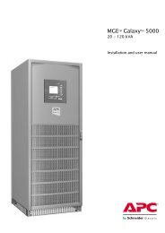
Overview of Breakers in the MBwD (Option)<br />
Note: The MBwD is only applicable for single systems.<br />
The APC MBwD contains the breakers Q1, Q2,<br />
Q3, and Q5. When the associated breaker lamp<br />
is lit, it is ok to open and close the breaker.<br />
To Distribution Breakers<br />
990–2748E-001 <strong>Symmetra</strong> <strong>PX</strong> <strong>250</strong>/<strong>500</strong> <strong>kW</strong> <strong>400</strong>/<strong>480</strong> V 1
Navigation<br />
Parallel <strong>System</strong><br />
Summary<br />
Parallel Input<br />
Summary<br />
Parallel Bypass<br />
Summary<br />
Parallel Output<br />
Summary<br />
UPS <strong>System</strong><br />
UPS Summary<br />
UPS Input<br />
Summary<br />
UPS Bypass<br />
Summary<br />
UPS Battery<br />
Summary<br />
<strong>System</strong> Status<br />
Subfeed Summary<br />
UPS Output<br />
Summary<br />
UPS <strong>System</strong><br />
<strong>System</strong> Information<br />
Configuration<br />
Operation<br />
Language Settings<br />
<strong>System</strong> Status<br />
Event Log<br />
Firmware Overview<br />
Predictive<br />
Maintenance<br />
User Configuration<br />
Service<br />
Configuration<br />
Factory<br />
Configuration<br />
Start-Up<br />
Shutdown<br />
Transfer to normal<br />
operation<br />
Transfer to static<br />
bypass<br />
Isolate this UPS<br />
Regional Settings<br />
2 <strong>Symmetra</strong> <strong>PX</strong> <strong>250</strong>/<strong>500</strong> <strong>kW</strong> <strong>400</strong>/<strong>480</strong> V 990–2748E-001
Symbols used<br />
WARNING: Indicates an electrical hazard, which, if not avoided, could result in<br />
injury or death.<br />
Caution: Indicates a hazard, which, if not avoided, could result in injury or death.<br />
Note: Indicates important information.<br />
See: Indicates that more information is available on this subject.<br />
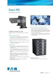
Parallel <strong>System</strong> Summary<br />
The Parallel <strong>System</strong> Summary screen is the home screen in parallel systems. It provides you with an<br />
overview of the parallel system and circuit breakers. It shows the system status and the power flow<br />
through the system and gives access to the system’s summary screens.<br />
Note: The operated UPS is highlighted on the screen and the other UPS units are faded.<br />
A. Access further details on the current<br />
screen.<br />
B. Go to the UPS <strong>System</strong> screen.<br />
C. Go to the Parallel Input Summary screens.<br />
D. Go to the Parallel Bypass Summary<br />
screens.<br />
E. Go to the Parallel Output Summary<br />
screens.<br />
F. Go to the UPS Summary screens.<br />
990–2748E-001 <strong>Symmetra</strong> <strong>PX</strong> <strong>250</strong>/<strong>500</strong> <strong>kW</strong> <strong>400</strong>/<strong>480</strong> V 3
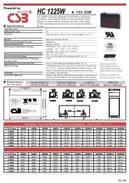
UPS Summary Screen<br />
Single <strong>System</strong><br />
In single systems, the UPS Summary screen is the home screen. It provides you with an overview of<br />
the UPS system and circuit breakers. It shows the system status and the power flow through the system<br />
and gives access to the system’s summary screens and the UPS <strong>System</strong> screen.<br />
A. Access further details on the current<br />
screen.<br />
B. Go to the UPS <strong>System</strong> screen.<br />
C. Go to the <strong>System</strong> Status screen for the<br />
current UPS.<br />
D. Go to the Bypass Summary screens.<br />
E. Go to the Input Summary screens.<br />
F. Go to the Output Summary screens.<br />
G. Go to the Battery Summary screens.<br />
H. Log out of password protected screens.<br />
Parallel <strong>System</strong><br />
In parallel systems, the UPS Summary screen provides you with an overview of the actual UPS and<br />
circuit breakers. It shows the system status and the power flow through the UPS and gives access to the<br />
system’s summary screens and the UPS <strong>System</strong> screen.<br />
A. Access further details on the current<br />
screen.<br />
B. Go to the UPS <strong>System</strong> screen.<br />
C. Go to the <strong>System</strong> Status screen for the<br />
current UPS.<br />
D. Go to the Bypass Summary screens.<br />
E. Go to the Input Summary screens.<br />
F. Go to the Output Summary screens.<br />
G. Go to the Battery Summary screens.<br />
H. Go to the Parallel <strong>System</strong> Summary screen.<br />
I. Go to the previous screen.<br />
J. Log out of password protected screens.<br />
4 <strong>Symmetra</strong> <strong>PX</strong> <strong>250</strong>/<strong>500</strong> <strong>kW</strong> <strong>400</strong>/<strong>480</strong> V 990–2748E-001
Operation Modes<br />
UPS Modes<br />
The UPS operation mode is indicated in the top right corner of the screen under the heading UPS<br />
Mode. The UPS mode indicates the current status of the operated UPS.<br />
Normal Operation<br />
During normal operation, the UPS supports the critical load with conditioned power. While the UPS is<br />
operating in normal operation, a single-line diagram will appear on the screen. A green line indicates<br />
the power flow from the utility/mains, through the UPS system, and to the load. The green line to the<br />
batteries indicates that the batteries are connected.<br />
Single <strong>System</strong> Parallel <strong>System</strong><br />
990–2748E-001 <strong>Symmetra</strong> <strong>PX</strong> <strong>250</strong>/<strong>500</strong> <strong>kW</strong> <strong>400</strong>/<strong>480</strong> V 5<br />
or
Battery operation<br />
If the utility/mains supply fails, the UPS transfers to battery operation. During battery operation,<br />
battery power ensures uninterrupted support to the critical load. While the UPS system is in battery<br />
operation, a single-line diagram will appear on the screen. The green line indicates the power flow<br />
from the batteries, through the inverters, and then to the load.<br />
Single <strong>System</strong> Parallel <strong>System</strong><br />
6 <strong>Symmetra</strong> <strong>PX</strong> <strong>250</strong>/<strong>500</strong> <strong>kW</strong> <strong>400</strong>/<strong>480</strong> V 990–2748E-001<br />
or
Requested static bypass operation/forced static bypass operation<br />
The UPS is in requested static bypass following a command from the graphical user interface. And<br />
the UPS is in forced bypass when a fault on the system has caused static bypass operation. During<br />
static bypass operation, the critical load is supplied directly by utility/mains power. While the UPS is<br />
operating in this mode, a single-line diagram will appear on the screen. The orange line indicates the<br />
power flow from the utility/mains through the bypass static switch, and then to the critical load.<br />
Note: The batteries are not available as an alternate power source while the system is<br />
in forced static bypass operation. The batteries are available in requested bypass, and<br />
it is possible to manually transfer to normal operation. If there is an interruption to the<br />
utility/mains power supply during requested static bypass operation, the system will<br />
transfer to battery operation. This will cause an interruption to the power supplying the<br />
load and may result in a load drop.<br />
Single <strong>System</strong> Parallel <strong>System</strong><br />
990–2748E-001 <strong>Symmetra</strong> <strong>PX</strong> <strong>250</strong>/<strong>500</strong> <strong>kW</strong> <strong>400</strong>/<strong>480</strong> V 7<br />
or
Battery test<br />
The UPS is in battery test mode when the UPS is performing a battery self-test. During battery test,<br />
the battery runtime capacity is reduced by 10%.<br />
Note: The battery test will stop if the mains supply fails during the test.<br />
Single <strong>System</strong> Parallel <strong>System</strong><br />
8 <strong>Symmetra</strong> <strong>PX</strong> <strong>250</strong>/<strong>500</strong> <strong>kW</strong> <strong>400</strong>/<strong>480</strong> V 990–2748E-001<br />
or
<strong>System</strong> Modes<br />
The system mode is indicated in the top right corner of the screen under the heading <strong>System</strong> Mode. The<br />
system mode indicates the current output status of the complete system, and not the individual UPS unit.<br />
On<br />
When the system mode is On, the UPS system supports the critical load with conditioned power. The<br />
load is supported by the UPS in both normal and battery operation.<br />
Off<br />
When the system mode is Off, the UPS system does not support the connected load with power.<br />
Requested static bypass operation/forced static bypass operation<br />
The UPS is in requested static bypass following a command from the graphical user interface. And<br />
the UPS is in forced bypass when a fault on the system has caused static bypass operation. During<br />
static bypass operation, the critical load is supplied directly by utility/mains power. While the UPS is<br />
operating in this mode, a single-line diagram will appear on the screen. The orange line indicates the<br />
power flow from the utility/mains through the bypass static switch, and then to the critical load.<br />
990–2748E-001 <strong>Symmetra</strong> <strong>PX</strong> <strong>250</strong>/<strong>500</strong> <strong>kW</strong> <strong>400</strong>/<strong>480</strong> V 9
Maintenance bypass operation<br />
During maintenance bypass operation, the critical load is supplied directly by utility/mains power.<br />
While the UPS system is in maintenance bypass operation, a single-line diagram will appear on<br />
the screen. The orange line indicates the power flow from the utility/mains, and then to the critical<br />
load via the Q3 switch.<br />
Note: The batteries are not available as an alternate power source while the UPS system<br />
is in maintenance bypass operation.<br />
Single <strong>System</strong> Parallel <strong>System</strong><br />
10 <strong>Symmetra</strong> <strong>PX</strong> <strong>250</strong>/<strong>500</strong> <strong>kW</strong> <strong>400</strong>/<strong>480</strong> V 990–2748E-001<br />
or
Autostart Countdown<br />
The system can be set up for an automatic start when AC utility power is restored following a low<br />
battery voltage shutdown. The autostart countdown window is shown over all screens until the<br />
countdown period expires or the autostart is manually stopped by pressing the stop button.<br />
This feature is disabled by default and is not supported in parallel systems. Contact APC if this<br />
feature should be enabled.<br />
990–2748E-001 <strong>Symmetra</strong> <strong>PX</strong> <strong>250</strong>/<strong>500</strong> <strong>kW</strong> <strong>400</strong>/<strong>480</strong> V 11
Operation Procedures<br />
Access Screens Protected by User Password<br />
1. When prompted for the user-password, press the password field to access the keyboard.<br />
2. Type in the user password and press Enter.<br />
Note: On installation, the user password is set to “apc”.<br />
12 <strong>Symmetra</strong> <strong>PX</strong> <strong>250</strong>/<strong>500</strong> <strong>kW</strong> <strong>400</strong>/<strong>480</strong> V 990–2748E-001
Start Up <strong>System</strong> from Maintenance Bypass Operation<br />
Note: Start-up condition: The load is supplied via the Q3 switch from the utility/mains,<br />
and the other breakers are open.<br />
1. Close the UPS input breaker (Q1). This will power up the UPS display.<br />
2. Press the UPS <strong>System</strong> button in the bottom left corner to access the UPS <strong>System</strong> screen.<br />
Single <strong>System</strong> Parallel <strong>System</strong><br />
3. Press the Operation button. Type in the user password and complete with Enter.<br />
4. Press <strong>System</strong> Start-up button.<br />
Single <strong>System</strong> Parallel <strong>System</strong><br />
990–2748E-001 <strong>Symmetra</strong> <strong>PX</strong> <strong>250</strong>/<strong>500</strong> <strong>kW</strong> <strong>400</strong>/<strong>480</strong> V 13
5. Follow the steps which appear on the screen. Steps will appear in the order in which they<br />
need to be completed. A step will initially appear in red and then when it is completed, the<br />
step will change to green. The next step to be completed will be highlighted in red text and<br />
yellow background.<br />
Note: Grey buttons are touch-screen functions.<br />
Single <strong>System</strong> Parallel <strong>System</strong><br />
6. Check that the UPS Mode is Normal Operation in the upper right corner.<br />
14 <strong>Symmetra</strong> <strong>PX</strong> <strong>250</strong>/<strong>500</strong> <strong>kW</strong> <strong>400</strong>/<strong>480</strong> V 990–2748E-001
Shut Down <strong>System</strong> from Normal to Maintenance<br />
Bypass Operation<br />
Note: Press the home button to go to the UPS Summary or Parallel <strong>System</strong> Summary<br />
screen.<br />
1. Press the UPS <strong>System</strong> button in the bottom left corner to access the UPS <strong>System</strong> screen.<br />
Single <strong>System</strong> Parallel <strong>System</strong><br />
2. Press the Operation button. Type in the user password and complete with Enter.<br />
3. Press the <strong>System</strong> Shutdown button on the Operation screen.<br />
Single <strong>System</strong> Parallel <strong>System</strong><br />
990–2748E-001 <strong>Symmetra</strong> <strong>PX</strong> <strong>250</strong>/<strong>500</strong> <strong>kW</strong> <strong>400</strong>/<strong>480</strong> V 15
4. Follow the steps which appear on the screen. Steps will appear in the order in which they<br />
need to be completed. A step will initially appear in red and then when it is completed, the<br />
step will change to green. The next step to be completed will be highlighted in red text and<br />
yellow background.<br />
Note: Grey buttons are touch-screen functions.<br />
Single <strong>System</strong> Parallel <strong>System</strong><br />
Note: The display will turn off when the UPS input breaker (Q1) is opened.<br />
Caution: Do not open the Q3 breaker when the system is in maintenance bypass<br />
operation, as it may result in a load drop.<br />
16 <strong>Symmetra</strong> <strong>PX</strong> <strong>250</strong>/<strong>500</strong> <strong>kW</strong> <strong>400</strong>/<strong>480</strong> V 990–2748E-001
Transfer from Normal to Requested Static Bypass<br />
Operation<br />
Note: Following this procedure will transfer the entire parallel system to requested<br />
static bypass.<br />
Note: Press the home button to go to the UPS Summary or Parallel <strong>System</strong> Summary<br />
screen.<br />
1. Press the UPS system button in the bottom left corner to access the UPS <strong>System</strong> screen.<br />
Single <strong>System</strong> Parallel <strong>System</strong><br />
2. Press the Operation button. Type in the user password and complete with Enter.<br />
990–2748E-001 <strong>Symmetra</strong> <strong>PX</strong> <strong>250</strong>/<strong>500</strong> <strong>kW</strong> <strong>400</strong>/<strong>480</strong> V 17
3. Press the Normal Op. → Static Bypass button.<br />
Single <strong>System</strong> Parallel <strong>System</strong><br />
4. Press the Initiate Transfer button to go to static bypass operation. The Initiate Transfer button<br />
is greyed out when the transfer is not available.<br />
5. Check that the status has changed to Requested Static Bypass in the upper right corner.<br />
Transfer from Requested Static Bypass to Normal<br />
Operation<br />
Note: Following this procedure will transfer the entire parallel system from requested<br />
static bypass to normal operation.<br />
Note: Press the home button to go to the UPS Summary or Parallel <strong>System</strong> Summary<br />
screen.<br />
18 <strong>Symmetra</strong> <strong>PX</strong> <strong>250</strong>/<strong>500</strong> <strong>kW</strong> <strong>400</strong>/<strong>480</strong> V 990–2748E-001
1. Press the UPS <strong>System</strong> button in the bottom left corner to access the UPS <strong>System</strong> screen.<br />
Single <strong>System</strong> Parallel <strong>System</strong><br />
2. Press the Operation button. Type in the user password and complete with Enter.<br />
3. Press the Static Bypass -> Normal Op. button on the Operation screen.<br />
Single <strong>System</strong> Parallel <strong>System</strong><br />
4. Press the Initiate Transfer button to go to normal operation. The Initiate Transfer button<br />
is greyed out when transfer is not available.<br />
5. Check that the status has changed to Normal Operation in the upper right corner.<br />
990–2748E-001 <strong>Symmetra</strong> <strong>PX</strong> <strong>250</strong>/<strong>500</strong> <strong>kW</strong> <strong>400</strong>/<strong>480</strong> V 19
Isolate this Single UPS from the Parallel <strong>System</strong><br />
Note: Before you start this procedure, ensure that the remaining UPS units can supply<br />
the load.<br />
Note: This procedure is only applicable to parallel systems.<br />
Note: Press the home button to go to the Parallel <strong>System</strong> Summary screen.<br />
1. Press the UPS <strong>System</strong> button in the bottom left corner to access the UPS <strong>System</strong> screen.<br />
2. Press the Operation button. Type in the user password and complete with Enter.<br />
20 <strong>Symmetra</strong> <strong>PX</strong> <strong>250</strong>/<strong>500</strong> <strong>kW</strong> <strong>400</strong>/<strong>480</strong> V 990–2748E-001
3. Press the Isolate this UPS button on the Operation screen.<br />
4. Follow the steps which appear on the screen. Steps will appear in the order in which they<br />
need to be completed. A step will initially appear in red and then when it is completed, the<br />
step will change to green. The next step to be completed will be highlighted in red text and<br />
yellow background.<br />
Note: Grey buttons are touch-screen functions.<br />
Note: The display will turn off when the UPS input breaker (Q1) is opened.<br />
Add UPS to a Running Parallel <strong>System</strong><br />
1. Close the UPS input breaker (Q1). This will power up the UPS display.<br />
2. When the screen becomes active, verify that all UPS is set up as a parallel system and that<br />
all units are shown on the screen.<br />
990–2748E-001 <strong>Symmetra</strong> <strong>PX</strong> <strong>250</strong>/<strong>500</strong> <strong>kW</strong> <strong>400</strong>/<strong>480</strong> V 21
3. Press the UPS <strong>System</strong> button in the bottom left corner to access the UPS <strong>System</strong> screen.<br />
4. Press the Operation button. Type in the user password and complete with Enter.<br />
5. Press <strong>System</strong> Start-up button.<br />
22 <strong>Symmetra</strong> <strong>PX</strong> <strong>250</strong>/<strong>500</strong> <strong>kW</strong> <strong>400</strong>/<strong>480</strong> V 990–2748E-001
6. Follow the steps which appear on the screen. Steps will appear in the order in which they<br />
need to be completed. A step will initially appear in red and then when it is completed, the<br />
step will change to green. The next step to be completed will be highlighted in red text and<br />
yellow background.<br />
7. Check that the UPS Mode has changed to Normal Operation in the upper right corner.<br />
Access a Configured Network Management Card<br />
Note: The below procedure shows how to access the Network Management Card from<br />
a web interface. It is also possible to use the following interfaces: Telnet and SSH,<br />
SNMP, FTP, and SCP. See the Network Management Card Installation Manual for<br />
more information.<br />
Note: Ensure that only one NMC in the entire system is set to synchronize time.<br />
Use Microsoft Internet Explorer ® (IE) 7.x or higher (on Windows operating systems only) or Mozilla ®<br />
Firefox ® 3.0.6 or higher (on all operating systems) to access the Web interface of the Network<br />
Management Card. Other commonly available browsers may work but have not been fully tested by<br />
APC.<br />
You can use either of the following protocols when you use the Web interface:<br />
• The HTTP protocol (enabled by default), which provides authentication by user name and password<br />
but no encryption.<br />
• The HTTPS protocol, which provides extra security through Secure Socket Layer (SSL); encrypts<br />
user names, passwords, and data being transmitted; and authenticates Network Management Cards<br />
by means of digital certificates.<br />
To access the Web interface and configure the security of your device on the network:<br />
1. Address the Network Management Card by its IP address (or its DNS name, if a DNS name<br />
is configured).<br />
2. Enter the user name and password (by default, “apc” and “apc” for an Administrator).<br />
3. To enable or disable the HTTP or HTTPS protocol, use the Network menu on the<br />
Administration tab, and select the Access option under the Web heading on the left navigation<br />
menu.<br />
990–2748E-001 <strong>Symmetra</strong> <strong>PX</strong> <strong>250</strong>/<strong>500</strong> <strong>kW</strong> <strong>400</strong>/<strong>480</strong> V 23
See: See the Security Handbook, available on the APC Network Management Card<br />
Utility CD or from the APC Web site, www.apc.com, for more information on selecting<br />
and configuring network security.<br />
Operate the APC Battery Breaker Manually<br />
1. Turn the selector to Manual position.<br />
2. Check the spring status:<br />
a If CHARGED SPRING, go to step 3.<br />
b If DISCHARGED, charge the spring by pressing the bottom part of the handle to release it<br />
and pumping the handle a few times until the spring status says CHARGED SPRING.<br />
3. Push the green ON button to turn the breaker on. A red ON indication will show the breaker<br />
status.<br />
24 <strong>Symmetra</strong> <strong>PX</strong> <strong>250</strong>/<strong>500</strong> <strong>kW</strong> <strong>400</strong>/<strong>480</strong> V 990–2748E-001
Configuration<br />
Access the User Configuration Screen<br />
The UPS system is configured from the password-protected user configuration area of the display.<br />
1. Press the UPS system button in the bottom left corner to access the UPS <strong>System</strong> screen<br />
Single <strong>System</strong> Parallel <strong>System</strong><br />
2. Press the Configuration button to access the Configuration screen.<br />
3. Press the User Configuration button on the Configuration screen.<br />
990–2748E-001 <strong>Symmetra</strong> <strong>PX</strong> <strong>250</strong>/<strong>500</strong> <strong>kW</strong> <strong>400</strong>/<strong>480</strong> V 25
Perform a Battery Runtime Calibration<br />
Recalibrating the batteries keeps measurements like runtime and battery charge accurate.<br />
1. Go to the User Configuration screen by following the steps in “Access the User Configuration<br />
Screen“.<br />
2. Press the Battery Test Settings button on the User Configuration screen to access the Battery<br />
Test Settings screen.<br />
3. Press Start to begin the battery runtime calibration. The batteries must be 100% charged to start<br />
a calibration. You can press Cancel to stop the calibration. The status of the runtime calibration<br />
is shown under Runtime calibration status.<br />
Set the Battery Test Settings<br />
The battery self-test simulates the battery mode of operation. If AC utility/mains power fails during the<br />
test, the test stops and the UPS supplies battery power.<br />
The test detects any weak or defective battery cells. To do this, the load must be high enough to draw<br />
sufficient current which in turn causes the voltage to drop to a low level.<br />
The following criteria should be met to ensure your search detects any weak battery cells:<br />
• The total discharge current to the load from both the positive and negative sides of the batteries<br />
needs to be at least half of the rated battery Ah, which is determined by the number of installed<br />
battery strings. For example, if you have 18 Ah of batteries, more than 9 A must be drawn by the<br />
load from each battery side.<br />
• Both the positive and negative battery voltage must be lower than 280 V for longer than 16 seconds.<br />
26 <strong>Symmetra</strong> <strong>PX</strong> <strong>250</strong>/<strong>500</strong> <strong>kW</strong> <strong>400</strong>/<strong>480</strong> V 990–2748E-001
The test lasts for approximately 10% of the available runtime.<br />
1. Go to the User Configuration screen by following the steps in “Access the User Configuration<br />
Screen“.<br />
2. Press the Battery Test Settings button on the User Configuration screen to access the Battery<br />
Test Settings screen.<br />
3. Set the battery test settings<br />
a Battery self-test: Press Start to begin the battery self-test immediately. You can press Cancel<br />
to stop the self-test and continue in normal operation. The status of the self-test is shown<br />
under Self-test information.<br />
b Auto battery self-test every n weeks: Select the time in weeks between automatic battery<br />
self-tests. APC recommends a battery self test every 12 weeks.<br />
c Auto battery self-test start time (HH:mm:ss): Select the time of the day the battery self-test<br />
must start.<br />
d Auto battery self-test day of week: Select the day of the week the battery self-test must start.<br />
e Reset battery test alarms: Press the Reset button to reset the battery alarms.<br />
4. Press Apply to confirm the settings.<br />
990–2748E-001 <strong>Symmetra</strong> <strong>PX</strong> <strong>250</strong>/<strong>500</strong> <strong>kW</strong> <strong>400</strong>/<strong>480</strong> V 27
Set the Display Settings<br />
1. Go to the User Configuration screen by following the steps in “Access the User Configuration<br />
Screen“.<br />
2. Press the Display Settings button on the User Configuration screen to access the Display<br />
Settings screen.<br />
3. Set the display settings:<br />
a Brightness: Place the finger on the indicator and slide it left or right to the desired setting.<br />
b Temperature unit: Select C for Centigrade or F for Fahrenheit.<br />
c Back light time out: Select the time limit for turning off the screen back light.<br />
d Date format: Select the preferred setting.<br />
e Waveform voltage label: Select phase-to-phase or phase-to-neutral.<br />
f Recalibrate touch screen: Press the Start button to initiate the calibration of the screen. Press<br />
the points that are shown on the screen to calibrate the touch area of the display.<br />
g Enable audible buttons: Enable or disable audible buttons.<br />
h Enable audible alarms: Enable or disable audible alarms.<br />
i Enable APC Q breaker prefix: Enable or disable the display of the APC Q breaker prefix<br />
before the breaker name e.g. Q1 for the main input breaker.<br />
28 <strong>Symmetra</strong> <strong>PX</strong> <strong>250</strong>/<strong>500</strong> <strong>kW</strong> <strong>400</strong>/<strong>480</strong> V 990–2748E-001
Set the Network Management Card (NMC) Settings<br />
1. Go to the User Configuration screen by following the steps in “Access the User Configuration<br />
Screen“.<br />
2. Press the NMC Settings button on the User Configuration screen to access the NMC Settings<br />
screen.<br />
3. The NMC Settings screen displays the configuration for each NMC in the system. Press the<br />
Configure NMC Settings button to access the Configure NMC Settings screen and to change<br />
the settings.<br />
4. Change the NMC settings. The IP address, Subnet mask, and Gateway can only be edited if the<br />
NMC is set to manual. See NMC documentation for more information.<br />
a UPS configuration access: Set the UPS access level for the specific NMC. It can be set to<br />
No access, Read, or Read/Write.<br />
990–2748E-001 <strong>Symmetra</strong> <strong>PX</strong> <strong>250</strong>/<strong>500</strong> <strong>kW</strong> <strong>400</strong>/<strong>480</strong> V 29
Network settings mode: Select to use DHCP, BOOTP, or manual IP address.<br />
c IP address: Enter a valid IP address for the card. Only visible if manual mode has been<br />
selected.<br />
d Subnet mask: Enter a valid subnet mask. Only visible if manual mode has been selected.<br />
e Gateway: Enter a valid gateway. Only visible if manual mode has been selected.<br />
5. Press the arrow down button and change the settings.<br />
a Select the Enable Modbus RTU box to enable the use of Modbus RTU.<br />
b Specify the BMS address of the NMC device. Only a BMS Manager should modify this<br />
address.<br />
c Specify the Baud rate of the modbus communication port.<br />
d Specify the Parity of the modbus communication port.<br />
6. Press Apply to confirm the settings.<br />
Set the User Password Settings<br />
1. Go to the User Configuration screen by following the steps in “Access the User Configuration<br />
Screen“.<br />
2. Press the Password Settings button on the User Configuration screen to access the Password<br />
Settings screen.<br />
30 <strong>Symmetra</strong> <strong>PX</strong> <strong>250</strong>/<strong>500</strong> <strong>kW</strong> <strong>400</strong>/<strong>480</strong> V 990–2748E-001
3. Change the user password:<br />
a Press the Enter current password field and type the current password by using the keyboard<br />
on the screen. Complete with Enter.<br />
b Press the Enter new password field and type the new password by using the keyboard on<br />
the screen. Complete with Enter.<br />
c Press the Confirm new password field and re-type the new password. Confirm with Enter.<br />
4. Press Apply to complete the password change procedure.<br />
Set the Alarm Settings<br />
1. Go to the User Configuration screen by following the steps in “Access the User Configuration<br />
Screen“.<br />
2. Press the Alarm Settings button on the User Configuration screen to access the Alarm Settings<br />
screen(s).<br />
990–2748E-001 <strong>Symmetra</strong> <strong>PX</strong> <strong>250</strong>/<strong>500</strong> <strong>kW</strong> <strong>400</strong>/<strong>480</strong> V 31
3. Set the threshold values that must trigger the alarms:<br />
Note: For parallel systems, shared settings are marked with *.<br />
Single <strong>System</strong> Parallel <strong>System</strong><br />
a UPS module redundancy: Set the system threshold for generating alarms in the redundant<br />
power modules. N+0 indicates that the redundancy alarm is disabled. N+1 indicates that<br />
there must be one redundant power module.<br />
b Parallel system redundancy: Set the number of redundant UPS units in a parallel system. If<br />
you have a parallel system with UPS redundancy, you can use this field to configure an alarm<br />
to generate when the load in your parallel system starts using some of the UPS redundant<br />
power. N+0 indicates that there is no redundant power and N+1 indicates that there is one<br />
UPS of redundant power.<br />
c Load alarm threshold (%): Set the threshold for load percentage of the total UPS capacity<br />
for generating an alarm.<br />
d Low battery alarm threshold (seconds): Set the remaining battery runtime threshold for<br />
generating an alarm.<br />
4. Press Apply to confirm the settings and press arrow down to go to the next Alarm Settings<br />
screen.<br />
5. This screen is only visible if subfeed breakers are present. Set the load percentage for each<br />
subfeed breaker that should generate a critical alarm.<br />
6. Press Apply to confirm the settings and press arrow down to go to the next Alarm Settings<br />
screen.<br />
32 <strong>Symmetra</strong> <strong>PX</strong> <strong>250</strong>/<strong>500</strong> <strong>kW</strong> <strong>400</strong>/<strong>480</strong> V 990–2748E-001
7. This screen is only visible if subfeed breakers are present. Set the load percentage for each<br />
subfeed breaker that should generate a warning alarm.<br />
8. Press Apply to confirm the settings.<br />
Set the <strong>System</strong> Time<br />
Note: The date and time will be synchronized between the UPS units in a parallel system.<br />
1. Go to the User Configuration screen by following the steps in “Access the User Configuration<br />
Screen“.<br />
2. Press the <strong>System</strong> Time Settings button on the User Configuration screen to access the <strong>System</strong><br />
Time Settings screen. The <strong>System</strong> Time Settings screen can also be accessed by pressing on the<br />
time displayed in the top right corner of the screen.<br />
990–2748E-001 <strong>Symmetra</strong> <strong>PX</strong> <strong>250</strong>/<strong>500</strong> <strong>kW</strong> <strong>400</strong>/<strong>480</strong> V 33
3. Set the system date and the system time.<br />
4. Press Apply to confirm the settings.<br />
Set the Language and Regional Settings<br />
Note: Press the home button to go to the UPS Summary or Parallel <strong>System</strong> Summary<br />
screen.<br />
1. Press the UPS system button in the bottom left corner to access the UPS <strong>System</strong> screen<br />
Single <strong>System</strong> Parallel <strong>System</strong><br />
2. Press the Language button to access the Language Settings screen.<br />
34 <strong>Symmetra</strong> <strong>PX</strong> <strong>250</strong>/<strong>500</strong> <strong>kW</strong> <strong>400</strong>/<strong>480</strong> V 990–2748E-001
3. Select the preferred language.<br />
4. Select your preferred date format and temperature unit and complete with Finish.<br />
990–2748E-001 <strong>Symmetra</strong> <strong>PX</strong> <strong>250</strong>/<strong>500</strong> <strong>kW</strong> <strong>400</strong>/<strong>480</strong> V 35
Maintenance<br />
Access Predictive Maintenance Screen<br />
Note: Press the home button to go to the UPS Summary or Parallel <strong>System</strong> Summary<br />
screen.<br />
1. Press the UPS <strong>System</strong> button in the bottom left corner to access the UPS <strong>System</strong> screen.<br />
Single <strong>System</strong> Parallel <strong>System</strong><br />
2. Press the <strong>System</strong> Information button on the UPS <strong>System</strong> screen.<br />
36 <strong>Symmetra</strong> <strong>PX</strong> <strong>250</strong>/<strong>500</strong> <strong>kW</strong> <strong>400</strong>/<strong>480</strong> V 990–2748E-001
3. Press the Predictive Maintenance button to access the Predictive Maintenance screen.<br />
4. The Predictive Maintenance screen shows the status and the estimated remaining lifetime of the<br />
power modules and their fans. The status can be OK, Near end, or Exceeded. Remember to<br />
order new spare parts or schedule a maintenance visit when the status is Near end.<br />
Determine if you need a Replacement Part<br />
To determine if you need a replacement part, contact APC Customer Support and follow the procedure<br />
below so that the APC Customer Support representative can assist you promptly:<br />
1. In the event of a module failure, the display interface will indicate an alarm condition. Scroll<br />
through the alarm lists, record the information, and provide it to the representative.<br />
2. Write down the serial number of the unit so that you will have it easily accessible when you<br />
contact APC Customer Support.<br />
3. If possible, call APC Customer Support from a telephone that is within reach of the UPS display<br />
interface so that you can gather and report additional information to the representative.<br />
4. Be prepared to provide a detailed description of the problem. A representative will help you<br />
solve the problem over the telephone, if possible, or will assign a return material authorization<br />
(RMA) number to you. If a module is returned to APC, this RMA number must be clearly<br />
printed on the outside of the package.<br />
5. If the unit is within the warranty period, repairs or replacements will be performed free of<br />
charge. If it is not within the warranty period, there will be a charge.<br />
6. If the unit is covered by an APC service contract, have the contract available to provide<br />
information to the representative.<br />
990–2748E-001 <strong>Symmetra</strong> <strong>PX</strong> <strong>250</strong>/<strong>500</strong> <strong>kW</strong> <strong>400</strong>/<strong>480</strong> V 37
Return Parts to APC<br />
Call APC Customer Support to obtain an RMA number.<br />
To return a failed module to APC, pack the module in the original shipping materials, and return it<br />
by insured, prepaid carrier. The APC Customer Support representative will provide the destination<br />
address. If you no longer have the original shipping materials, ask the representative about obtaining a<br />
new set. Pack the module properly to avoid damage in transit. Never use styrofoam beads or other<br />
loose packaging materials when shipping a module. The module may settle in transit and become<br />
damaged. Enclose a letter in the package with your name, RMA number, address, a copy of the sales<br />
receipt, description of the problem, a phone number, and a cheque as payment (if necessary).<br />
User-Replaceable Parts<br />
WARNING: ALL safety instructions in the Safety Sheet (990-2984) shall be read,<br />
understood and followed. Failure to do so could result in equipment damage,<br />
serious injury, or death.<br />
Part Part number<br />
Battery module WSYBTU2<br />
<strong>Power</strong> module WSYPM25KD<br />
Intelligence module WSYMIM6<br />
<strong>System</strong> power supply WSYPSU2<br />
External connection board WSYEXCB<br />
ID and relay controller board WSYIDRC<br />
External switch gear board WSYEXSG2<br />
Battery breaker motor PSU WSYBBMOPSU2<br />
Battery monitoring board WSYBMB2<br />
A-Bus communication board WSYBATTCOM<br />
Battery Module Replacement<br />
Directions for Replacement<br />
WARNING: Only trained persons familiar with the construction and operation of<br />
the equipment, as well as the electrical and mechanical hazards involved, may<br />
install and remove system components.<br />
Caution: Wait until the system is ready to be powered up before installing battery<br />
modules in the UPS (the time duration from the battery installation until the UPS is<br />
powered up should not exceed 72 hours or 3 days). Failure to do so can result in a deep<br />
discharge of the batteries and cause permanent damage.<br />
Caution: The batteries must only be replaced with APC high performance battery units.<br />
38 <strong>Symmetra</strong> <strong>PX</strong> <strong>250</strong>/<strong>500</strong> <strong>kW</strong> <strong>400</strong>/<strong>480</strong> V 990–2748E-001
APC recommends that a whole battery module (one row of batteries) is replaced at the same time to<br />
ensure optimal run-time (see Example 1). However it may only be necessary to replace three battery<br />
units at the same time according to Examples 2 and 3 in the table below.<br />
Position A Position B Position C Position D Position E Position F<br />
Example 1 New New New New New New<br />
Example 2 New New New Old Old Old<br />
Example 3 Old Old Old New New New<br />
Directions for Storage<br />
Note: The battery modules must be stored indoors and with their protective packaging<br />
still in place.<br />
Note: Stored batteries should be recharged at regular intervals, depending on the storage<br />
temperature.<br />
Storage Temperature Recharge Interval<br />
-15° to 20°C/5°F to 68°F 9 months<br />
20° to 30°C/68°F to 86°F 6 months<br />
30° to 40°C/86°F to 104°F 3 months<br />
Caution: Do not store the batteries for more than 12 months.<br />
990–2748E-001 <strong>Symmetra</strong> <strong>PX</strong> <strong>250</strong>/<strong>500</strong> <strong>kW</strong> <strong>400</strong>/<strong>480</strong> V 39
Replace Batteries<br />
Use two people to lift components weighing between 18–32 kg (40–70 lbs).<br />
1. Holding the handle, gently lift the battery unit<br />
and pull it halfway out. A lock mechanism<br />
prevents it from being pulled all the way out.<br />
2. Release the lock by pushing the battery unit<br />
upwards and pull the battery unit all the way<br />
out while you continue to support its weight.<br />
3. Carefully guide the new battery unit into the<br />
system.<br />
Replace <strong>Power</strong> Modules<br />
Battery Enclosure<br />
WARNING: Only trained persons familiar with the construction and operation of<br />
the equipment, as well as the electrical and mechanical hazards involved, may<br />
install and remove system components.<br />
WARNING: Before replacing the power modules, ensure that the “UPS system<br />
firmware version” and the “<strong>System</strong> firmware version stored at memory card” are<br />
identical on the <strong>System</strong> Information screen.<br />
Use three people to lift components weighing between 32 - 54 kg (/70 - 120 lbs).<br />
40 <strong>Symmetra</strong> <strong>PX</strong> <strong>250</strong>/<strong>500</strong> <strong>kW</strong> <strong>400</strong>/<strong>480</strong> V 990–2748E-001
1. Identify the faulty power module via the display or the red LED indication in the top right<br />
corner of the power module.<br />
2. Deactivate the power module by turning the locking latch counter-clockwise to the unlocked<br />
position.<br />
3. Unscrew the spring-activated knobs on both sides of the power module.<br />
4. Pull the power module up and out of the enclosure as far as the lock mechanism allows.<br />
5. Release the lock by pressing the black plastic tab on each side of the power module and pull<br />
the power module all the way out.<br />
6. Carefully guide the new power module completely into the system.<br />
7. Secure the spring-activated knobs on both sides of the power module.<br />
8. Wait until the firmware update is complete and ensure that the new power module has the same<br />
firmware version as the other power modules in the UPS system:<br />
a On the UPS Summary or the Parallel <strong>System</strong> Summary screen, press the UPS <strong>System</strong> button<br />
in the bottom left corner.<br />
b Press the <strong>System</strong> Information button on the UPS <strong>System</strong> screen.<br />
c Press the Firmware Overview button to open the Firmware Overview screen.<br />
d Verify that the firmware versions is the same.<br />
990–2748E-001 <strong>Symmetra</strong> <strong>PX</strong> <strong>250</strong>/<strong>500</strong> <strong>kW</strong> <strong>400</strong>/<strong>480</strong> V 41
9. Activate the power module by turning the locking latch clockwise to the locked position. The<br />
LED in the top right corner of the power module will start to flash (green) which indicates<br />
that the power module is initializing and doing a self test. When the self test is complete, the<br />
LED will be constant green.<br />
Replace Intelligence Modules<br />
WARNING: Only trained persons familiar with the construction and operation of<br />
the equipment, as well as the electrical and mechanical hazards involved, may<br />
install and remove system components.<br />
WARNING: Before replacing the intelligence modules, ensure that the “UPS system<br />
firmware version” and the “<strong>System</strong> firmware version stored at memory card” are<br />
identical on the <strong>System</strong> Information screen.<br />
WARNING: Replace only one intelligence module at a time.<br />
1. Identify the faulty intelligence module via the<br />
display or red LED indication.<br />
2. Loosen the two screws in one of the<br />
intelligence modules (one in the top and one<br />
through the disable button at the bottom of the<br />
intelligence module).<br />
3. Press down the disable button to loosen and<br />
deactivate the intelligence module.<br />
4. Carefully insert the new module into the slot.<br />
5. Enable the button to close and activate the<br />
intelligence module and the LED will flash<br />
green. When the initialization is complete the<br />
LED will be solid green.<br />
6. Fasten the two screws to secure the intelligence<br />
module.<br />
Input/Output/Bypass Enclosure<br />
42 <strong>Symmetra</strong> <strong>PX</strong> <strong>250</strong>/<strong>500</strong> <strong>kW</strong> <strong>400</strong>/<strong>480</strong> V 990–2748E-001
Replace Boards in Input/Output/Bypass Enclosure<br />
WARNING: Only trained persons familiar with the construction and operation of<br />
the equipment, as well as the electrical and mechanical hazards involved, may<br />
install and remove system components.<br />
WARNING: Before replacing the boards, ensure that the “UPS system firmware<br />
version” and the “<strong>System</strong> firmware version stored at memory card” are identical on<br />
the <strong>System</strong> Information screen.<br />
WARNING: Replace only one board at a time.<br />
Note: A faulty system power supply can be identified via the display or a flashing red<br />
LED indication.<br />
1. Loosen the two/four screws in the corners of<br />
the board.<br />
a External connection board.<br />
b External switch gear board.<br />
c <strong>System</strong> power supply.<br />
d ID and relay controller.<br />
2. Only applicable to the external connection<br />
board and the ID and relay controller: remove<br />
the cables connected to the board.<br />
3. Carefully pull out the board.<br />
4. Only applicable to ID and relay controller:<br />
take the SD memory card from the old ID<br />
and relay controller and install it in the<br />
replacement ID and relay controller.<br />
5. Carefully insert the new board into the slot.<br />
6. Reconnect the cables removed in step 2.<br />
7. Secure the new board with the two/four<br />
screws.<br />
Input/Output/Bypass Enclosure<br />
990–2748E-001 <strong>Symmetra</strong> <strong>PX</strong> <strong>250</strong>/<strong>500</strong> <strong>kW</strong> <strong>400</strong>/<strong>480</strong> V 43
Replace Boards in the Battery Enclosure<br />
WARNING: Only trained persons familiar with the construction and operation of<br />
the equipment, as well as the electrical and mechanical hazards involved, may<br />
install and remove system components.<br />
WARNING: Replace only one board at a time.<br />
1. Loosen the two/four screws in the corners of<br />
the board.<br />
a Battery motor breaker PSU.<br />
b <strong>System</strong> power supply.<br />
c Top-half battery monitoring board.<br />
d Bottom-half battery monitoring board.<br />
e A-Bus communication board.<br />
2. Only applicable to the A-Bus communication<br />
board: remove the cables connected to the<br />
board.<br />
3. Carefully pull out the board.<br />
4. Carefully insert the new board into the slot.<br />
5. Reconnect the cables removed in step 2.<br />
6. Secure the new board with the two/four<br />
screws.<br />
Battery Enclosure<br />
44 <strong>Symmetra</strong> <strong>PX</strong> <strong>250</strong>/<strong>500</strong> <strong>kW</strong> <strong>400</strong>/<strong>480</strong> V 990–2748E-001
Troubleshooting<br />
Alarms<br />
The color of the top of the screen switches from blue to red and an alarm button is shown when an<br />
alarm situation occurs.<br />
Alarm Button<br />
Press the alarm button to go to the Active Alarms screen that displays all active alarms, along with<br />
a corrective action for addressing each alarm. When you press the alarm button, the alarm will<br />
automatically be silenced.<br />
Alarm Levels<br />
Info<br />
Warning<br />
Informational alarm. No immediate action<br />
required. Check the cause of the alarm as soon<br />
as possible.<br />
The load remains supported, but action must be<br />
taken. Call APC for instructions.<br />
990–2748E-001 <strong>Symmetra</strong> <strong>PX</strong> <strong>250</strong>/<strong>500</strong> <strong>kW</strong> <strong>400</strong>/<strong>480</strong> V 45
Critical<br />
View the Active Alarms<br />
Take immediate action. Call APC for<br />
instructions.<br />
1. Press the Alarm button on the top bar when an alarm situation occurs.<br />
2. A list of the active alarms is shown on the screen. Press the Location button to see the location<br />
of the particular module. Press the Graph button to see voltages and currents at the time the<br />
alarm was generated. The three alarm severity icons display at the top of the screen with<br />
numbers indicating how many times each severity type has occurred. Press on that icon or<br />
number to display the next alarm of that severity type on the screen. When you reach the final<br />
alarm, pressing the icon displays the first one of the same severity.<br />
46 <strong>Symmetra</strong> <strong>PX</strong> <strong>250</strong>/<strong>500</strong> <strong>kW</strong> <strong>400</strong>/<strong>480</strong> V 990–2748E-001
View the Event Log<br />
Note: Press the home button to go to the UPS Summary or Parallel <strong>System</strong> Summary<br />
screen.<br />
The Event Log screen can be accessed either by pressing the Event Log button on the Active Alarms<br />
screen see “View the active alarms” or by following this procedure:<br />
1. Press the UPS system button in the bottom left corner to access the UPS <strong>System</strong> screen.<br />
Single <strong>System</strong> Parallel <strong>System</strong><br />
2. Press the <strong>System</strong> Information button on the UPS <strong>System</strong> screen.<br />
3. Press the Event Logs button on the <strong>System</strong> Information screen.<br />
990–2748E-001 <strong>Symmetra</strong> <strong>PX</strong> <strong>250</strong>/<strong>500</strong> <strong>kW</strong> <strong>400</strong>/<strong>480</strong> V 47
4. Active in control indicates which intelligence module is in control of the system. Press the<br />
Active Event Log button to view the records from the intelligence module in control or press<br />
the RIM Event Log to view the records from the intelligence module that is passive.<br />
5. The Recent Events log contains a detailed record of the 32 latest events. Press the Full Log<br />
button to see the 10000 latest events and access the Save Log button.<br />
6. Press the Filter button to filter the event log or go directly to step 9 to save the event log.<br />
48 <strong>Symmetra</strong> <strong>PX</strong> <strong>250</strong>/<strong>500</strong> <strong>kW</strong> <strong>400</strong>/<strong>480</strong> V 990–2748E-001
7. Select to filter the events by source, location and/or timestamp and press OK.<br />
8. Set your filter parameters and press OK to initiate the filtering.<br />
9. To save the log, insert a USB flash drive into the USB port on the display.<br />
Note: Do not remove the USB flash drive before a dialog box on the display indicates<br />
that it is safe to remove the USB flash drive.<br />
Note: USB flash drives from the following manufacturers have passed our tests: Cn<br />
Memory, SanDisk, Integral, A-Data, Pqi, PNY, OCZ, Verbatim, Lexar, TwinMOS,<br />
Freecom, Toshibia, Sony, LG, and Yifang Digital. If you experience problems using your<br />
USB flash drive, please try a different USB flash drive, preferably one from the above list.<br />
990–2748E-001 <strong>Symmetra</strong> <strong>PX</strong> <strong>250</strong>/<strong>500</strong> <strong>kW</strong> <strong>400</strong>/<strong>480</strong> V 49
10. Press the Save Log button. The full event log is saved as a text and an HTML file. Associated<br />
event capture files are also saved.<br />
All files are saved in a single compressed Zip-file to the USB flash drive.<br />
Bookmark an Entry in the Event Log<br />
A maximum of five entries can be bookmarked in the system.<br />
1. Double press on an event in the event log to bookmark a log entry.<br />
2. Bookmarked entries are highlighted in a darker background colour.<br />
3. Press the Bookmark symbol to cycle through the bookmarks.<br />
If you try to bookmark a sixth entry in the event log, the following screen will be shown:<br />
50 <strong>Symmetra</strong> <strong>PX</strong> <strong>250</strong>/<strong>500</strong> <strong>kW</strong> <strong>400</strong>/<strong>480</strong> V 990–2748E-001
You can choose to remove all existing bookmarks by pressing the Remove All button or click Cancel<br />
to remove them one by one. Press twice on the log entry to clear a bookmark.<br />
View and Save Information about Firmware Version<br />
Note: Press the home button to go to the UPS Summary or Parallel <strong>System</strong> Summary<br />
screen.<br />
1. Press the UPS system button in the bottom left corner to access the UPS <strong>System</strong> screen.<br />
Single <strong>System</strong> Parallel <strong>System</strong><br />
2. Press the <strong>System</strong> Information button on the UPS <strong>System</strong> screen.<br />
990–2748E-001 <strong>Symmetra</strong> <strong>PX</strong> <strong>250</strong>/<strong>500</strong> <strong>kW</strong> <strong>400</strong>/<strong>480</strong> V 51
3. Verify that the “UPS system firmware version” and “<strong>System</strong> firmware version stored at memory<br />
card” are identical. Press the Firmware Overview button.<br />
4. To save the firmware version list, insert a USB flash drive into the USB port on the display.<br />
Note: Do not remove the USB flash drive before a dialog box on the display indicates<br />
that it is safe to remove the USB flash drive.<br />
Note: USB flash drives from the following manufacturers have passed our tests: Cn<br />
Memory, SanDisk, Integral, A-Data, Pqi, PNY, OCZ, Verbatim, Lexar, TwinMOS,<br />
Freecom, Toshibia, Sony, LG, and Yifang Digital. If you experience problems using your<br />
USB flash drive, please try a different USB flash drive, preferably one from the above list.<br />
52 <strong>Symmetra</strong> <strong>PX</strong> <strong>250</strong>/<strong>500</strong> <strong>kW</strong> <strong>400</strong>/<strong>480</strong> V 990–2748E-001
5. Press the Save FW*Versions list button to save the firmware version list as an HTML file.<br />
Press the button in the location column to open the Module Status Details screen for the<br />
particular module.<br />
Reboot the Display<br />
1. Press the reboot button at the bottom of the<br />
display to reboot the display.<br />
990–2748E-001 <strong>Symmetra</strong> <strong>PX</strong> <strong>250</strong>/<strong>500</strong> <strong>kW</strong> <strong>400</strong>/<strong>480</strong> V 53
Worldwide Customer Support<br />
Customer support for this or any other product is available at no charge:<br />
• Contact the Customer Support Center by telephone or e-mail. For local, country-specific centers:<br />
go to www.apc.com/support/contact for contact information.<br />
© APC by Schneider Electric. APC and the APC logo are owned by Schneider Electric Industries<br />
S.A.S., American <strong>Power</strong> Conversion Corporation, or their affiliated companies. All other trademarks<br />
are property of their respective owners.<br />
990–2748E-001 10/2010