FAST Forth Native-Language Embedded Computers
FAST Forth Native-Language Embedded Computers
FAST Forth Native-Language Embedded Computers

Create successful ePaper yourself
Turn your PDF publications into a flip-book with our unique Google optimized e-Paper software.
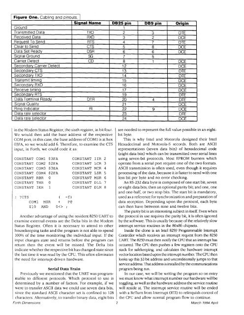
Figure One. Cabling and pinouts. 1<br />
Signal Name<br />
Ground<br />
Transmitted Data<br />
TXD<br />
Received Data<br />
RXD<br />
Request To Send<br />
RTS<br />
Clear to Send<br />
CTS<br />
Data Set Ready<br />
DSR<br />
Siqnal Ground<br />
SG<br />
Carrier Detect<br />
CD<br />
Secondary Carrier Detect<br />
Secondary CTS<br />
Secondary TXD<br />
Transmit timing<br />
Secondary RXD<br />
Receive timing<br />
Secondary RTS<br />
Data Terminal Ready<br />
DTR<br />
Siqnal Quality<br />
Rinq Indicator<br />
RI<br />
Data rate selector<br />
Data rate selector<br />
in the Modem Status Register, the sixth register, in bit four.<br />
We would then add the base address of the respective<br />
COM port; in this case, the base address of COMI is at hex<br />
03FA, so we would add 6. Therefore, to examine the CTS<br />
input, in <strong>Forth</strong>, we could code it as:<br />
CONSTANT COMl $3FA CONSTANT IIR 2<br />
CONSTANT COM2 $2FA CONSTANT LCR 3<br />
CONSTANT COM3 $3EA CONSTANT MCR 4<br />
CONSTANT COM4 $2FA CONSTANT LSR 5<br />
CONSTANT RBR 0 CONSTANT MSR 6<br />
CONSTANT THR 0 CONSTANT DLL 7<br />
CONSTANT IER 1 CONSTANT DLM 8<br />
: ?CTS ( -f)<br />
CoMl MSR + P@<br />
$10 AND O ;<br />
Another advantage of using the resident 8250 UART to<br />
examine external events are the Delta bits in the Modem<br />
Status Register. Often it is necessary to attend to other<br />
housekeeping tasks and the program is not able to spend<br />
100% of the time monitoring the individual input. If the<br />
input changes state and returns before the program can<br />
return then the event will be missed. The Delta bits<br />
indicate whether the respective bit has changed state since<br />
the last time it was read by the CPU. This often eliminates<br />
the need for interrupt-driven hardware.<br />
Serial Data Train<br />
Previously we mentioned that the UART was program-<br />
mable to different protocols. Which protocol to use is<br />
determined by a number of factors. For example, if we<br />
were to transfer ASCII data we could use seven data bits,<br />
since the standard ASCII character set is confined to 128<br />
characters. Alternatively, to transfer binary data, eight bits<br />
<strong>Forth</strong> Dimensions<br />
DB25 pin<br />
1<br />
2<br />
3<br />
4<br />
5<br />
6<br />
7<br />
8<br />
12<br />
13<br />
14<br />
15<br />
16<br />
17<br />
19<br />
20<br />
2 1<br />
22<br />
23<br />
24<br />
DB9 pin<br />
3<br />
2<br />
7<br />
8<br />
6<br />
5<br />
1<br />
4<br />
9<br />
Origin<br />
DTE<br />
DCE<br />
DTE<br />
DCE<br />
DCE<br />
DCE<br />
DCE<br />
DTE<br />
DTE<br />
DCE<br />
DCE<br />
DCE<br />
DTE<br />
DTE<br />
DCE<br />
DCE<br />
DTE<br />
DCE<br />
are needed to represent the full value possible in an eightbit<br />
byte.<br />
This is why Intel and Motorola designed their Intel<br />
Hexadecimal and Motorola-S records. Both are ASCII<br />
representations (seven data bits) of hexadecimal code<br />
(eight data bits) which can be transmitted over serial lines<br />
using seven-bit protocols. Most EPROM burners which<br />
operate from a serial port require one of the two formats.<br />
ASCII transmission is often used, even though it requires<br />
processing of the data, because it is faster to send with one<br />
less bit per byte and no error checking.<br />
An RS-232 data byte is composed of one start bit; seven<br />
or eight data bits; then an optional parity bit; and one, one<br />
and one-half, or two stop bits. The start bit is mandatory,<br />
used as a reference for synchronization and preparation of<br />
data reception. Depending upon the protocol, each byte<br />
can then have between nine and twelve bits.<br />
The parity bit is an interesting subject in itself. Even when<br />
the protocol in use requires the parity bit, it is often ignored<br />
by the software. This is usually because of the relatively slow<br />
interrupt service routines in the 80x86 chipsets.<br />
Inside the clone is an Intel 8259 Programmable Interrupt<br />
Controller which receives an interrupt request from the 8250<br />
UART. The 8259 must then notify the CPU that an interrupt has<br />
occurred. The CPU then pushes a few registers onto the CPU<br />
stack for safekeeping, and calculates the hardware interrupt<br />
vectorlocation basedupon the intermpt number. TheCPU then<br />
looks up t h 32-bit address and unconditionally jumps to that<br />
service address. That address is installed by the communications<br />
program being run.<br />
In our case, we will be writing the program so on entry<br />
we must know what interrupt number our hardware will be<br />
toggling, as well as the hardware address the service routine<br />
will reside at. The interrupt service routine will be ended<br />
with a ReTurn from Interrupt (RTI) to relinquish control of<br />
the CPU and allow normal program flow to continue.<br />
7 March 7 994 April