Chapter 11 Advanced Surface Modeling - Goodheart-Willcox
Chapter 11 Advanced Surface Modeling - Goodheart-Willcox
Chapter 11 Advanced Surface Modeling - Goodheart-Willcox

Create successful ePaper yourself
Turn your PDF publications into a flip-book with our unique Google optimized e-Paper software.
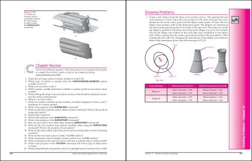
Figure <strong>11</strong>-28.<br />
A—These six<br />
surfaces form a<br />
watertight volume.<br />
B—The solid is<br />
sculpted using<br />
the SURFSCULPT<br />
command.<br />
<strong>Chapter</strong> Review<br />
Answer the following questions. Write your answers on a separate sheet of paper<br />
or complete the electronic chapter review on the companion website.<br />
www.g-wlearning.com/CAD<br />
1. Name the two basic types of surface models in AutoCAD.<br />
2. Which type of surface is created when the SURFACEMODELINGMODE system<br />
variable is set to 0?<br />
3. What is an associative surface?<br />
4. Which system variable determines whether a surface model is associative when<br />
created?<br />
5. When editing the shape of an associative surface, what should be selected to maintain<br />
the surface associativity?<br />
6. What is a network surface?<br />
7. What two system variables set the number of isolines displayed in the U and V<br />
directions of a surface model?<br />
8. What is the purpose of the SURFBLEND command?<br />
9. What are the three options used to define surface continuity? What is the result of<br />
using each option?<br />
10. Define bulge magnitude.<br />
<strong>11</strong>. What is the purpose of the SURFPATCH command?<br />
12. What is the purpose of the SURFOFFSET command?<br />
13. How do you create a new solid when using the SURFOFFSET command?<br />
14. What are the two creation type options available when using the SURFEXTEND<br />
command? What is the purpose of each option?<br />
15. What are the three object types that can be used as cutting objects when trimming<br />
a surface?<br />
16. What are the two basic ways to create a NURBS surface?<br />
17. What command is used to display control vertices on a NURBS surface?<br />
18. What command can be used to convert a 2D line or polyline into a surface model?<br />
19. What is the purpose of the THICKEN command and which type of object does<br />
it create?<br />
20. What is the preferred command to convert a watertight series of surfaces into a solid?<br />
300 AutoCAD and Its Applications—<strong>Advanced</strong><br />
A<br />
B<br />
Drawing Problems<br />
1. Create a loft surface from the three cross sections shown. The spacing between<br />
cross sections is 5 units. The circle cross section is a ∅6 circle. Use your own coordinates<br />
for the circle center point and the ellipse center points. To draw the two<br />
ellipse cross sections, refer to the dimensions given. The ellipses are centered on<br />
the same center point along the Z axis (refer to the top view). The major axis of the<br />
top ellipse is parallel to the minor axis of the lower ellipse. Use your own orientation<br />
for the ellipse axes relative to the circle (the exact orientation is not important).<br />
When creating the loft, create a procedural surface with associativity. After<br />
creating the loft, edit it by changing the dimensions of the ellipse cross sections.<br />
Refer to the dimensions given. Save the drawing as P<strong>11</strong>_01.<br />
Ellipse B<br />
Top View<br />
Cross Section Dimensions (Loft A) Edited Dimensions (Loft B)<br />
Ellipse A<br />
Ellipse B<br />
Circle<br />
Ellipse A<br />
Major diameter = 3.80<br />
Minor diameter = 2.70<br />
Major diameter = 2.70<br />
Minor diameter = 2.30<br />
Ellipse B<br />
Ellipse A<br />
Major diameter = 3.00<br />
Minor diameter = 2.00<br />
Major diameter = 6.00<br />
Minor diameter = 4.00<br />
<strong>Chapter</strong> <strong>11</strong> <strong>Advanced</strong> <strong>Surface</strong> <strong>Modeling</strong> 301<br />
Circle<br />
Loft A Loft B<br />
Drawing Problems - <strong>Chapter</strong> <strong>11</strong>