Eaton Ellipse Max Product Manual - Fusion Power System
Eaton Ellipse Max Product Manual - Fusion Power System
Eaton Ellipse Max Product Manual - Fusion Power System

You also want an ePaper? Increase the reach of your titles
YUMPU automatically turns print PDFs into web optimized ePapers that Google loves.
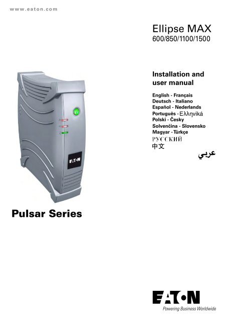
www.eaton.com<br />
Pulsar Series<br />
<strong>Ellipse</strong> MAX<br />
600/850/1100/1500<br />
Installation and<br />
user manual<br />
English - Français<br />
Deutsch - Italiano<br />
Español - Nederlands<br />
Português -<br />
Polski - Česky<br />
Solvenčina - Slovensko<br />
Magyar - Türkçe
Packaging<br />
MAX<br />
MAX<br />
2<br />
<strong>Ellipse</strong> MAX<br />
1<br />
<strong>Ellipse</strong> MAX<br />
<strong>Ellipse</strong> MAX<br />
MAX<br />
MAX<br />
2 MAU-00033 AE<br />
3<br />
<strong>Product</strong> should put on right direction as show above<br />
MAX<br />
MAX<br />
MAX<br />
MAX<br />
MAX<br />
4<br />
5<br />
MAX<br />
MAX<br />
MAX
Quick start<br />
A A<br />
FR / DIN IEC / UNIVERSAL<br />
B<br />
C<br />
D<br />
<strong>Ellipse</strong> <strong>Max</strong> 600 B<br />
<strong>Ellipse</strong> <strong>Max</strong> 850/1100 /<br />
1500 USBS<br />
<strong>Ellipse</strong> <strong>Max</strong> 600 USBS<br />
MAU-00033 AE<br />
3<br />
6<br />
C<br />
D<br />
3<br />
6<br />
3
Quick start<br />
E<br />
G<br />
<br />
<br />
<strong>Product</strong> representations not legally binding.<br />
<br />
4 MAU-00033 AE<br />
F<br />
<strong>Ellipse</strong> MAX 600 / 850 / 1100 / 1500 USBS<br />
Battery change<br />
The battery elements must be replaced exclusively by qualified personnel (risk of electrocution)<br />
Les éléments batterie ne peuvent être remplacés que par du personnel qualifié (risque d’électrocution)<br />
<strong>Ellipse</strong> <strong>Max</strong> 600 <strong>Ellipse</strong> <strong>Max</strong> 850/1100 / 1500<br />
b<br />
c<br />
OFF<br />
a<br />
◗ Warning: take care not to inverse<br />
the polarity + (red) and - (black)<br />
when connecting the batteries as<br />
this will destroy the device.<br />
f<br />
e<br />
d<br />
c<br />
b<br />
OFF<br />
◗ Attention : lors du raccordement<br />
des batteries, une inversion des<br />
polarités + (rouge) et - (noir)<br />
provoque la destruction de<br />
l'appareil.<br />
f<br />
7<br />
e<br />
d<br />
a
Technical characteristics<br />
<strong>Ellipse</strong> MAX:<br />
◗ Nominal input voltage<br />
◗ Input frequency<br />
◗ Voltage/frequency of battery backup<br />
outlets 9 in battery mode<br />
◗ Total output current for all outlets<br />
◗ Output current of battery backup outlets 9<br />
◗ Leakage current<br />
◗ Input protection<br />
◗ Transfer time<br />
◗ Telephone surge protection<br />
◗ Sealed lead-acid battery<br />
◗ Automatic battery test<br />
◗ Average battery life<br />
◗ Operating temperature<br />
◗ Storage temperature<br />
◗ Operating relative humidity<br />
◗ Operating elevation<br />
◗ Safety standards<br />
◗ Electromagnetic compatibility standards<br />
◗ Warranty<br />
◗ Dimensions (mm)<br />
◗ Weigth (Kg)<br />
Performances tested according to IEC 61643-1 (class 3) standard for 8/20 µs surge wave<br />
MAU-00033 AE<br />
600<br />
◗ UPS power 600 VA /<br />
360W<br />
AC input source protection, <strong>Ellipse</strong>:<br />
◗ Uoc (common mode / differential mode)<br />
◗ Up (common mode / differential mode)<br />
◗ In<br />
◗ Imax<br />
165V - 285V, adjustable to 150V - 285 or 175V - 285V<br />
50/60 Hz (46 - 70 Hz working range)<br />
230 V ± 7% (50/60 Hz ± 1 Hz) with pseudosinusoidal wave<br />
2.6 A max<br />
12 V, 7 Ah<br />
3.7 A max 4.8 A max 6.5 A max<br />
0.17 mA<br />
10 A resettable circuit breaker<br />
10 ms typical<br />
Tel, ISDN, ADSL, Ethernet<br />
Once a week<br />
4 years typical, depending on number of discharge cycles and<br />
temperature<br />
310x 82x 301<br />
850<br />
850VA /<br />
550 W<br />
2x12V, 7Ah<br />
0 to 35°C<br />
-25°C to +55°C<br />
0 to 85%<br />
0 to 3000 m<br />
IEC 62040-1-1, CE certified<br />
2.5 kA<br />
8 kA<br />
1100<br />
10 A max<br />
1100 VA /<br />
660 W<br />
IEC/EN 62040-2<br />
2 years<br />
310x82x410<br />
1500<br />
600 850<br />
1100 1500<br />
6kV/2kV<br />
1.5kV/1.5kV<br />
2x12V, 7Ah<br />
1500 VA /<br />
900 W<br />
2x12V, 9Ah<br />
6 10 10.2<br />
6kV/2kV<br />
1.5kV/1.3kV<br />
5
ENGLISh<br />
Operating conditions<br />
◗ This product is an Uninterruptible<br />
<strong>Power</strong> Supply (UPS) for computers<br />
and their peripherals, television<br />
sets, stereo systems and video<br />
recorders... It must not be used to<br />
supply other electrical equipment<br />
(lighting, heating, household<br />
appliances, etc.).<br />
◗ UPS can be installed in horizontal,<br />
vertical position, or placed in Rack<br />
2U (optional kit).<br />
UPS connections<br />
◗ Connect the UPS 1 to the<br />
AC-power system via a wall outlet<br />
with an earth connector, using the<br />
supplied cord 2 for a UPS with<br />
FR/DIN sockets or with the supply<br />
cord of your computer for a UPS<br />
with IEC/UNIVERSAL sockets (see<br />
figure A).<br />
◗ Plug critical equipment<br />
(computer, monitor, modem, etc.)<br />
into the outlets 9 providing<br />
battery backup power and surge<br />
protection (see figure B), taking<br />
care not to exceed the rated current<br />
indicated in amperes.<br />
◗ Other devices (printer, scanner,<br />
fax, etc.) can be connect to the<br />
filtered outlets 8 that provide<br />
surge protection (see figure B). The<br />
filtered outlets are not backed up<br />
by battery power in the event of a<br />
power outage.<br />
◗ Optional Internet modem /<br />
Network connection:<br />
A modem or Ethernet data line<br />
can be protected against surges by<br />
connecting it via the UPS. Connect<br />
the existing device cable between<br />
the wall outlet and the UPS, and<br />
use a similar cable between the<br />
UPS and the device, as indicated in<br />
figure C (cable 3 not supplied).<br />
◗ Optional COM connection:<br />
The UPS devices with<br />
communication (COM) sockets<br />
can be connected to the computer<br />
using the special USB or serial<br />
cable 6 supplied.<br />
The software available on the<br />
CD-ROM 7 (or downloadable<br />
from the eaton.com site) can be<br />
configured to monitor the UPS<br />
and the supply of power to the<br />
computer (see figures D and F).<br />
◗ Follow the indicated procedure.<br />
◗ At the same time, register for the<br />
warranty on the www.eaton.com<br />
site (see figure G).<br />
Operation<br />
8 : Filtered outlets.<br />
9 : Battery backup outlets.<br />
10 : LED ON indicate that surge<br />
protection is active on all<br />
outlets.<br />
11 : LED ON indicate a UPS fault.<br />
12 : LED ON indicate an overload<br />
on the battery backup outlets.<br />
13 : ON/OFF button for the battery<br />
backup outlets.<br />
14 : Protection circuit breaker.<br />
<strong>Ellipse</strong> MAX 600<br />
<strong>Ellipse</strong> MAX 850/1100 /1500<br />
◗ Battery charge: The UPS charges<br />
the battery as soon as it is<br />
connected to the AC outlet, whether<br />
button 13 is pressed or not. When<br />
used for the first time, the battery<br />
will only provide its maximum<br />
autonomy after it has been charged<br />
for 8 hours. It is recommended that<br />
the UPS be permanently connected<br />
to the AC power supply to ensure<br />
the best possible autonomy.<br />
◗ Switching-on the UPS: press<br />
button 13 for about 1 second.<br />
◗ Filtered outlets 8 without<br />
battery backup: Equipment<br />
connected to these outlets is<br />
supplied as soon as the AC cord 2<br />
is plugged in. They are not affected<br />
by button 13 .<br />
◗ Battery backup outlets 9 :<br />
Equipment connected to these<br />
outlets is supplied as soon as<br />
button 13 turns green (see figure<br />
E). These outlets can be turned on<br />
even if the UPS is not connected to<br />
AC power (button 13 flashes).<br />
◗ AC-power disturbance: If AC<br />
power is disturbed or fails, the UPS<br />
continues to operate on battery<br />
power. Button 13 flashes green.<br />
In normal mode, the audio alarm<br />
beeps every ten seconds, then<br />
every three seconds when the end<br />
of battery backup time is near. In<br />
silent mode (see the section on<br />
settings), the audio alarm simply<br />
beeps once when the UPS transfers<br />
to battery power.<br />
◗ If the power outage lasts longer<br />
than the battery backup time, the<br />
UPS shuts down and automatically<br />
restarts when power is restored.<br />
Following a complete discharge, a<br />
few hours are required to recharge<br />
the battery back to full backup time.<br />
◗ To save battery power, it is<br />
possible to press button 13 to cut<br />
the supply of power to the devices<br />
connected to the battery backup<br />
outlets.<br />
◗ Lightning protection: All outlets,<br />
whether backed up or simply<br />
filtered, include surge protection,<br />
whatever the position of button<br />
13 .<br />
◗ Shutdown of the battery backup<br />
outlets 9 : Press button 13 for<br />
more than two seconds.<br />
Battery disposal and safety<br />
◗ Caution. Battery service life is<br />
reduced by 50% for every ten<br />
degrees above 25°C.<br />
◗ The battery elements must be<br />
replaced exclusively by qualified<br />
personnel (risk of electrocution),<br />
with new elements approved by<br />
EATON to ensure correct operation<br />
of the UPS.<br />
◗ The battery must be disposed<br />
of in accordance with applicable<br />
regulations. To remove the<br />
battery elements, shut down the<br />
UPS (button 13 OFF), remove<br />
the power cord and proceed<br />
as indicated in page 4 "Battery<br />
change".<br />
◗ Warning: take care not to inverse<br />
the polarity + (red) and - (black)<br />
when connecting the batteries as<br />
this will destroy the device.<br />
6 MAU-00033 AE<br />
9<br />
8<br />
14<br />
13<br />
12<br />
11<br />
10<br />
8<br />
9<br />
14
Troubleshooting (For further information, visit the eaton.com site or contact after-sales support.)<br />
1<br />
2<br />
3<br />
4<br />
5<br />
6<br />
7<br />
8<br />
9<br />
10<br />
◗ The battery backup outlets 9<br />
are not supplied with power.<br />
◗ The connected devices are not<br />
supplied when AC power fails.<br />
◗ AC power is available, but the<br />
UPS operates on battery power.<br />
◗ The filtered outlets 8 are not<br />
supplied.<br />
◗ Green button 13 flashes<br />
frequently and audio alarm<br />
beeps.<br />
◗ Red LED 12 is on and the<br />
audio alarm beeps every 30<br />
seconds.<br />
◗ Red LED 11 is on and the<br />
audio alarm beeps every 30<br />
seconds.<br />
◗ Green LED 10 is off and the<br />
filtered outlets 8 are supplied.<br />
◗ The telephone line is disturbed<br />
or modem access is not<br />
possible.<br />
◗ Red LED 11 flashes.<br />
MAU-00033 AE<br />
Problem Diagnostic Solution<br />
Advanced customizing of your UPS:<br />
Sensitivity to variations of the AC power supply<br />
◗ Only to be used if frequent switching to the UPS<br />
battery due to large variations in the AC supply<br />
voltage.<br />
◗ Accessing the programming mode: with the device<br />
switched off, press button 13 for 6 s and release it<br />
once LEDs 11 12 13 have come on.<br />
◗ Display of the 3 possible voltage ranges according to<br />
the status of LEDs 11 and 12 :<br />
Normal mode<br />
(factory<br />
configuration):<br />
AC supply<br />
between 165V<br />
and 285V<br />
12<br />
11<br />
13<br />
Extended<br />
mode:<br />
AC supply<br />
between 150V<br />
and 285V<br />
12<br />
11<br />
13<br />
◗ Button 13 is not lighted on.<br />
◗ The devices are not connected to<br />
the battery backup outlets 9 .<br />
◗ Circuit breaker 14 , located under<br />
the UPS, has been tripped by an<br />
overload on the UPS output.<br />
◗ The wall outlet is not supplied.<br />
◗ Circuit breaker 14 , located under<br />
the UPS, has been tripped by an<br />
overload on the UPS output.<br />
◗ The UPS frequently operates on<br />
battery power because the AC<br />
power source is of poor quality.<br />
◗ The UPS battery backup outlets 9<br />
are overloaded.<br />
◗ A fault has occurred on the UPS.<br />
The battery backup outlets 9 are<br />
no longer supplied.<br />
◗ Surge protection is no longer<br />
provided.<br />
◗ Surge protection on the telephone<br />
line is no longer provided.<br />
◗ The battery has reached the end<br />
of its service life.<br />
Sensitive mode:<br />
AC supply<br />
between 175V<br />
and 285V<br />
Change from one mode to another by<br />
successively pressing button 13 .<br />
◗ Memorizing the mode: 10 s after the last press of the<br />
button.<br />
Audio alarm<br />
◗ Press button 13 and check that it<br />
turns green.<br />
◗ Connect the devices to the battery<br />
backup outlets 9 .<br />
◗ Disconnect excess equipment<br />
and reset the circuit breaker 14 by<br />
pressing the corresponding button.<br />
◗ Supply power to the wall outlet.<br />
◗ Disconnect excess equipment<br />
and reset the circuit breaker 14 by<br />
pressing the corresponding button.<br />
◗ Have the electrical installation<br />
checked by a professional or use<br />
another wall outlet.<br />
◗ Disconnect excess equipment<br />
connected to the battery backup<br />
outlets 9 .<br />
◗ Call after-sales support.<br />
◗ Call after-sales support.<br />
◗ Disconnect the telephone line from<br />
the wall outlet.<br />
◗ Call after-sales support.<br />
◗ Have the battery replaced.<br />
◗ Possibility of deactivating the audio alarm when the<br />
UPS is operating on the battery.<br />
◗ Accessing the programming mode: with the device<br />
switched off, press button 13 for 11 s and release it<br />
once the audio alarm sounds.<br />
◗ Display of the 2 possible audio alarm modes:<br />
Normal mode (factory<br />
configuration):<br />
the UPS emits a beep<br />
every 10 s when operating<br />
on its battery.<br />
12 Normal mode<br />
11<br />
activated:<br />
programming<br />
13<br />
by continuous<br />
beep.<br />
Silent mode:<br />
the UPS emits a single<br />
beep when switching to<br />
battery operation and<br />
then remains silent.<br />
Silent mode<br />
activated:<br />
programming<br />
by a beep every<br />
second.<br />
Change from one mode to another by<br />
successively pressing button 13 .<br />
◗ Memorizing the mode: 5 s after the last press of the<br />
button.<br />
ENGLISh<br />
7