Service Manual - EVK802P7
Service Manual - EVK802P7
Service Manual - EVK802P7

You also want an ePaper? Increase the reach of your titles
YUMPU automatically turns print PDFs into web optimized ePapers that Google loves.
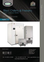
FX<br />
BLAST CHILLER<br />
ISO 14001 ISO 9001
Contents<br />
Environmental Management Policy 1<br />
Disposal Requirements 1<br />
Cabinet description 2<br />
Controller Description<br />
Controller Operation 2 to 3<br />
Alarms & Warnings 4<br />
Parameter Setting and Adjustment 4 to 6<br />
Technical Specification 6<br />
Spare Parts List 7<br />
Wiring Diagrams 8 to 15<br />
Environmental Management Policy for <strong>Service</strong> <strong>Manual</strong>s and Duets.<br />
Product Support and Installation Contractors<br />
Foster Refrigerator recognises that its activities, products and services can have an adverse impact upon the<br />
environment.<br />
The organisation is committed to implementing systems and controls to manage, reduce and eliminate its adverse<br />
environmental impacts wherever possible, and has formulated an Environmental Policy outlining our core aims. A copy<br />
of the Environmental Policy is available to all contractors and suppliers upon request.<br />
The organisation is committed to working with suppliers and contractors where their activities have the potential to<br />
impact upon the environment. To achieve the aims stated in the Environmental Policy we require that all suppliers and<br />
contractors operate in compliance with the law and are committed to best practice in environmental management.<br />
Product Support and Installation contractors are required to:<br />
1. Ensure that wherever possible waste is removed from the client’s site, where arrangements are in place all waste<br />
should be returned to Foster Refrigerator’s premises. In certain circumstances waste may be disposed of on the<br />
clients site; if permission is given, if the client has arrangements in place for the type of waste.<br />
2. If arranging for the disposal of your waste, handle, store and dispose of it in such a way as to prevent its escape<br />
into the environment, harm to human health, and to ensure the compliance with the environmental law. Guidance<br />
is available from the Environment Agency on how to comply with the waste management ‘duty of care’.<br />
3. The following waste must be stored of separately from other wastes, as they are hazardous to the environment:<br />
refrigerants, polyurethane foam, oils.<br />
4. When arranging for disposal of waste, ensure a waste transfer note or consignment note is completed as<br />
appropriate. Ensure that all waste is correctly described on the waste note and include the appropriate six-digit<br />
code from the European Waste Catalogue. Your waste contractor or Foster can provide further information if<br />
necessary.<br />
5. Ensure that all waste is removed by a registered waste carrier, a carrier in possession of a waste management<br />
licence, or a carrier holding an appropriate exemption. Ensure the person receiving the waste at its ultimate<br />
destination is in receipt of a waste management licence or valid exemption.<br />
6. Handle and store refrigerants in such a way as to prevent their emission to atmosphere, and ensure they are<br />
disposed of safely and in accordance with environmental law.<br />
7. Make arrangements to ensure all staff who handle refrigerants do so at a level of competence consistent with the<br />
City Guilds 2078 Handling Refrigerants qualification or equivalent qualification.<br />
8. Ensure all liquid substances are securely stored to prevent leaks and spill, and are not disposed of to storm<br />
drains, foul drain, surface water to soil.<br />
DISPOSAL REQUIREMENTS<br />
If not disposed of properly all refrigerators have components that can be harmful to the environment. All old<br />
refrigerators must be disposed of by appropriately registered and licensed waste contractors, and in accordance with<br />
national laws and regulations.<br />
1
Cabinet Description<br />
Controls located in the unit cover.<br />
All of the cabinet range incorporates bottom mounted refrigeration systems with the evaporator located on the back<br />
wall.<br />
The refrigerant used is R404a.<br />
Door operated fan switches stop the fans when the door is opened.<br />
FXBC10, FXBC 20, FXBC30 all 230/1/50Hz 13amp<br />
FXBC40 230/1/50Hz 16amp.<br />
The internal base is flat with drain connection in the centre to an external drain via a flexible hose. (Vaporisation tray<br />
with electric heater available as an option)<br />
FXBC 10: Blast Chiller, 10kg capacity with three GN1/1 shelves.<br />
FXBC 20: Blast Chiller, 20kg capacity with five GN1/1 shelves.<br />
FXBC 30: Blast Chiller, 30kg capacity with eight GN1/1 shelves.<br />
FXBC 40: Blast Chiller, 40kg capacity with twelve GN1/1 shelves.<br />
Controller Description<br />
The controller is mains voltage 230-50/60-1<br />
Timed Chilling LED<br />
Set-Temperature Chilling LED<br />
Storage LED<br />
Alarm LED<br />
00 - 555941<br />
The device has the following operational states:<br />
• ‘ON’ the controller is switched on and an operating cycle is running.<br />
• ‘stand-by’ the controller is switched on but no operating cycle is running.<br />
• ‘off’ the controller is switched off<br />
Degree Celsius LED<br />
If there is a power failure during a timed blast chilling operation, when the power is restored, chilling will continue from<br />
the point at which the interruption occurred.<br />
If there is a power failure during a set temperature blast chilling operation, when power is restored, chilling will start<br />
from the beginning.<br />
If there is a power failure during the storage operation, when power is restored the storage operation will be continue.<br />
2
Controller operation<br />
Prior to starting a chill operation ensure the controller is in the ‘stand-by’ mode.<br />
Timed chill operation<br />
To place the controller in ‘stand–by’ press for 2 seconds, whilst in stand-by the cabinet internal air<br />
temperature will be displayed intermittently.<br />
Press ‘PoS’ will be displayed and the Timed Chilling LED will be flashing.<br />
Press to display the chilling time, set to 90 minutes as standard, if no change to the time is required press<br />
to start the programme.<br />
If changes to the chill time are required press ‘PoS’ will be displayed and the Timed Chilling LED<br />
will be flashing, press to display the chilling time followed by to decrease the time or to<br />
increase.<br />
During chilling the display will show the time remaining with the Timed Chilling LED on.<br />
Once the chilling time is completed the controller switches to the storage mode with the display showing ‘End’ press<br />
any button to mute the alarm, press to cancel the message.<br />
Whilst the cabinet is in the storage mode the internal cabinet temperature will be displayed and the Timed Chilling LED<br />
and Storage LED will be illuminated.<br />
To stop the programme press for 2 seconds<br />
NOTE:<br />
If changes are made to the time settings on completion of the programme the time will revert back to the default setting<br />
of 90 minutes.<br />
Temperature chill operation<br />
Place the controller in ‘stand–by’ pressing for 2 seconds.<br />
Ensure that the food probe is inserted into the product prior to commencing the temperature chill programme.<br />
Press ‘PoS’ will be displayed and the Timed Chilling LED may be flashing, if it is Press<br />
again to display Set-Temperature Chilling LED flashing.<br />
Press the display will show the product end temperature, +3ºC as standard, if no change to the temperature<br />
is required press to start the programme.<br />
If changes to the chill termination temperature are required press ‘PoS’ will be displayed and the Set-<br />
Temperature Chilling LED will be flashing, press to display the chilling temperature followed by<br />
to decrease the temperature or to increase.<br />
Once the product temperature has been achieved the controller switches to storage mode with the display showing<br />
‘End’ press any button to mute the alarm, press to cancel the message.<br />
Whilst the cabinet is in the storage mode the internal cabinet temperature will be displayed and the Set-<br />
Temperature Chilling LED and Storage LED will be illuminated.<br />
To stop the programme press for 2 seconds<br />
NOTE:<br />
If changes are made to the temperature settings on completion of the programme the temperature will revert back to<br />
the default setting of +3ºC.<br />
3
Defrost<br />
Defrost will be initiated automatically in the hold mode at pre-set intervals.<br />
To initiate a manual defrost during the hold mode press for 5 seconds, defrost will start with<br />
being displayed.<br />
Alarm and Warnings<br />
d Defrost in operation<br />
AL Low Temperature Alarm<br />
AH High Temperature Alarm<br />
PR1 Air Probe fault<br />
PR2 Food Probe Fault<br />
Parameter Setting and Adjustment<br />
Setting the configuration parameters<br />
The parameters are arranged on two levels<br />
Access to the First Level<br />
To access the parameters the controller must be in the stand-by mode.<br />
To place the controller in ‘stand–by’ press for 2 seconds, whilst in stand-by the cabinet internal air<br />
temperature will be displayed intermittently.<br />
Press and for 4 seconds the display will show ‘PA’.<br />
Press ‘r0’ will be displayed.<br />
Press to display the value followed by to decrease the value or to increase the value.<br />
Press to return to the followed by to move to the next parameter.<br />
On completion of the changes press plus to exit or wait 60 seconds<br />
First Level Configuration Parameters<br />
Mnem. Definition Min. Max Default Dim. FXBC<br />
r0 Parameter r7, r8, r9 and Ra hysteresis 0.1 15.0 2.0 °K 2.0<br />
r1 Timed positive blast chilling duration 1 600 90 min. 90<br />
r2 Timed negative blast chilling duration 1 600 240 min. 240<br />
r3 Positive blast chill end point temperature (food probe) -99.0 99.0 3.0 °C 3.0<br />
r4 Negative blast chill end point temperature (food probe) -99.0 99.0 -18.0 °C -18.0<br />
r5 Set temperature positive blast chilling duration 1 600 90 min. 90<br />
r6 Set temperature negative blast chilling duration 1 600 240 min. 240<br />
r7 Positive blast chilling setpoint (air temp.) -99.0 99.0 0.0 °C 0.0<br />
r8 Negative blast chilling setpoint (air temp.) -99.0 99.0 -40.0 °C -25.0<br />
r9 Post positive blast chilling storage setpoint -99.0 99.0 2.0 °C 2.0<br />
rA Post negative blast chilling storage setpoint -99.0 99.0 -20.0 °C -20.0<br />
4<br />
d
Access to the second level<br />
To access the parameters the controller must be in the stand-by mode.<br />
To place the controller in ‘stand–by’ press for 2 seconds, whilst in stand-by the cabinet internal air<br />
temperature will be displayed intermittently.<br />
Press and for 4 seconds the display will show ‘PA’.<br />
Press ‘0’ will be displayed, press to change the setting to ‘-19’<br />
Press ‘PA’ will be displayed.<br />
Press and for 4 seconds the display will show ‘CA1’ the first parameter in the second level.<br />
Press to display the value followed by to decrease the value or to increase the value.<br />
Press to return to the followed by to move to the next parameter.<br />
On completion of the changes press plus to exit or wait 60 seconds<br />
Second Level Configuration Parameters<br />
Mnem. Definition Min. Max Default Dim. Default<br />
CA1 Air probe offset -25 25 0 °K 0<br />
CA2 Food probe offset -25 25 0 °K 0<br />
P0 Probe type (0 = PTC, 1 = NTC) 0 1 0 flag 0<br />
P1 Decimal point active (0 = No, 1 = Yes) 0 1 1 flag 0<br />
P2 Temperature unit (0 = o C, 1 = o F) 0 1 0 flag 0<br />
P3 Food probe activation (0 = No, 1 = Yes) 0 1 1 flag 1<br />
r0 Differential of parameters r7, r8, r9 and rA 0.1 15.0 2.0 °K 2.0<br />
r1 Timed positive blast chilling duration 1 600 90 min. 90<br />
r2 Timed negative blast chilling duration 1 600 240 min. 240<br />
r3 Positive blast chill end point temperature (food probe) -99.0 99.0 3.0 °C 3.0<br />
r4 Negative blast chill end point temperature (food probe) -99.0 99.0 -18.0 °C -18.0<br />
r5 Set temperature positive blast chilling duration 1 600 90 min. 90<br />
r6 Set temperature negative blast chilling duration 1 600 240 min. 240<br />
r7 Positive blast chilling setpoint (air temp.) -99.0 99.0 0.0 °C 0.0<br />
r8 Negative blast chilling setpoint (air temp.) -99.0 99.0 -40.0 °C -25.0<br />
r9 Post positive blast chilling storage setpoint -99.0 99.0 2.0 °C 2.0<br />
rA Post negative blast chilling storage setpoint -99.0 99.0 -20.0 °C -20.0<br />
rb Negative blast chilling and storage enabling 0 (NO)<br />
1<br />
(YES)<br />
1 flag 0<br />
rc Test for food probe insertion differential (0 = no test) 0.0 99.0 5 °K 5<br />
rd Duration of probe insertion test 1 99 60 sec. 60<br />
C0 Compressor start delay 0 240 0 min. 0<br />
C1 Compressor interval between starts 0 240 5 min. 5<br />
C2 Minimum compressor shut down time 0 240 3 min. 3<br />
C3 Minimum compressor run time 0 240 0 sec. 0<br />
C4 Compressor shut down with air probe error in hold (if 'C11' = 0) 0 240 10 min. 10<br />
C5<br />
Compressor shut down with air probe error in positive chill cycle<br />
(if 'C11' = 0)<br />
0 240 10 min. 10<br />
C6<br />
Compressor shut down with air probe error in negative chill cycle<br />
(if 'C11' = 0)<br />
0 240 20 min. 20<br />
C11 Food probe operation with air probe failure 0 1 0 flag 0<br />
5
d0 Defrost interval (0 = defrost not active) 0 99 8 hrs. 8<br />
d3 Defrost duration (0 = defrost not active) 0 99 30 min. 20<br />
d7 Drip time duration 0 15 2 min. 2<br />
A1 Minimum temp alarm 0.0 99.0 10 °C 5<br />
A2<br />
Minimum temp alarm type (depends on 'r9' & 'rA' [or 'r9-A1' and<br />
'rA-A1'])<br />
6<br />
0 (NO<br />
Alarm)<br />
1 1 flag 1<br />
A4 Maximum temp alarm 0.0 99.0 10 °C 5<br />
A5<br />
Maximum temp alarm type (depends on 'r9' & 'rA' [or 'r9+A4' and<br />
'rA+A4'])<br />
0 (NO<br />
Alarm)<br />
1 1 flag 1<br />
A6 Storage temp alarm delay (from start) 0 240 15 min. 15<br />
A7 Temperature alarm delay 0 240 15 min. 15<br />
A8 Drip time end high temperature alarm delay 0 240 15 min. 15<br />
A9 Maximum high temperature alarm delay (only if i0 = 0 or 1) 0 240 15 min. 15<br />
AA Blast chill cycle completion alarm duration 0 240 5 sec. 20<br />
F0<br />
Evaporator fan operation during chilling (0 = off; 1 = on; 2 = with<br />
compressor)<br />
0 2 2 flag 1<br />
F2<br />
Evaporator fan operation during hold (0 = off; 1 = on; 2 = with<br />
compressor)<br />
0 2 1 flag 1<br />
F8 Evaporator fan start up delay following defrost 0 99 0 min. 2<br />
i0<br />
Digital input operation (0 = Output a; 1 = output b; 2 = comp.<br />
protection)<br />
0 2 1 flag 0<br />
i1 Digital input contact type (0 = NO; 1 = NC; 2 = no input) 0 2 2 flag 1<br />
i2 Digital input alarm delay (only if i0 = 0 or 1) [-1 = no alarm sound] -1 120 30 min. 30<br />
i3<br />
Digital input effect duration (only if i0 = 0 or 1) [-1 = until input<br />
disabled]<br />
-1 120 15 min. -1<br />
i7 Compressor protection deactivation delay (only if 'i0' = 2) 0 120 0 min. 0<br />
u0 Relay K2 operation (0 = defrosting; 1 = evaporator fan) 0 1 1 flag 1<br />
LA Device address 1 247 1 flag 1<br />
Lb Baud rate (0 = 2.4k; 1 = 4.8k; 2 = 9.6k; 3 = 19.2k) 0 3 2 flag 2<br />
LP Parity (0 = none; 1 = odd; 2 = even) 0 2 2 flag 2<br />
E9 Not used 0 1 1 exp. 1<br />
Technical Data<br />
FXBC10 FXBC 20 FXBC 30 FXBC 40<br />
Nominal Chilling Capacity 10Kg 20Kg 30Kg 40Kg<br />
Duty @ -15°C 826w 1182w 1909w<br />
Fans 1 1 2 2<br />
Defrost Load (amps) N/A N/A N/A N/A<br />
Evaporating Temperature -15°C -15°C -15°C -15°C<br />
Refrigerant Control TEV TEV TEV TEV<br />
Refrigerant R404a R404a R404a R404a<br />
Refrigerant Quantity 1300g 1500g 2700g 2700g<br />
Electrical Supply 230/1/50 – 13amp 230/1/50 – 13amp 230/1/50 – 13amp 230/1/50 – 16amp<br />
Power Consumption<br />
Watts 738<br />
Amps 3.44<br />
Watts 1089<br />
Amps 5.1<br />
Watts 1994<br />
Amps 9.05<br />
Power absorbed W 730 1120 1990<br />
Total Heat Rejection 1564w 2271w 3903w
Spare Parts List<br />
ITEM DESCRIPTION PART NUMBER MODEL<br />
Controller EVK802 00-555941 All Models<br />
Air Probe ECSND0112A 00-555942 All Models<br />
Food Probe ECSNDX0008 00-555943 All Models<br />
Compressor MX16TB 00-555674 FXBC10<br />
Compressor CAJ9513Z 00-554334 FXBC20<br />
Compressor MS26TB 00-555682 FXBC30<br />
Compressor MS34TB 00-555677 FXBC40<br />
Condenser Fan Motor Grid Mount 16W 15470027 FXBC10, FXBC20,<br />
Condenser Fan Motor 00-555413 FXBC30, FXBC40<br />
Condenser Coil Coil 012504 00-878508-01 FXBC10<br />
Condenser Coil Coil 012654 00-554998 FXBC20<br />
Condenser Coil Coil 013521 00-555405 FXBC30, FXBC 40<br />
Drier DML 033S 00-555388 All Models<br />
Solenoid Valve EVR6 15451215 FXBC30, FXBC 40<br />
Evaporator Coil Coil 013584 00-555412 FXBC10<br />
Evaporator Coil Coil 013524 00-555410 FXBC20<br />
Evaporator Coil Coil 013475 00-555408 FXBC30, FXBC40<br />
Evaporator Fan Motor 00-555374 FXBC10<br />
Evaporator Fan Motor 00-555375<br />
FXBC20, FXBC30,<br />
FXBC40<br />
Expansion Valve Body TES2-N 68Z3417/68 15450385 All Models<br />
Orifice 00 68-20900/68-207 15451102 FXBC10, FXBC20,<br />
Orifice 02 68-2092/68-2072 15451104 FXBC30, FXBC40<br />
Expansion Valve Solder Adaptor 15450910 All Models<br />
High Pressure Switch (28 BAR) 00-555386 All Models<br />
Low Pressure Switch (4PSI) 00-555387 FXBC30, FXBC 40<br />
Door Switch Circular (Reed Type) 00-555829 All Models<br />
Door Switch Magnet Circular 00-555828 All Models<br />
Door Gasket Magnet 597.5x385 01-232996-01 FXBC10<br />
Door Gasket Magnet 597.5x551.5 01-232909-01 FXBC20<br />
Door Gasket Magnet 597.5x1151.5 01-232852-01 FXBC30<br />
Door Gasket Magnet 597.5x1151.5 01-232852-01 FXBC40<br />
7
FXBC 10 Wiring Diagram<br />
8
FXBC 10R Wiring Diagram<br />
9
FXBC 20R Wiring Diagram<br />
10
FXBC 20R Wiring Diagram<br />
11
FXBC 30 Wiring Diagram<br />
12
FXBC 30R Wiring Diagram<br />
13
FXBC 40 Wiring Diagram<br />
14
FXBC 40R Wiring Diagram<br />
15
Foster European Operations<br />
France<br />
Foster<br />
Refrigerator France SA<br />
Tel:<br />
(33) 01 34 30 22 22. Fax: (33) 01 30 37 68 74.<br />
Email:<br />
commercial@fosterfrance.com<br />
Germany<br />
Foster<br />
Refrigerator Gmbh,<br />
Tel:<br />
(49) 7819907840. Fax (49)7819907844.<br />
Email:<br />
info@foster-gmbh.de<br />
Foster Refrigerator<br />
Oldmedow<br />
Road<br />
Kings<br />
Lynn<br />
Norfolk<br />
PE30<br />
4JU<br />
Tel:<br />
01553 691122<br />
Fax:<br />
01553 691447<br />
Website:<br />
www.fosterrefrigerator.co.uk<br />
Email: sales@foster-uk.com<br />
a Division of ‘ITW (UK) Ltd’<br />
FXBC/<br />
SM 06/07<br />
19