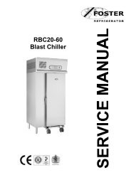
Blast Chillers & Freezers - Foster Spares & Service
Blast Chillers & Freezers - Foster Spares & Service
Blast Chillers & Freezers - Foster Spares & Service

You also want an ePaper? Increase the reach of your titles
YUMPU automatically turns print PDFs into web optimized ePapers that Google loves.
<strong>Blast</strong> <strong>Chillers</strong> & <strong>Freezers</strong><br />
Cabinet & Modular Models<br />
FC1-11 Touchpad Controller<br />
English<br />
Feb 2013 Version 1<br />
ISO 9001 ISO 14001<br />
By Appointment to<br />
Her Majesty Queen Elizabeth II<br />
Suppliers of Commercial Refrigeration<br />
<strong>Foster</strong> Refrigerator, King’s Lynn<br />
Call: +44 (0)843 216 8800 Fax: +44 (0)843 216 4700 Email: support@foster-uk.com<br />
www.fosterrefrigerator.co.uk<br />
A Division of ITW Ltd<br />
<strong>Foster</strong> Refrigerator,<br />
Oldmedow Road,<br />
King’s Lynn,<br />
Norfolk, PE30 4JU<br />
United Kingdom<br />
Original <strong>Service</strong> Manual<br />
1
GB<br />
Manual Information & Health & Safety Notes 1<br />
Environmental Management Policy 2<br />
Disposal Requirements & Electrical Safety 2<br />
Start Up & Operation 3<br />
What is <strong>Blast</strong> Chilling & Freezing? The Cycle Descriptions. 3 to 5<br />
Touchpad Display Icons 5 to 6<br />
Guide to <strong>Blast</strong> Chilling & User Adjustment Modes 6 to 7<br />
FC1-11 Parameters & Configuration of Parameters 7 to 9<br />
Default Parameters Explained 10 to 18<br />
Individual Cabinet Parameter Values 19 to 21<br />
Engineer Aids – Manual Relay & Footprint Testing 22<br />
Technical Data for <strong>Blast</strong> Chiller/Freezer Models & FC1-11 Technical Data 23 to 25<br />
Modular <strong>Blast</strong> Chiller 3 Food Insertion Probe Configuration 26<br />
Troubleshooting & Alarms 27 to 30<br />
The products and all information in this manual are subject to change without prior notice.<br />
We assume by the information given that the person(s) working on these refrigeration units are<br />
fully trained and skilled in all aspects of their workings. Also that they will use the appropriate safety<br />
equipment and take or meet precautions where required.<br />
The service manual does not cover information on every variation of this unit; neither does it cover the<br />
installation or every possible operating or maintenance instruction for the units.<br />
Make sure the power supply is turned off before making any electrical<br />
repairs.<br />
To minimise shock and fire hazards, please do not plug or unplug the unit<br />
with wet hands.<br />
During maintenance and cleaning, please unplug the unit where required.<br />
Care must be taken when handling or working on the unit as sharp edges<br />
may cause personal injury, we recommend the wearing of suitable PPE.<br />
Ensure the correct moving and lifting procedures are used when relocating a<br />
unit.<br />
Do NOT use abrasive cleaning products, only those that are recommended.<br />
Never scour any parts of the refrigerator. Scouring pads or chemicals may<br />
cause damage by scratching or dulling polished surface finishes.<br />
Failure to keep the condenser clean may cause premature failure of the<br />
motor/compressor which will NOT be covered under warranty policy.<br />
Do NOT touch the cold surfaces in the freezer compartment. Particularly<br />
when hands are damp or wet, skin may adhere to these extremely cold<br />
surfaces and cause frostbite.<br />
Please ensure the appropriate use of safety aids or Personnel Protective<br />
Equipment (PPE) are used for you own safety.<br />
1
GB<br />
Product Support and Installation Contractors.<br />
<strong>Foster</strong> Refrigerator recognises that its activities, products and services can have an adverse impact<br />
upon the environment.<br />
The organisation is committed to implementing systems and controls to manage, reduce and<br />
eliminate its adverse environmental impacts wherever possible, and has formulated an<br />
Environmental Policy outlining our core aims. A copy of the Environmental Policy is available to all<br />
contractors and suppliers upon request.<br />
The organisation is committed to working with suppliers and contractors where their activities have<br />
the potential to impact upon the environment. To achieve the aims stated in the Environmental<br />
Policy we require that all suppliers and contractors operate in compliance with the law and are<br />
committed to best practice in environmental management.<br />
Product Support and Installation contractors are required to:<br />
1. Ensure that wherever possible waste is removed from the client’s site, where arrangements are in<br />
place all waste should be returned to <strong>Foster</strong> Refrigerator’s premises. In certain circumstances waste<br />
may be disposed of on the client’s site; if permission is given, if the client has arrangements in place<br />
for the type of waste.<br />
2. If arranging for the disposal of your waste, handle, store and dispose of it in such a way as to<br />
prevent its escape into the environment, harm to human health, and to ensure the compliance with<br />
the environmental law. Guidance is available from the Environment Agency on how to comply with<br />
the waste management ‘duty of care’.<br />
3. The following waste must be stored of separately from other wastes, as they are hazardous to the<br />
environment: refrigerants, polyurethane foam, and oils.<br />
4. When arranging for disposal of waste, ensure a waste transfer note or consignment note is<br />
completed as appropriate. Ensure that all waste is correctly described on the waste note and include<br />
the appropriate six-digit code from the European Waste Catalogue. Your waste contractor or <strong>Foster</strong><br />
can provide further information if necessary.<br />
5. Ensure that all waste is removed by a registered waste carrier, a carrier in possession of a waste<br />
management licence, or a carrier holding an appropriate exemption. Ensure the person receiving the<br />
waste at its ultimate destination is in receipt of a waste management licence or valid exemption.<br />
6. Handle and store refrigerants in such a way as to prevent their emission to atmosphere, and<br />
ensure they are disposed of safely and in accordance with environmental law.<br />
7. Make arrangements to ensure all staff who handle refrigerants do so at a level of competence<br />
consistent with the City Guilds 2078 Handling Refrigerants qualification or equivalent qualification.<br />
8. Ensure all liquid substances are securely stored to prevent leaks and spill, and are not disposed of into storm<br />
drains, foul drain, or surface water to soil.<br />
If not disposed of properly all refrigerators have components that can be harmful to the<br />
environment.<br />
All old refrigerators must be disposed of by appropriately registered and licensed waste contractors, and<br />
in accordance with national laws and regulations.<br />
<strong>Foster</strong> Refrigerator recommends that the equipment is electrically connected via a Residual Current<br />
Device; such as a Residual Current Circuit Breaker (RCCB) type socket, or through a Residual Current<br />
Circuit Breaker with Overload Protection (RCBO) supplied circuit.<br />
2
GB<br />
Initial Set Up<br />
After unpacking clean and allow the cabinet to stand for 2 hours before turning on.<br />
Ensure the cabinet is situated where neither hot nor cold air sources will affect its performance. Make sure that a<br />
minimum clearance of 150mm around the cabinet is available for ventilation and effective operation. There is no<br />
minimum clearance for above the cabinets. Connect the unit to a suitable mains power outlet and turn the supply<br />
on. Please note that the BCT36 will require a 16amp supply and the BCFT36 and both 51kg models will require a 3<br />
phase supply.<br />
Do not plug or unplug the unit with wet hands.<br />
Initialisation screen<br />
Home Screen<br />
After power is applied to the unit the controller display will show the initialisation<br />
screen. This will only show for a few minutes stating both ‘Booting’ and then<br />
displaying the software version at the bottom of the screen. When the controller<br />
has completed initialisation the screen will revert to the ‘Home Screen’.<br />
This is shown after initialisation and when no programmes are running. From this<br />
page a cycle can be launched. Select the cycle type by pressing the relevant<br />
cycle button and then press ‘Start’. This page also shows the date, time and<br />
current air temperature and allows access to the ‘Settings Home Screen’ and<br />
‘Information’ function.<br />
<strong>Blast</strong> Chilling is a process that reduces the temperature of cooked food quickly and safely by halting the cooking<br />
process; locking in its colour, flavour, texture and nutritional value. The Department of Health guideline states that<br />
to safely blast chill food its temperature must be reduced from +70°C to +3°C within 90 minutes.<br />
When freezing food slowly, large ice crystals are created which can damage, dry out and break down the<br />
physical structure of the food leaving you with an unrecognisable product. The process of <strong>Blast</strong> Freezing reduces<br />
the products temperature quickly from +70°C to -18°C in no more than 240 minutes therefore meaning smaller<br />
crystals form and damage to product is less likely.<br />
Pre Chill<br />
This type of chill ensures that the cabinet’s actual interior temperature is correct prior to a chill cycle. This cycle will<br />
run until either the cycle time has lapsed or the internal air temperature has been achieved (whichever occurs first).<br />
After this the controller will ensure the unit remains’ in a ‘Hold’ mode until required to start a chill cycle. Performing<br />
this Pre Chill will also improve chilling performance.<br />
Soft Chill<br />
Normally this kind of cycle is used on delicate produce such as mousse, pastries, custards, fruits and vegetables.<br />
It’s also suitable for fine or thin products.<br />
The ‘Soft Chill’ cycle rapidly, but gently, reduces the product temperature to an even +3°C by controlling the air<br />
temperature to between +0.5°C and +3.5°C. The product should never go into a minus temperature range, if so<br />
damage will occur to the product in the form of texture, consistency, appearance or even dehydration. This cycle<br />
would ideally take no longer than 90 minutes to achieve, but this is dependent on the product type and load<br />
amount.<br />
Hard Chill<br />
This is more of a general purpose cycle. ‘Hard chill’ brings food temperature down to +3°C in no more than 90<br />
minutes (depending on the product type and load). Ideally this is used for meat pies, lasagne, pasta, soups/stews<br />
and or individually portioned meals – products containing a higher fat content.<br />
3
GB<br />
The air temperature is controlled between -20°C and +2°C in two phases. Firstly it will be reduce to -20°C<br />
for the first 80% of the cycle or until the product probe has been lowered significantly. This will extract the maximum<br />
amount of heat quickly from the product.<br />
The air temperature is then increased to +1°C for the final section of the cycle. This time reduces surface damage<br />
and will ensure quality levels.<br />
Hard Max Chill<br />
The ‘Hard Max’ cycle is used to reduce the product temperature to around +3°C. The air temperature in this<br />
incidence is maintained at -20°C for the whole cycle. After either a pre-determined time or the product temperature<br />
has been achieved the air temperature is allowed to rise into the ‘hold’ value where the temperature is maintained<br />
until the cycle is stopped.<br />
The average cycle time is 90 minutes but actual chill time is dependent on the product type or load. ‘Hard Max’ is<br />
normally used with packaged or specialist products<br />
Freeze<br />
By ‘Shock Freezing’ you change the state of the food into a frozen product and this enables a long term storage<br />
facility. To achieve this the cycle rapidly reduces the product temperature until a uniform -18°C is achieved. To<br />
enable this, the air temperature is maintained at around -35°C. This cycle normally runs for around 240 minutes;<br />
however the actual duration is dependent upon several factors:<br />
Product type<br />
Load<br />
Quantity<br />
How (if applicable) portions are organised<br />
The initial product temperature<br />
The type of storage container used<br />
Long Term Storage or Hold Mode (Conservation)<br />
When a chill cycle has completed; either by time lapsed or temperature of product, the controller will automatically<br />
enter a ‘hold’ mode. The display will show the ‘End’ screen and the EOC (End of Cycle) alarm will sound. After this<br />
there are three possible options available:<br />
> Press and hold the ‘Stop’ Button.<br />
As soon as the stop button has been pressed & held the EOC alarm will silence. While holding the button<br />
the display will show the stopping screen. If the button is not held until all three progression blocks have<br />
filled red then the ‘End’ screen will not display. If held correctly the filled blocks will disappear and the cycle<br />
will terminate, in turn displaying the ‘Home’ screen.<br />
> Press and Release the ‘Mute’ button.<br />
If you press the ‘Mute’ button the EOC alarm will silence and the display will show an active ‘Hold’ screen.<br />
This screen will have a green border and progress blocks which will fill at a rate of one per second.<br />
The display will also show the competed hold time and the total cycle time at the top centre of the<br />
screen. The controller will maintain the hold mode indefinitely; allowing defrosts (although the EOC alarm<br />
will not sound again) until the stop button is pressed and held (as described above).<br />
> Do nothing.<br />
In this case the EOC will sound for a length of time (determined by the parameter EOC Max. Time) until<br />
going automatically into a ‘Hold’ screen. This ‘Hold’ screen will be as described above but with no alarm<br />
sounding and instead of a green boarder will show in red. Again the progress blocks will fill one per second<br />
but again in red.<br />
This hold cycle will continue indefinitely; allowing defrosts, but the EOC will sound periodically as<br />
determined by the parameter ‘EOC Rpt. Int’ until the ‘Stop’ button is pressed and held (initiating the first<br />
instance described – the stopping screen).<br />
During the hold mode the cycle parameter will determine the temperature, but generally the air temperature<br />
will be held at +2°C following a chill cycle and -21°C following a freeze.<br />
4
GB<br />
Evaporator Fan Hold or Surface Protection.<br />
To rapidly remove heat from product these units achieve this with the combination of a powerful refrigeration<br />
system and evaporator fans. By moving large amounts of cool air around the product, which is actually cooler than<br />
the air temperature, causes a ‘Wind Chill Effect’.<br />
In some cases this can damage the product in the form of ‘Frost Burn’. Product can show this in the form of<br />
discolouration, dehydration and or localised freezing. To prevent this, a function called Surface Protection can be<br />
used. This function limits the evaporator fan usage during cycles and hold mode and in doing so slows the air<br />
speed at set times (as pre-determined or set by the operator within the operating parameters).<br />
There are four modes which are determined by parameter ‘Fan Hold Mode’:<br />
> ON – the evaporator fans run continuously in hold mode.<br />
> CYCLE – the evaporator fans are switched in conjunction with the condensing system.<br />
> AUTO – the evaporator fans run with the condensing system but additionally cycle in conjunction with<br />
parameters ‘Time Fan Stop’ (period the evaporator fans are stopped during the off cycle) and ‘Time Fan<br />
Run’ (period the evaporator fans run during the off cycle) in the off cycle.<br />
> OFF – Evaporator fans are stopped in hold mode, operating in chill and defrost (as required) only.<br />
This function requires no interference from the operator and will happen automatically within the required cycles.<br />
Cycle Description Time Elapsed<br />
Chill Cycle Symbol Air (T1) Temperature<br />
Cycle Progress Bar<br />
Detail Information<br />
Day & Current Time<br />
Surround Signal<br />
Stop Button Information Button<br />
(Some icons or switches are only visible during adjustment, when activated by parameters or<br />
through operation/manual selection).<br />
Buttons & Icons<br />
Home – When selected on any screen this<br />
will revert you to the home screen<br />
Settings – This will take you into the ‘Settings<br />
Menu’ where changes can be made to the<br />
language, date, time etc.<br />
Back - When pressed this will take you back<br />
to the previous screen<br />
Information – When pressed this will give a<br />
summary of what is currently happing with<br />
the unit<br />
Screen Feedback Signal<br />
When an icon or button is selected on screen a single beep will be heard to confirm the action requested.<br />
5
GB<br />
Surround Signal Colour Coding<br />
These four different screen surround signal colours represent the following:<br />
<strong>Service</strong> or Maintenance<br />
Mode. User<br />
modification in<br />
progress.<br />
Controller not<br />
operating or in<br />
Standby. User<br />
attention not required.<br />
Process or system<br />
issue. User intervention<br />
required.<br />
Chill cycle under way.<br />
User attention not<br />
required.<br />
Guide to <strong>Blast</strong> Chilling<br />
Food Type Includes<br />
<strong>Blast</strong> Chill<br />
Programme<br />
Time to<br />
Chill (Mins)<br />
Time to Shock<br />
Freeze (Mins)<br />
Meat Beef, pork, lamb, poultry & mince<br />
Fried, poached or baked –<br />
Hard 40 – 90 60 – 240<br />
Fish<br />
haddock, plaice, salmon, cod fillets<br />
etc.<br />
Soft 30 – 90 60 – 240<br />
Prepared Dishes<br />
Stews & casseroles, lasagne,<br />
risotto, shepherd’s pie etc.<br />
Hard 50 – 90 90 – 240<br />
Vegetable & Pulses<br />
Stewed or roasted veg, rice &<br />
Soft 30 – 90 60 – 240<br />
potatoes etc.<br />
Fruit Stewed & cooked fruits. Soft 60 – 90 60 – 240<br />
Bakery Cakes. Hard 30 – 90 70 – 240<br />
Delicate Bakery Pastries. Hard 60 – 90 50 – 240<br />
Desserts<br />
Fruit based desserts & egg based<br />
flans.<br />
Soft 30 – 90 70 – 240<br />
Other Desserts<br />
Sponge puddings & dense desserts<br />
such as cheesecake.<br />
Hard 30 – 90 70 – 240<br />
(Note: All times listed should be used as a guide only, and will depend on type, size & quantity).<br />
User Settings<br />
The following three screen options can all be accessed by starting from the ‘Home Screen’ then<br />
by using the ‘Settings Icon’, select the ‘Settings Home Screen’. From here you can then select<br />
the menu required:<br />
Time/Date Setting<br />
To amend the time or date, select the ‘Set Time and Date’ menu option which<br />
opens a new screen. From here, using the up and down arrows you<br />
can edit not only the time and date but also the format this shows in.<br />
Once you have finished modifying these settings press the set<br />
button to save the changes made. If this isn’t pressed or the screen<br />
is left for roughly 1 minute no changes will be saved.<br />
Languages (Only where available)<br />
Select the languages menu and then the flag of the language you require the<br />
controller to display all further text in. If you don’t set a specific language within<br />
20 seconds the controller will revert to the home screen without making any<br />
changes. By selecting a flag the language displayed will change from that point<br />
onwards.<br />
6
GB<br />
Manual Defrost<br />
Select ‘Defrost’ from the menu page. This will initiate a manual defrost and the<br />
defrost screen will show with the time counting down until the end of cycle,<br />
displayed by progression blocks. These slowly fill with colour to show<br />
the cycle progress.<br />
Other Defrost modes:<br />
A defrost doesn’t have to be activated manually, an automatic defrost function is<br />
also determined by parameter ‘Def.Start Mode’. This can be active in five mode<br />
options:<br />
> NONE – an automatic defrost is inhibited<br />
> TM HOLD – the defrost interval clock is increased only during the ‘Hold’ phase.<br />
> TM TOTAL – the defrost interval clock is increased during both ‘Chill’ and ‘Hold’ phases but only if any<br />
time spent in standby is less than or equal to parameter ‘Chill Int.’<br />
> FST HOLD – the defrost time clock is only increased in ‘Hold’ mode and when the conditions for frost<br />
accumulation exist (i.e. the coil temperature is less than 0°C).<br />
> FST TTL – the defrost time clock is only increased when in Chill and Hold, and conditions for frost<br />
accumulation exist but only if time in standby is less than or equal to ‘Chill Int.’<br />
The time in which two defrosts ( 2 automatic or 1 automatic and 1 manual) can occur is determined by ‘Def.Start'<br />
Mode’ parameter ‘Defrost Int.’ (this is shown in hours).<br />
‘Chill Int’ also indicates the minimum time period between the end and start of a time based defrosts.<br />
There are three types of defrost allowed by parameter ‘Def.Type’:<br />
> Timed Off Cycle (TIME) – using the evaporator fan(s) only for a pre-determined time period.<br />
> Electric (ELEC) – using the electric rod heaters, the defrost relay is energised for the ‘Max Def. Time’ or<br />
until ‘Def.End Temp’ is achieved; whichever occurs first.<br />
> Hot Gas (HOT GAS) – utilising ‘hot gas’ by running the compressor and energising the defrost relay<br />
together for ‘MAX Def.Time’ or until ‘Def. End Temp’ is achieved; whichever occurs first.<br />
When shown on screen you can press this button at any time you will be able to halt a cycle or function.<br />
This needs to be pressed and held until the progression blocks are filled. At this point it is safe to<br />
release the button and cancelation of any function will complete.<br />
If this is released and or pressed briefly, without allowing the blocks to fill, will result in the function or<br />
cycle to continue.<br />
<strong>Service</strong> Settings Menu<br />
Access to this menu is vital if you wish to adjust any parameter settings.<br />
From the ‘Home’ screen select the ‘Settings Icon’ to enter the ‘<strong>Service</strong> Settings’ screen.<br />
You will be prompted to enter a security code at this point. Using the up and down arrows enter 1 3 1<br />
and select the ‘Enter’ button. If entered incorrectly the page will revert to the Home Page (likewise if<br />
nothing is entered for 20 seconds). You have now unlocked the controller to amend parameters.<br />
Cycle Parameters<br />
Parameters should not be changed unless you have an understanding of their purpose and the following<br />
instructions are fully understood.<br />
This ‘<strong>Service</strong> Setting’ screen allows access to all 5 chilling cycles, control and system parameter settings as well as<br />
the relay test facility.<br />
7
GB<br />
To amend a ‘Cycle’ please do the following:<br />
> Select the cycle requiring amendment<br />
> Select the parameter you wish to change so a new mini screen pops up over the menu<br />
> Using either the number pad displayed or the scroll menu select the change you wish to make and press<br />
the green tick to confirm the change. If you wish to leave this pop up without making a change press the<br />
red cross.<br />
> When all changes have been made press the back button to revert to the ‘<strong>Service</strong> Setting’ screen.<br />
If the green tick is not pressed or the screen is left for 20 seconds then the amendment will not be saved and the<br />
display will return to the home screen.<br />
To amend ‘System’ and ‘Control’ parameters is very similar.<br />
As before instead of selecting a cycle, press ‘System’ or ‘Control’ followed by the parameter that requires<br />
amending.<br />
As shown above amend and save in the same way by confirming the change with the green tick button.<br />
To select these parameters you may be required to use a stylus or pen (with the lid fitted) to carry out the changes<br />
accurately.<br />
All parameters are shown as separate tabs/pages grouped as shown below:<br />
8
GB<br />
These updates screens are only used when firmware updates are being carried out:<br />
9
GB<br />
Section Parameter Range Description Unit Default<br />
Enabled NO or YES ‘Pre Chill’ program availability Func. YES<br />
Air Temperature -50 to 120° Air temperature set point during ‘Pre Chill’ phase. °C 5.0<br />
Chill Duration 0 to 600 mins Duration of ‘Pre Chill’ phase. Min. 15<br />
Hold Temperature -50 to 120° Air temperature set point following completion of ‘pre Chill’ phase °C 3.0<br />
Enabled NO or YES ‘Soft Chill’ program availability Func. YES<br />
Air Temperature -50 to 120° Air temperature set point during ‘Soft Chill’ phase °C 1.0<br />
Chill Duration 0 to 600 mins Duration of ‘Soft Chill’ phase Min. 90<br />
Chill Temperature -50 to 120° Temperature to be achieved by food insertion probe (T3), thus ending ‘Soft Chill’ phase. °C 4.0<br />
Hold Temperature -50 to 120° Air temperature set point following completion of ‘Soft Chill’ phase °C 3.0<br />
Enabled NO or YES ‘Hard Chill’ program availability Func. YES<br />
Air Temp Stage1. -50 to 120° Air temperature set point during ‘Hard Chill’ 1 st stage °C -15.0<br />
Air Temp Stage2. -50 to 120° Air temperature set point during ‘Hard Chill’ 2 nd stage °C 1.0<br />
Chill Duration 0 to 600 mins Duration of ‘Hard Chill’ phase Min. 90<br />
Chill Temperature -50 to 120° Temperature to be achieved by food insertion probe (T3), thus ending ‘Hard Chill’ phase °C 4.0<br />
Hold Temperature -50 to 120° Air temperature set point following completion of ‘Hard Chill’ phase °C 3.0<br />
Percentage of the ‘Hard Chill’ cycle time to elapse before the air temperature is lifted<br />
Change Time 0 to 100%<br />
from 1 st to 2 nd % 80<br />
stage (Air temp.1’ to Air Temp.2’) during timed chill.<br />
Food insertion probe (T3) temperature to be achieved before the air temperature is lifted<br />
Change Temp. -50 to 120°<br />
from 2st to 2 nd °C 15.0<br />
stage (Air Temp.1 to Air Temp.2) during temperature chill<br />
Enabled NO or YES ‘Hard Max’ program availability Func. YES<br />
Air Temperature -50 to 120° Air Temperature set point during ‘Hard Max’ phase °C -15.0<br />
Chill Duration 0 to 600 mins Duration of ‘Hard Max’ phase Min. 90<br />
Chill Temperature -50 to 120° Temperature to be achieved by food insertion probe (T3), thus ending ‘Hard Max’ phase °C 4.0<br />
Hold Temperature -50 to 120° Air Temperature set point following completion of ‘Hard Max’ phase. °C 3.0<br />
Enabled NO or YES ‘Shock Freeze’ program availability Func. NO<br />
Air Temperature -50 to 120° Air Temperature set point during ‘Shock Freeze’ phase °C -30.0<br />
Chill Duration 0 to 720 mins Duration of ‘Shock Freeze’ phase Min. 240<br />
Determines if food insertion probe (T3) is enabled during ‘Shock Freeze’ phase ( allowing<br />
Insertion Probe NO or YES<br />
Func. NO<br />
temperature based chill cycle)<br />
Temperature to be achieved by food insertion probe (T3), thus ending ‘Shock Freeze’<br />
Chill Temperature -50 to 120°<br />
°C -21.0<br />
phase (if Insertion Probe = Yes)<br />
Hold Temperature -50 to 120° Air Temperature set point following completion of ‘Shock Freeze’ phase °C -21.0<br />
Pre<br />
Chill<br />
Soft Chill<br />
Hard Chill<br />
Hard<br />
Max<br />
Freeze<br />
10
GB<br />
Section Para Range Description Dim Default<br />
Auto Prog. Time<br />
Automatically determines chill cycle type (time or temp). If after ‘Auto Prog<br />
0 to 120 min<br />
Time’, the ‘T1’ temp + ‘Auto Prog Hys’ ≥’T3’ probe temp = time based chill. If Min. 10<br />
‘T1’ temp +’Auto Prog Hys’ < ‘T3’ temp = temperature based chill cycle.<br />
Auto Prog. Hys<br />
Automatically determines chill cycle type (time or temp). If after the ‘Auto<br />
Prog Time’, the ‘T1’ temp + ‘Auto Prog Hys’ ≥’T3’ probe temp = time based<br />
‘0 to 50°<br />
°K 10<br />
chill. If ‘T1’ temp +’Auto Prog Hys’ < ‘T3’ temp = temperature based chill<br />
cycle.<br />
Chill Hysteresis ‘0 to 50° Differential value applied to temperature cycle during ‘Chill’ mode °K 3<br />
Hold Hysteresis ‘0 to 50° Differential value applied to temperature cycle during ‘ Hold’ mode °K 3<br />
Comp. Rest Time<br />
Minimum time between the compressor stopping and restarting based on ‘T1’<br />
0 to 60 min<br />
Min. 2<br />
temperature<br />
Comp. Stop Dly<br />
Compressors stop delay after door had been opened (When ‘Digital I/P 0’ =<br />
0 to 60 min<br />
Min. 1<br />
‘Door’)<br />
T1 Fail Run<br />
Upon failure of ‘T1’ probe – thermostat run time (If ‘T1 Fail Run’ = ‘0’<br />
0 to 60 min<br />
Min. 1<br />
compressor will remain be off with ‘T1’ probe fault).<br />
T1 Fail Stop<br />
Upon failure of ‘T1’ probe – thermostat stop time (If ‘T1 Fail Stop’ = ‘0’ and<br />
0 to 60 min<br />
Min. 2<br />
‘T1 Fail Run’ ≥ ‘2’ compressor will always be on with ‘T1’ probe fault).<br />
Capacity Enable Capacity Control Operation Mode:<br />
OFF Disables ‘Capacity Control’, regardless of program mode or temperature<br />
Enables ‘Capacity Control’ in both the ‘Chill’ & ‘Hold’ mode. Energises relay<br />
AUTO<br />
when ‘T1’ temperature less than or equal to cycle temperature set point +<br />
Func. OFF<br />
cycle hysteresis + Capacity Hys’<br />
‘Capacity Control’ only in ‘hold’ mode. Relay energised when ‘T1’ temperature<br />
HOLD<br />
less than or equal to cycle ‘Hold’ temperature set point + ‘Hold hysteresis’ +<br />
‘Capacity Hys’<br />
Capacity Hys ‘0 to 50° Differential Value applied to determine Capacity Control operation °K 3<br />
EOC Max Time<br />
The time that End of Cycle (EOC) alarm sounds for before automatically<br />
0 to 720 min<br />
muting when not acknowledged (If ‘EOC Max Time’ = ‘0’ the EOC alarm will Min. 2<br />
not automatically mute)<br />
EOC Rpt. Int.<br />
Time between un-acknowledged EOC alarm being automatically muted and<br />
0 to 720 min<br />
Min. 30<br />
resounding. If ‘EOC Rpt.Int’ – ‘0’ the alarm will not resound<br />
Start Mode: Defrost Mode Configuration:<br />
NONE<br />
Defrost is inhibited<br />
(NONE)<br />
TIME IN HOLD<br />
Defrost interval clock is increased only during ‘Hold’ phase.<br />
TM<br />
(TM HOLD)<br />
Func.<br />
HOLD<br />
TIME TOTAL<br />
Defrost interval clock is increased during both ‘Chill’ and ‘hold’ phase but only<br />
(TM TTL)<br />
if time in Standby ≤ ‘Chill Int’.<br />
FROST INHOLD<br />
Defrost time clock is only increased when in Hold and conditions for frost<br />
(FST HOLD)<br />
accumulation exist.<br />
11<br />
Control<br />
Defrost
GB<br />
FROST TOTAL<br />
Defrost time clock is only increased when in Chill and Hold, and conditions for<br />
(FST TTL)<br />
frost accumulation exists but only if time in Standby ≤= ‘Chill Int’.<br />
Chill Interval<br />
The minimum time period between ending one chill cycle and starting another<br />
0 to 120 min<br />
to allow time based defrost (i.e. if time in ‘Standby’ more than ‘Chill Int’ Min. 30<br />
defrost time clock resets).<br />
Defrost Interval 0 to 24 hrs. The time interval between defrosts. Hrs. 6<br />
End Temperature<br />
The temperature to be measured by evaporator (T2) probe required to<br />
0 to 120°<br />
°C 20<br />
terminate defrost.<br />
Max Duration 0 to 120 min The maximum length of time for a defrost period. Min. 30<br />
Type: Defrost Type:<br />
OFF CYCLE<br />
Defrost is performed using evaporator fans only for a pre-determined time<br />
(OFF)<br />
period.<br />
Defrost is performed using electric rod heaters – defrost relay (RL3)<br />
ELECTRIC<br />
energised for Max Def. Time’ or until ‘Def. End Temp’ is achieved (whichever Func. OFF<br />
(ELEC)<br />
occurs first).<br />
Defrost is performed using hot gas – compressor (RL1) & defrost relay (RL3)<br />
HOT GAS<br />
energised for ‘Max Def. Time’ or until ‘Def. End Temp’ is achieved *whichever<br />
(HOT GAS)<br />
occurs first).<br />
Drain Down<br />
Time period following a defrost to allow melt water to drain prior to<br />
0 to 120 min<br />
Min. 2<br />
recommencing cooling<br />
Fans In Defrost NO or YES Determines whether the evaporator fan(s) run during the defrost period. Flag YES<br />
Fan Restart Temp<br />
The temperature that the evaporator coil should reach (measured by T2)<br />
-50 to 120°<br />
°C 0<br />
before restarting the evaporator fans (RL2) – subject to ‘Max. Fan Stop’<br />
Max Stop After Def Maximum period evaporator fans are stopped following restarting condensing<br />
0 to 120 min<br />
Min. 0<br />
system after defrost<br />
Min. Fan Stop 0 to 120 sec. Minimum period evaporator fans are stopped (following door opening etc.) Sec. 0<br />
Hold Mode Evaporator Fan Operation in Hold Mode<br />
ON Evaporator fans run continuously in hold<br />
CYCLE Evaporator fans are switched in conjunction with the condensing system<br />
Evaporator fans run with condensing system but cycle in conjunction with Func. CYCLE<br />
AUTO<br />
‘Time Fan Run’ in off cycle<br />
Evaporator fans are stopped in hold mode, operating in chill and defrost (as<br />
OFF<br />
required) only.<br />
Time Fan Stop<br />
In Hold mode, when ‘Fan Hold Mode’ = ‘auto’, the period the evaporator<br />
0 to 120 min<br />
Min. 1<br />
fan(s) is stopped during the off cycle<br />
Time Fan Run<br />
In Hold mode, when ‘Fan Mode’ = ‘auto’, the period the evaporator fan(s) run<br />
0 to 120 min<br />
Min. 1<br />
during the off cycle.<br />
Defrost<br />
Fan<br />
12
GB<br />
Chill Alarm Mode<br />
Air temperature alarm during Chill phase operation (in time chill<br />
only):<br />
NONE (NONE) Chill phase temperature alarm is inhibited<br />
Func. NONE<br />
THRESHOLD<br />
Alarm will sound if values set in ‘Chill Alm Temp’ not achieved within ‘chill<br />
(T’HOLD)<br />
Alm Time’<br />
Chill Alm Temp -50 to 120° Absolute chill phase with-in which ‘Chill Alm Temp’ has to be achieved °C 10<br />
Chill Alm Time 0 to 480 min Chill phase time period with-in ‘Chill Alm Temp’ has to be achieved Min. 75<br />
Temp. Alm Probe Temperature alarm probe:<br />
T1 Air temperature probe used for alarm detection<br />
Evaporator temperature probe used for alarm detection (id ‘Evp Prb Enable’ = Func. T1<br />
T2<br />
‘YES’)<br />
T3 Insertion probe used for alarm detection (if ‘Food Prb Enable’ = ‘YES’)<br />
Hold Temp Alarm Temperature alarm during Hold configuration:<br />
NONE (NONE) Hold temperature alarms are inhibited<br />
RELATIVE<br />
The values set in ‘Low Diff Alm’ & ;High Diff Alm’ are applied to the Hold<br />
Func. REL<br />
(REL)<br />
phase set point<br />
ABSOLUTE<br />
The values set in ‘Hold Low Alm’ & ‘ Hold High Alm’ are absolute values which<br />
(ABS)<br />
are applied to the Hold phase set point<br />
Low Temp Alm Diff<br />
Hold phase low temperature alarm differential (only when ‘hold Temp Alm’ =<br />
-50 to 0°<br />
°K -5<br />
‘REL’). With ‘Low Diff Alm’ = ‘0’ the low temperature alarm is excluded<br />
High Temp Alm<br />
Hold phase high temperature alarm differential (only when ‘hold Temp Alm’ =<br />
0 to 50°<br />
°K 5<br />
Diff<br />
‘REL’). With ‘High Diff Alm’ = ‘0’ the low temperature alarm is excluded<br />
Low Temp Alm -50 to 120° Hold phase low temperature alarm ( only when ‘Hold Temp Alm’ = ‘ABS’) °C -5<br />
High Temp Alm -50 to 120° Hold phase high temperature alarm ( only when ‘Hold Temp Alm’ = ‘ABS’) °C 10<br />
Temp. Alm Delay. 0 to 120 min Delay before Hold phase alarm temperature warning Min. 30<br />
Door Alarm Delay 0 to 120 min Delay before door open alarm warning sound (when ‘Digital I/P 0’ = ‘DOOR’) Min. 1<br />
Power Failure<br />
Power failure alarm time (if Pwr Fail Alm’ = ‘0’ power failure alarm is<br />
0 to 120 min<br />
Min. 0<br />
Alarm<br />
disabled)<br />
Cond. Clean Warn. Condenser cleaning period. (With ‘Cond Clean Warn’ = ‘0’ condenser cleaning<br />
0 to 52 Weeks<br />
Wks 0<br />
alarm is disabled)<br />
Cond. Alarm Temp -50 to 90° Condenser alarm temperature (if ‘Digital I/P1’ = ‘COND’). °C 65<br />
Alr Repeat Interval Time between an alarm being muted and resounding (where condition still<br />
0 to 720 min<br />
Min. 60<br />
exists) If ‘Alr Rpt Int’ = ‘0’ the alarm will not resound<br />
Alarm 1<br />
Alarm 2<br />
13
GB<br />
Func. NON<br />
High Press Switch Action relating to high pressure switch operation:<br />
NOT USED (NON) High pressure switch input disregarded<br />
ALARM ON<br />
High pressure switch alarm activated when mains power applied (chill cycle<br />
(HP ON ALM)<br />
continues)<br />
ALARM OFF<br />
High pressure switch alarm activated when mains power removed (chill cycle<br />
(HP OFF ALM)<br />
continues)<br />
ALARM & STOP ON High pressure switch alarm activated when mains power applied (chill cycle<br />
(HP ON STP)<br />
stops)<br />
ALARM & STOP OFF High pressure switch alarm activated when mains power removed (chill cycle<br />
(HP OFF STP)<br />
stops)<br />
Safety Door Switch Action relating to Safety door switch operation:<br />
NOT USED (NON) Safety door switch input disregarded<br />
ALARM ON<br />
Safety door switch alarm activated when mains power applied (chill cycle<br />
(SD ON ALM)<br />
continues)<br />
ALARM OFF<br />
Safety door switch alarm activated when mains power removed (chill cycle<br />
(SD OFF ALM)<br />
continues)<br />
ALARM & STOP ON Safety door switch alarm activated when mains power applied (chill cycle<br />
(SD ON STP)<br />
stops)<br />
ALARM & STOP OFF Safety door switch alarm activated when mains power removed (chill cycle<br />
(SD OFF STP)<br />
stops)<br />
Over Temp Switch Action relating to over temperature switch operation:<br />
NOT USED (NON) Over temperature switch input disregarded<br />
ALARM ON<br />
Over temperature switch alarm activated when mains power applied (chill<br />
(SD ON ALM)<br />
cycle continues)<br />
ALARM OFF<br />
Over temperature switch alarm activated when mains power removed (chill<br />
(SD OFF ALM)<br />
cycle continues)<br />
ALARM & STOP ON Over temperature switch alarm activated when mains power applied (chill<br />
(SD ON STP)<br />
cycle stops)<br />
ALARM & STOP OFF Over temperature switch alarm activated when mains power removed (chill<br />
(SD OFF STP)<br />
cycle stops)<br />
System 1<br />
Func. NON<br />
Func. NON<br />
14
GB<br />
Func. FAN<br />
Relay 2 Relay 2 Operation (relay contacts open when mains power removed):<br />
NOT USED (NON) Output disabled (always off)<br />
EVP FAN<br />
Control of evaporator fan output (subject to defrost and door switch<br />
(FAN)<br />
functions)<br />
DEFROST HEATER (DEF) Control of defrost heater/solenoid<br />
CAPACITY CONTROL<br />
Control of capacity output, subject to ‘unloading’ conditions<br />
(CAP)<br />
EOC ALARM (EOC) Energises at end of cycle for indication<br />
LIGHT (LIGHT) Output enabled for light control<br />
0-1 (0-1) Contacts open/close with ‘Run/Standby’ mode<br />
OPEN IN ALARM<br />
Contact open when an alarm condition occurs<br />
(AL OPN)<br />
CLOSED IN ALARM<br />
Contacts close when an alarm condition occurs<br />
(AL CLS)<br />
HOLD ALARM<br />
Energises at end of Chill cycle to indicate ‘Hold’ mode. Fe-energised when in<br />
(HOLD)<br />
Standby or Chill<br />
Relay 3 Relay 3 Operation (relay contacts open when mains power removed):<br />
NOT USED (NON) Output disabled (always off)<br />
EVP FAN<br />
Control of evaporator fan output (subject to defrost and door switch<br />
(FAN)<br />
functions)<br />
DEFROST HEATER (DEF) Control of defrost heater/solenoid<br />
CAPACITY CONTROL<br />
Control of capacity output, subject to ‘unloading’ conditions<br />
(CAP)<br />
EOC ALARM (EOC) Energises at end of cycle for indication<br />
LIGHT (LIGHT) Output enabled for light control<br />
0-1 (0-1) Contacts open/close with ‘Run/Standby’ mode<br />
OPEN IN ALARM<br />
Contact open when an alarm condition occurs<br />
(AL OPN)<br />
CLOSED IN ALARM<br />
Contacts close when an alarm condition occurs<br />
(AL CLS)<br />
HOLD ALARM<br />
Energises at end of Chill cycle to indicate ‘Hold’ mode. Fe-energised when in<br />
(HOLD)<br />
Standby or Chill<br />
System 1<br />
Func. DEF<br />
15
GB<br />
Func. 0/1<br />
Relay 4 Relay 4 Operation (relay contacts open when mains power removed):<br />
NOT USED (NON) Output disabled (always off)<br />
EVP FAN<br />
Control of evaporator fan output (subject to defrost and door switch<br />
(FAN)<br />
functions)<br />
DEFROST HEATER (DEF) Control of defrost heater/solenoid<br />
CAPACITY CONTROL<br />
Control of capacity output, subject to ‘unloading’ conditions<br />
(CAP)<br />
EOC ALARM (EOC) Energises at end of cycle for indication<br />
LIGHT (LIGHT) Output enabled for light control<br />
0-1 (0-1) Contacts open/close with ‘Run/Standby’ mode<br />
OPEN IN ALARM<br />
Contact open when an alarm condition occurs<br />
(AL OPN)<br />
CLOSED IN ALARM<br />
Contacts close when an alarm condition occurs<br />
(AL CLS)<br />
HOLD ALARM<br />
Energises at end of Chill cycle to indicate ‘Hold’ mode. Fe-energised when in<br />
(HOLD)<br />
Standby or Chill<br />
Relay 5 Relay 5 Operation (relay contacts open when mains power removed):<br />
NOT USED (NON) Output disabled (always off)<br />
EVP FAN<br />
Control of evaporator fan output (subject to defrost and door switch<br />
(FAN)<br />
functions)<br />
DEFROST HEATER (DEF) Control of defrost heater/solenoid<br />
CAPACITY CONTROL<br />
Control of capacity output, subject to ‘unloading’ conditions<br />
(CAP)<br />
EOC ALARM (EOC) Energises at end of cycle for indication<br />
LIGHT (LIGHT) Output enabled for light control<br />
0-1 (0-1) Contacts open/close with ‘Run/Standby’ mode<br />
OPEN IN ALARM<br />
Contact open when an alarm condition occurs<br />
(AL OPN)<br />
CLOSED IN ALARM<br />
Contacts close when an alarm condition occurs<br />
(AL CLS)<br />
HOLD ALARM<br />
Energises at end of Chill cycle to indicate ‘Hold’ mode. Fe-energised when in<br />
(HOLD)<br />
Standby or Chill<br />
Relay 6 Relay 6 Operation:<br />
NOT USED (NON) Output disabled (always off)<br />
EVP FAN<br />
Control of evaporator fan output (subject to defrost and door switch<br />
(FAN)<br />
functions)<br />
DEFROST HEATER (DEF) Control of defrost heater/solenoid<br />
System 1<br />
Func. EOC<br />
Func. AL CLS<br />
16
GB<br />
Func. DOOR<br />
CAPACITY CONTROL<br />
Control of capacity output, subject to ‘unloading’ conditions<br />
(CAP)<br />
EOC ALARM (EOC) Energises at end of cycle for indication<br />
LIGHT (LIGHT) Output enabled for light control<br />
0-1 (0-1) Contacts open/close with ‘Run/Standby’ mode<br />
OPEN IN ALARM<br />
Contact open when an alarm condition occurs<br />
(AL OPN)<br />
CLOSED IN ALARM<br />
Contacts close when an alarm condition occurs<br />
(AL CLS)<br />
HOLD ALARM<br />
Energises at end of Chill cycle to indicate ‘Hold’ mode. Fe-energised when in<br />
(HOLD)<br />
Standby or Chill<br />
Digital Input 0 Configurable digital input 1 operation:<br />
NOT USED (NON) Digital input not activated<br />
DOOR SWITCH (DOOR) Door switch input controlling evaporator fan operation<br />
LIGHT SWITCH (LIGHT) Light switch operation when ‘Relay x’ = ‘Light’. See ‘light Mode’<br />
ALARM IF OPEN<br />
Alarm activated when contact opens<br />
(AL OPN)<br />
ALARM IF CLOSED<br />
Alarm activated when contact closes<br />
(AL CLS)<br />
Digital Input 1 Configurable digital input 1 operation:<br />
NOT USED (NON) Digital input not activated<br />
DOOR SWITCH (DOOR) Door switch input controlling evaporator fan operation<br />
LIGHT SWITCH (LIGHT) Light switch operation when ‘Relay x’ = ‘Light’. See ‘light Mode’<br />
ALARM IF OPEN<br />
Alarm activated when contact opens<br />
(AL OPN)<br />
ALARM IF CLOSED<br />
Alarm activated when contact closes<br />
(AL CLS)<br />
FOOD PROBE2 (FOOD 2) Food probe 3 operation – used for information / HACCP purposes only.<br />
FOOD PROBE3 (FOOD 3) Food probe 3 operation – used for information / HACCP purposes only.<br />
CONDENSER (COND) Condenser probe operation (chill cycles will only be time based)<br />
Digital Input 2 Configurable digital input 2 operation:<br />
NOT USED (NON) Digital input not activated<br />
DOOR SWITCH (DOOR) Door switch input controlling evaporator fan operation<br />
LIGHT SWITCH (LIGHT) Light switch operation when ‘Relay x’ = ‘Light’. See ‘light Mode’<br />
ALARM IF OPEN (AL<br />
Alarm activated when contact opens<br />
OPN)<br />
ALARM IF CLOSED (AL<br />
Alarm activated when contact closes<br />
CLS)<br />
System 1<br />
Func. NON<br />
Func. NON<br />
17
GB<br />
FOOD PROBE2 (FOOD 2) Food probe 3 operation – used for information / HACCP purposes only.<br />
FOOD PROBE3 (FOOD 3) Food probe 3 operation – used for information / HACCP purposes only.<br />
CONDENSER (COND) Condenser probe operation (chill cycles will only be time based)<br />
Light Mode Light Control Mode:<br />
Not Used (NON) Light Control Mode disabled (always off)<br />
DI Open (DI OPN) Light output is switched on when door is opened (if ‘Digital I/P 2’ = ‘LIGHT’)<br />
Func. NON<br />
DI Closed (DI CLS) Light output is switched on when door is closed (if ‘Digital I/P 2’ = ‘LIGHT’)<br />
Door Open (DR OPN) Light output is switched on when door is opened (if ‘Digital I/P 2’ = ‘DOOR’)<br />
Door Closed (DR CLS) Light output is switched on when door is closed (if ‘Digital I/P 2’ = ‘DOOR’)<br />
Language Controller Language setting:<br />
English (ENG) Text will be displayed in English Language<br />
French (FRA) Text will be displayed in French Language<br />
Func. ENG<br />
German (ALL) Text will be displayed in German Language<br />
Italian (IT) Text will be displayed in Italian Language<br />
Clock Format 12 or 24 hr. Display/Setting format for the time clock. Func. 24hr<br />
Daylight Sav. Time Daylight Saving time adjustment on last Sunday in March (reverts lack last<br />
NO or YES<br />
Func. YES<br />
Sunday in October)<br />
Screensaver tmt<br />
Time before starting screensaver from Home page (with value ‘Scn Svr Time’<br />
0 to 120 min<br />
Min. 0<br />
= ‘0’ screensaver is not enabled and display remains constantly illuminated)<br />
Air Probe Offset -9.9 to 9.9° Air Temperature probe (T1) offset. °K 0<br />
Evp. Probe Enable NO or YES Evaporator (T2) probe enabling (via T2 port) Flag YES<br />
Evp Probe Offset -9.9 to 9.9° Evaporator temperature probe (T2) offset (when ‘Evp Prb Offset’ = YES’) °K 0<br />
Food Probe Enable NO or YES Food insertion (T3) probe enabling (via T3 port) Flag YES<br />
Food Probe Offset -9.9 to 9.9° Food probe 1 offset (when ‘Food Prb Enable’ = ‘YES’) °K 0<br />
Food 2 Probe<br />
-9.9 to 9.9° Food Probe 2 offset (if ‘Digital I/P1’ = ‘FOOD’) °K 0<br />
Offset<br />
Food 3 Probe<br />
-9.9 to 9.9° Food Probe 2 offset (if ‘Digital I/P1’ = ‘FOOD3’) °K 0<br />
Offset<br />
Cond. Probe Offset -9.9 to 9.9° Condenser probe offset (when 'Digital input 1' or 'Digital input 2' = 'COND'). °K 0<br />
Display Scale Readout scale:<br />
0.1°C (0.1°C) Range -50 to 120°C (0.1°C resolution within -9.9 to +9.9°c)<br />
Func. 0.1°C<br />
1°C (1°C) Range -50 to 210°C<br />
1°F (1°F) Range -50 to 210°F<br />
Thermal<br />
0 to 100 Displayed temperature slowdown Func. 0<br />
Simulation<br />
Address 1 to 255 FC1-11 address for PC/ FCOM/ DL28W communication Flag 1<br />
System 1<br />
System 2<br />
18
GB<br />
MBCFT75,<br />
MBCFT100,<br />
MBCFT150<br />
&<br />
MBCFT250<br />
Remote<br />
MBCT75,<br />
MBCT100,<br />
MBCT150<br />
&<br />
MBCT250<br />
Remote<br />
RBC20-60<br />
& BCCFT-<br />
RI Remote<br />
RBC20-<br />
60<br />
Integral<br />
BCFT11,<br />
BCFT21,<br />
BCFT36<br />
&<br />
BCFT51<br />
Remote<br />
BCFT11,<br />
BCFT21,<br />
BCFT36<br />
&<br />
BCFT51<br />
Integral<br />
BCT11,<br />
BCT21,<br />
BCT51<br />
Remote<br />
BCT11,<br />
BCT21,<br />
BCT36,<br />
BCT36<br />
(13a)<br />
&<br />
BCT51<br />
Integral<br />
Section<br />
Default<br />
MBFT150<br />
Remote<br />
BCT36<br />
Remote<br />
Parameter<br />
A B C D E F G H I J<br />
Enabled YES YES YES YES YES YES YES YES YES YES YES<br />
Air Temperature 5 5 5 5 5 5 5 5 5 5 5<br />
Chill Duration 15 15 15 15 15 15 15 15 15 15 15<br />
Hold Temperature 3 3 3 3 3 3 3 3 3 3 3<br />
Enabled YES YES YES YES YES YES YES YES YES YES NO<br />
Air Temperature 1 1 1 1 1 1 1 1 1 1 1<br />
Chill Duration 90 90 90 90 90 90 90 90 90 90 90<br />
Chill Temperature 4 4 4 4 4 4 4 4 4 4 4<br />
Hold Temperature 3 3 3 3 3 3 3 3 3 3 3<br />
Enabled YES YES YES YES YES YES YES YES YES YES NO<br />
Air Temp Stage 1. -15 -15 -15 -15 -15 -15 -15 -15 -15 -15 -15<br />
Air Temp Stage 2. 1 1 1 1 1 1 1 1 1 1 1<br />
Chill Duration 90 90 90 90 90 90 90 90 90 90 90<br />
Chill Temperature 4 4 4 4 4 4 4 4 4 4 4<br />
Hold Temperature 3 3 3 3 3 3 3 3 3 3 3<br />
Change Time 80 80 80 80 80 80 80 80 80 80 80<br />
Change Temp. 15 15 15 15 15 15 15 15 15 15 15<br />
Enabled YES YES YES YES YES YES YES YES YES YES NO<br />
Air Temperature -15 -15 -15 -15 -15 -15 -15 -15 -15 -15 -15<br />
Chill Duration 90 90 90 90 90 90 90 90 90 90 90<br />
Chill Temperature 4 4 4 4 4 4 4 4 4 4 4<br />
Hold Temperature 3 3 3 3 3 3 3 3 3 3 3<br />
Enabled NO NO NO YES YES NO NO NO NO YES YES<br />
Air Temperature -30 -30 -30 -30 -30 -30 -30 -30 -30 -30 -30<br />
Chill Duration 240 240 240 240 240 240 240 240 240 240 240<br />
Insertion Probe NO NO NO NO NO NO NO NO NO NO NO<br />
Chill Temperature -21 -21 -21 -21 -21 -21 -21 -21 -21 -21 -21<br />
Hold Temperature -21 -21 -21 -21 -21 -21 -21 -21 -21 -21 -21<br />
Pre<br />
Chill<br />
Soft Chill<br />
Hard Chill<br />
Hard Max<br />
Freeze<br />
19
GB<br />
A B C D E F G H I J<br />
Auto Prog. Time 10 10 10 10 10 10 10 10 10 10 10<br />
Auto Prog. Hys 10 10 10 10 10 10 10 10 10 10 10<br />
Chill Hysteresis 3 3 3 3 3 3 3 3 3 3 3<br />
Hold Hysteresis 3 3 3 3 3 3 3 3 3 3 3<br />
Comp. Rest Time 2 2 0 2 0 0 2 0 0 0 0<br />
Comp. Stop Dly 1 1 1 1 1 1 1 1 1 1 1<br />
T1 Fail Run 1 1 1 1 1 1 1 1 1 1 2<br />
T1 Fail Stop 2 2 2 2 2 2 2 2 2 2 1<br />
Capacity Enable OFF OFF OFF OFF OFF OFF OFF OFF OFF OFF OFF<br />
Capacity Hys 3 3 3 3 3 3 3 3 3 3 3<br />
EOC Max Time 2 2 2 2 2 2 2 2 2 2 2<br />
EOC Rpt. Int. 30 30 30 30 30 30 30 30 30 30 30<br />
Start Mode TM HOLD TM HOLD TM HOLD TM HOLD TM HOLD TM HOLD TM HOLD TM HOLD TM HOLD TM HOLD TM TTL<br />
Chill Interval 30 30 30 30 30 30 30 30 30 30 90<br />
Defrost Interval 24 6 6 6 6 6 6 6 6 6 6<br />
End Temperature 20 20 20 20 20 20 20 20 20 20 20<br />
Max Duration 30 30 30 30 30 30 30 30 30 30 30<br />
Type OFF OFF OFF ELE ELE OFF OFF OFF OFF ELE ELE<br />
Drain Time 2 2 2 2 2 2 2 2 2 2 2<br />
Fans In Defrost YES YES YES NO NO YES YES YES YES NO NO<br />
Fan Restart Temp 0 0 0 0 0 0 0 0 0 0 0<br />
Max Stop After Def 0 0 0 0 0 0 0 0 0 0 5<br />
Min. Fan Stop 0 0 0 0 0 0 0 0 0 0 0<br />
Hold Mode CYCLE CYCLE CYCLE CYCLE CYCLE CYCLE AUTO AUTO AUTO AUTO AUTO<br />
Time Fan Stop 1 1 1 1 1 1 1 1 1 1 1<br />
Time Fan Run 1 1 1 1 1 1 1 1 1 1 1<br />
Chill Alarm Mode NONE NONE NONE NONE NONE NONE NONE NONE NONE NONE NONE<br />
Chill Alm Temp 10 10 10 10 10 10 10 10 10 10 10<br />
Chill Alm Time 75 75 75 75 75 75 75 75 75 75 75<br />
Temp. Alm Probe T1 T1 T1 T1 T1 T1 T1 T1 T1 T1 T1<br />
Hold Temp Alarm REL REL REL REL REL REL REL REL REL REL REL<br />
Low Temp Alm Diff -5 0 0 0 0 0 0 0 -5 -5 -5<br />
High Temp Alm Diff 5 5 5 5 5 5 5 5 5 5 5<br />
Low Temp Alm -5 -5 -5 -5 -5 -5 -5 -5 -5 -5 -5<br />
High Temp Alm 10 10 10 10 10 10 10 10 10 10 10<br />
Temp. Alm Delay 30 30 30 30 30 30 30 30 30 30 30<br />
Control<br />
Defrost<br />
Control Set Up<br />
Fan<br />
Alarm 1<br />
20
GB<br />
A B C D E F G H I J<br />
Door Alm. Delay 1 1 1 1 1 1 1 1 1 1 5<br />
Power Failure Alarm 0 0 0 0 0 0 0 0 0 0 0<br />
Cond. Clean Warn. 0 0 0 0 0 0 0 0 0 0 0<br />
Cond. Alarm Temp 65 65 65 65 65 65 65 65 65 65 65<br />
Alr Repeat Interval 60 60 60 60 60 60 60 60 60 60 60<br />
Alarm 2<br />
A B C D E F G H I J<br />
High Press. Switch NON AL OPN NON AL OPN NON NON AL OPN NON NON NON NON<br />
Safety Door Switch NON NON NON NON NON NON NON NON NON NON NON<br />
Over Temp. Switch NON NON NON NON NON NON NON NON NON NON ST OPN<br />
Relay 2 FAN FAN FAN FAN FAN FAN FAN FAN FAN FAN FAN<br />
Relay 3 DEF NON NON DEF DEF NON NON NON NON DEF DEF<br />
Relay 4 0/1 0/1 0/1 0/1 0/1 0/1 CAP NON NON NON NON<br />
Relay 5 EOC EOC EOC EOC EOC EOC EOC EOC EOC EOC EOC<br />
Relay 6 AL CLS AL CLS AL CLS AL CLS AL CLS AL CLS AL CLS AL CLS AL CLS AL CLS NON<br />
Digital Input 0 NON DOOR DOOR DOOR DOOR DOOR DOOR DOOR DOOR DOOR DOOR<br />
Digital Input 1 NON NON NON NON NON NON NON NON NON NON NON<br />
Digital Input 2 NON NON NON NON NON NON NON NON NON NON NON<br />
Light Mode NON NON NON NON NON NON NON NON NON NON NON<br />
Language ENG ENG ENG ENG ENG ENG ENG ENG ENG ENG ENG<br />
Clock Format 24H 24H 24H 24H 24H 24H 24H 24H 24H 24H 24H<br />
Daylight Sav. Time YES YES YES YES YES YES YES YES YES YES YES<br />
Screensaver Tmt 0 0 0 0 0 0 0 0 0 0 0<br />
Air Probe Offset 0 0 0 0 0 0 0 0 0 0 0<br />
Evp. Probe Enable YES YES YES YES YES YES YES YES YES YES YES<br />
Evp Probe Offset 0 0 0 0 0 0 0 0 0 0 0<br />
Food Probe Enable YES YES YES YES YES YES YES YES YES YES YES<br />
Food Probe Offset 0 0 0 0 0 0 0 0 0 0 0<br />
Food2 Probe Offset 0 0 0 0 0 0 0 0 0 0 0<br />
Food3 Probe Offset 0 0 0 0 0 0 0 0 0 0 0<br />
Cond. Probe Offset 0 0 0 0 0 0 0 0 0 0 0<br />
Display Scale 0.1 o C 0.1 o C 0.1 o C 0.1 o C 0.1 o C 0.1 o C 0.1 o C 0.1 o C 0.1 o C 0.1 o C 0.1 o C<br />
Thermal Simulation 0 0 0 0 0 0 0 0 0 0 0<br />
Address 1 1 1 1 1 1 1 1 1 1 1<br />
System 1<br />
System Set Up<br />
System 2<br />
Yellow highlighted parameter values show a difference from the default controller setting<br />
21
GB<br />
This function is a useful tool that will aid engineers in basic service diagnostics. When ‘Relay Test’ is selected from<br />
the ‘<strong>Service</strong> Settings’ screen the engineer can select each relay individually to energise the linked part.<br />
During testing the relay selected will highlight the block in blue and unless manually switched off (by pressing the<br />
relay number again) will run for 2 minutes before de-energising.<br />
More than one relay can be activated at a time.<br />
To exit this menu press the ‘Home’ button and the display will revert to the ‘<strong>Service</strong> Settings’ Screen. If no<br />
buttons are pressed for more than 1 minute the display will automatically return to the ‘Home’ screen.<br />
This function is used to create a test sequence that is consistent, predictable and repeatable using automated ‘built<br />
in’ events or test programme.<br />
To initiate a test sequence, carry out the following:<br />
> From the ‘Home’ screen select and hold the icon for 5 seconds, this will be confirmed by the controller<br />
beeping 5 times.<br />
> The display will then show as seen here:<br />
> Below the wording ‘FOOTPRINT TEST’ the relays currently energised are represented by the numbered<br />
blocks.<br />
> To the top of the page the information bar shows the cycle time that has lapsed along with the standard set<br />
up of the time, date and internal temperature.<br />
As with any function the ‘Footprint Test’ can be cancelled by using the ‘Stop’ button as described before.<br />
The Footprint Test Sequence:<br />
Time(s) Event No. Description<br />
t 1 Mains power on, no program running. From ‘Home’ page ‘service’ button is pressed<br />
and held for 5 seconds. Display changes to show ‘Footprint Test’ screen.<br />
t+05 2 Relay 1 (condensing system) energised<br />
t+10 3 Relay 1 (condensing system) de-energised.<br />
t+15 4 Relay 2 (evaporator fans) energised<br />
t+20 5 Relay 2 (evaporator fans) de-energised<br />
t+25 6 Relay 3 (defrost heater) energised<br />
t+30 7 Relay 3 (defrost heater) de-energised<br />
t+35 8 Relay 4 (auxiliary heaters) energised<br />
t+40 9 Relay 4 (auxiliary heaters) de-energised<br />
t+45 10 Relay 5 (end of cycle alarm) energised<br />
t+50 11 Relay 5 (end of cycle alarm) de-energised<br />
t+55 12 Relay 6 (changeover alarm output) energised<br />
t+60 13 Relay 6 (changeover alarm output) de-energised<br />
t+65 14 Solid State Relay (spare) energised<br />
t+70 15 Solid State Relay (spare) de-energised<br />
t+75 16 ‘Cooling Phase’ commences – Relays 1, 2 and 4 are energised. Temperature reduced<br />
and maintained in a ‘normal’ thermostatic operation (based on the prevailing<br />
parameter settings of the ‘Hard Max’ cycle).<br />
17 ‘Cooling Phase’ lasts for a total of 300 seconds (5 minutes, providing multiple or partial<br />
cycles for the ‘Chill Phase’ period.<br />
t+375 18 The ‘Cooling Phase’ ends. Relays 1, 2 and 4 are re-energised, Relay 5 is energised.<br />
t+380 19 The Footprint Test Sequence ends. All relays de-energise. Controller display reverts<br />
to ‘Home Page’.<br />
Once complete the controller will revert back to the ‘Home’ screen, de-energising all of the output relays.<br />
22
GB<br />
BCT51<br />
BCT51<br />
BCT11 BCT21 BCT36<br />
(Integral)<br />
(Remote)<br />
Chilling Capacity (Kg) 11 21 35 51 51<br />
Cooling Duty@ -15°C (Watts) 1162 1870 1833 2498<br />
Number of Fans 1 1 2 2 2<br />
Evaporating Temperature (°C) -15 -15 -15 -15 -15<br />
Refrigerant Control TEV TEV TEV TEV TEV<br />
Compressor NT6224GK NT6226GK NJ9238GK N/A TFH4531Z (Valve)<br />
Gas R404a R404a R404a R404a R404a<br />
Gas Charge (Grams) 1300 1500 2700 2750 2750<br />
Power Consumption (Watts) 1153 1601 2169 2704<br />
Current Consumption (Amps) 5.2 6.2 8.4 5.2<br />
Electrical Supply 230/1/50 13a 230/1/50 13a 230/1/50 16a 230/1/50 16a 400/3/50 16a per Phase<br />
Total Heat Rejection (Watts) 1217 1706 2379 2914<br />
BCFT51<br />
BCFT51<br />
BCFT11 BCFT21 BCFT36<br />
(Integral) (Remote)<br />
Chilling & Freezing Capacity (Kg) 11 21 36 51 51<br />
Cooling Duty@ -30°C (Watts) 585 770 1178 1568<br />
Number of Fans 1 1 2 2 2<br />
Defrost Load (Amps) 0.5 1.0 1.5 1.5 1.5<br />
Evaporating Temperature (°C) -30 -30 -30 -30 -30<br />
Refrigerant Control TEV TEV TEV TEV TEV<br />
Compressor NT2192GK NT2212GK TFH2480Z (Valve) TFH2511Z (Valve)<br />
Gas R404a R404a R404a R404a R404a<br />
Gas Charge (Grams) 1300 1500 2400 3200 3200<br />
Power Consumption (Watts) 936 1428 2235 2565<br />
Current Consumption (Amps) 4.1 5.6 4.3 5.1<br />
Electrical Supply 230/1/50 13a 230/1/50 13a 400/3/50 16a per Phase 230/1/50 16a 40/3/50 16a per Phase<br />
Total Heat Rejection (Watts) 1000 1533 2445 2775<br />
23
GB<br />
MBCT75 MBCT100 MBCT150 MBCT250<br />
Chilling Capacity (Kg) 75 100 150 250<br />
Cooling Duty@ -15°C (kW) 7 8.5 11.5 21<br />
Number of Fans 3 3 3 6<br />
Fan Load (kW) 0.6 0.6 0.6 1.2<br />
Defrost Load (kW) 0 0 0 0<br />
Drain Connection (mm) 22 22 22 22<br />
Evaporating Temperature (°C) -15 -15 -15 -15<br />
Refrigerant Control TEV (MOP @ +15°C) TEV (MOP @ +15°C) TEV (MOP @ +15°C) TEV (MOP @ +15°C)<br />
Gas R404a R404a R404a R404a<br />
Inlet Size (Inches) ½ ½ ½ TBS<br />
Outlet Size (Inches) 1 1/8 1 1/8 1 1/8 TBS<br />
Electrical Supply 230/1/50 – 13a 230/1/50 – 13a 230/1/50 – 13a 400/3/50 – 16a per Phase<br />
MBCFT75 MBCFT100 MBCFT150 MBCFT250<br />
Chilling & Freezing Capacity (Kg) 75 100 150 250<br />
Cooling Duty@ -30°C (kW) 6 6.4 9 18<br />
Number of Fans 3 3 3 6<br />
Fan Load (kW) 0.6 0.6 0.6 1.2<br />
Defrost Load (kW) 4 4 4 8<br />
Drain Connection (mm) 22 22 22 22<br />
Evaporating Temperature (°C) -30 -30 -30 -30<br />
Refrigerant Control TEV (MOP @ 0°C) TEV (MOP @ 0°C) TEV (MOP @ 0°C) TEV (MOP @ 0°C)<br />
Gas R404a R404a R404a R404a<br />
Inlet Size (Inches) ½ ½ ½ ½<br />
Outlet Size (Inches) 1 1/8 1 1/8 1 1/8 1 1/8<br />
Electrical Supply 230/1/50 – 13a 230/1/50 – 13a 230/1/50 – 13a 400/3/50 – 16a per Phase<br />
24
GB<br />
RBCT20-60 RBCT20-60R<br />
BCCFTRI1<br />
Chilling Capacity (Kg) 75 Chilling Capacity (Kg) 60 60<br />
Freezing Capacity (Kg) 15 Cooling Duty@ -15°C (Watts) 1870 -<br />
Cooling Duty@ -15°C (kW) 5.6 Number of Fans 3 3<br />
Number of Fans 4 Evaporating Temperature (°C) -15 -15<br />
Fan Load (kW) 0.5 Refrigerant Control TEV TEV<br />
Defrost Load (kW) 3.2 Compressor NJ9238GS N/A<br />
Drain Connection (mm) 22mm Gas R404a R404a<br />
Evaporating Temperature (°C) -15 Gas Charge (Grams)<br />
Gas R404a System 1 1900 N/A<br />
Inlet Size (Inches) 3/8” System 2 1900 N/A<br />
Outlet Size (Inches) 1 1/8” Power Consumption (Watts)<br />
Current Consumption (Amps)<br />
230/50/1<br />
20A<br />
Electrical Supply<br />
230/1/50 – 13a<br />
(Fans & Defrost)<br />
Electrical Supply 400/3/50 – 16a<br />
Total Heat Rejection (Watts) 1961w -<br />
HP Switch Setting<br />
TEV = Thermostatic Expansion Valve<br />
Measurement Range<br />
-50…120°C, -55…240°F<br />
-50 / -9.9…19.9 / 80°C (NTC 10K Only)<br />
Power Supply<br />
FD1-11<br />
230Vac±10%,<br />
Measurement Accuracy<br />
GB<br />
Modular units are fitted with 3 food insertion probes.<br />
Food Probe 1 is used to control the blast chilling process, where-as Food Probes 2 and 3 are used for temperature reference only.<br />
As part of the installation/commissioning process these probes are to be enabled through the control parameters by carefully following the process detailed below:<br />
> Ensure that all three food probes are correctly connected in the control panel:<br />
Insertion Probe 1 (master) – terminals 84 and 85<br />
Insertion Probe 2 – terminals 90 and 91<br />
Insertion Probe 3 – terminals 89 and 90<br />
Refer to the appropriate model wiring diagram for further connection information.<br />
> On completion of electrical safety testing, operational and functional testing the parameters to enable probes 2 and 3 must be adjusted using the following procedure:<br />
7.<br />
Press and release<br />
‘FOOD PROBE 2’<br />
to select the<br />
option.<br />
6.<br />
Press and release<br />
the ‘NOT USED’<br />
box.<br />
5.<br />
Press and release<br />
the ‘Digital input<br />
1’ box.<br />
4.<br />
Press and release<br />
the ‘SYSTEM’<br />
icon.<br />
3.<br />
Use up and down<br />
arrows to set<br />
Pass Code ’131’.<br />
Press and release<br />
the ‘Enter’ icon.<br />
2.<br />
Press and release<br />
the ‘<strong>Service</strong><br />
Settings’ icon.<br />
1.<br />
Press and release<br />
the ‘<strong>Service</strong>’ icon.<br />
14.<br />
Press and release<br />
the ‘Home’ icon to<br />
exit the ‘<strong>Service</strong><br />
Settings’ screen.<br />
13.<br />
Press and release<br />
the ‘tick’ icon to<br />
exit the ‘System’<br />
screen.<br />
12.<br />
Press and release<br />
the ‘tick’ icon to<br />
save the change.<br />
11.<br />
Press and release<br />
‘FOOD PROBE 3’<br />
to select the<br />
option.<br />
10.<br />
Press and release<br />
the ‘NOT USED’<br />
box.<br />
9.<br />
Press and release<br />
the ‘Digital input<br />
2’ box.<br />
8.<br />
Press and release<br />
the ‘tick’ icon to<br />
save the change.<br />
Should you require further assistance in relation to this configuration change contact <strong>Foster</strong> Product Support Dept. +44 (0) 843 216 8800.<br />
For further probe information please refer to the Wiring Diagrams manual.<br />
26
GB<br />
Alarms - Each alarm that is displayed should be self-explanatory however by pressing the information icon<br />
will provide further details as to the cause and necessary action required.<br />
If an alarm has been silenced than the home page will display a visual indicator as shown below:<br />
To view this alarm and or the alarm history press the flashing red alarm bell (as seen above) or if the alarm has<br />
been rectified access this history screen by navigating through the ‘<strong>Service</strong> Settings’ Screen and selecting ‘Alarms’.<br />
The controller will automatically store the last 20 alarms. Active alarms are those that need attention whereas<br />
historic are those that have shown and been fixed. Currently the ‘X’ or delete button has no function.<br />
Audible & Visual<br />
Alarms/Warnings<br />
Possible Cause Action /Solution To Rectify<br />
> Low Temperature Alarm<br />
Shows when the<br />
temperture; during a chill<br />
or hold is lower than the<br />
designated set point for a<br />
detrmined length of time.<br />
> High Temperature Alarm<br />
Shows when the<br />
temperture; during hold is<br />
higher than the designated<br />
set point for a detrmined<br />
length of time.<br />
> Chill High Temperature<br />
Shows if the air<br />
temperature, during the<br />
chill phase, has not been<br />
reduced to the temperature<br />
and within the time scale<br />
set by the parameter.<br />
> The cycle will continue during this alarm. Press<br />
and hold the ‘Rest’ button until the three<br />
progression blocks have filled red to cancel the<br />
audible alarm and return to the cycle screen. If the<br />
temperature rises sufficiently during the cycle the<br />
alarm will automatically cancel.<br />
> The cycle will continue during this alarm. Press<br />
and hold the ‘Rest’ button until the three<br />
progression blocks have filled red to cancel the<br />
audible alarm and return to the cycle screen. If the<br />
temperature reduces sufficiently during operation<br />
the alarm will automatically cancel.<br />
> The cycle will continue during this alarm. Press and<br />
hold the ‘Rest’ button until the three progression<br />
blocks have filled red to cancel the audible alarm<br />
and return to the cycle screen. If the temperature<br />
reduces sufficiently during operation the alarm will<br />
automatically cancel.<br />
27
GB<br />
> Over Temperature Alarm<br />
Shows when the<br />
temperature rises too high<br />
and may become too<br />
dangerous for the cycle to<br />
continue.<br />
> Condenser Clean Warning #<br />
This will show when<br />
enabled via the parameters<br />
and after the the time<br />
period determined by this<br />
has expired.<br />
> T1 Air Probe Failure<br />
This will only show when<br />
the probe has failed.<br />
> T2 Evaporator/Coil Probe<br />
Failure #<br />
This will only show when<br />
the probe has failed.<br />
> T3 Insertion/Food Probe<br />
Sensor Failure (T3, T4 or<br />
T5) #<br />
This will only show if the<br />
probe has failed.<br />
> High Pressure Alarm #<br />
When the condensing<br />
system pressure increases<br />
to a level that is too high<br />
and it may become too<br />
dangerous for the cycle to<br />
continue.<br />
> If ‘DI5’ is configured to do so, the cycle will halt<br />
and all relays will be de-energised. Pressing the<br />
‘Mute’ button will silence the alarm and the<br />
warning will be reset when the controller senses<br />
the fault has been corrected. This will be evident<br />
as the screen will revert to the ’Home’ screen and<br />
cycles will run again.<br />
> Press the ‘Reset’ button until all three progression<br />
blocks are filled to silence the alarm, reset the<br />
warning clock and return to the ‘Home’ screen.<br />
Carry out cleaning regime on the condenser.<br />
> The cycle will stop, although the controller will<br />
operate the condensing system and evaporator<br />
fans in conjunction with parameter settings. All<br />
relays will de-energise (except the alarm).<br />
Pressing the ‘Mute’ button will silence the alarm<br />
temporarily. Alternatively pressing and holding the<br />
button for 3 seconds will permanently silence the<br />
alarm. The controller will continue to operate on a<br />
‘Duty Cycle’ (alternating the condensing system<br />
and evaporator fans) the error will show with the<br />
‘Stop’ button. Carry out the stopping procedure to<br />
stop the ‘Duty Cycle’ and check and replace the air<br />
probe. The error will show until this fault is fixed,<br />
at which point the ‘Home’ screen will show.<br />
> No defrost cycles (other than timed off cycles) will<br />
take place. Chill cycles will continue.<br />
Pressing the ‘Mute’ button will silence the alarm<br />
and return the display to the ‘Cycle’/‘Home’ screen.<br />
The alarm will return unless the probe has been<br />
checked and or replaced before the time set within<br />
the parameters.<br />
> No chill based cycles will take place (other than<br />
timed chill cycles which will start and go straight<br />
into timed chill)). If this shows during a cycle the<br />
controller will go into a ‘Hold’ mode. Pressing the<br />
‘Mute’ button will silence the alarm and return the<br />
display to the ‘Home’ screen. The alarm will return<br />
unless the probe has been checked and or replaced<br />
before the time set within the parameters<br />
> If ‘DI3’ is configured to do so, the cycle will halt<br />
and all relays will be de-energised. Pressing the<br />
‘Mute’ button will silence the alarm and the<br />
warning will be reset when the controller senses<br />
the fault has been corrected. This will be evident<br />
as the screen will revert to the ’Home’ screen and<br />
cycles will run again.<br />
28
GB<br />
(Standard Warning)<br />
(Fault Alarm)<br />
(Safety Door Switch)<br />
> Door open alarm #<br />
Shown in two alarm forms:<br />
Standard Warning – states<br />
that the door is open (as<br />
sensed by the door<br />
switches).<br />
Fault Alarm – Shows once<br />
the door open time has<br />
lapsed, as dictated by<br />
parameters.<br />
> Power Failure Alarm #<br />
Shown after the mains<br />
power has been lost or<br />
temporarily removed<br />
during a cycle.<br />
> Communication Alarm<br />
Shows when the display is<br />
unable to communicate<br />
with the PCB via the data<br />
cable.<br />
> Standard Warning<br />
Evaporator fans will have stopped but the<br />
condensing unit will still run. To cancel this<br />
warning close the door and the evaporator fans will<br />
restart. If after shutting the door the warning does<br />
not clear; or the door is left open for a period of<br />
time defined within parameters the condensing<br />
system will stop and will remain so until the door is<br />
closed or fault is rectified.<br />
> Fault Alarm<br />
After the warning process has passed and a time<br />
set by the parameters lapses again and the door<br />
still remains open, then an audible alarm will<br />
sound and the display will change to this red<br />
version. The alarm can be silenced by pressing the<br />
‘Mute’ button but the alarm warning will remain.<br />
Shutting the door will cancel both the audible<br />
alarm and screen warning and the cycle will<br />
resume.<br />
> The safety door switch can be configured by<br />
parameter options (please see the parameters<br />
detail pages) if set to ‘Alarm On’ or ‘Alarm Off’ the<br />
display will alternate on a 2 second basis showing<br />
the operation screen and the Fault Alarm screen.<br />
If the alarm persists and the door is closed check<br />
and replace the door switch.<br />
> When power is re-instated after a minimum set<br />
time period the cycle will continue without showing<br />
an alarm screen. If the time period is equal to or<br />
more than the value determined by the parameter<br />
set up the cycle will complete and continue into<br />
‘Hold’ but the alarm screen and sound will show<br />
and alternate between this and the ‘hold Screen.<br />
This is more of a notification to the operator. The<br />
alarm can be silenced and screen cancelled by<br />
pressing the ‘Mute’ button.<br />
We would recommend the contents of the unit are<br />
inspected.<br />
If the power is lost at a time other than during a<br />
cycle then when re-instated the controller will<br />
resume in its state before power loss.<br />
No alarm or warning will show if the parameter<br />
‘Pwr Fail Alm’ is set to ‘0’ as this disables the<br />
function.<br />
> All relays will be de-energised, the display will<br />
however sound an internal alarm (…---…--- etc).<br />
Press the ‘Mute’ button to silence the alarm.<br />
Investigate the connection fault and when rectified<br />
the controller will reset the alarm and revert to the<br />
‘Home’ page or run subsequent programs.<br />
# only displayed if applicable to model and enabled through parameters<br />
29
GB<br />
Vapouriser Tray Overflowing – This normally happens due to the cabinet being run for a prolonged<br />
length of time without being allowed to go into ‘Hold’ and or ‘Defrost’ mode.<br />
If the cabinet is not allowed to perform these functions after carrying out each chill cycle then the water<br />
collected will not disperse and result in an overflow.<br />
Multiple Warning – Should multiple alarms show this will be the order of importance they are displayed:<br />
Order Alarms Order Warnings<br />
1 Air temperature (T1) Probe Fault 8 Door Open Warning<br />
2 Insertion (T3) Probe Failure 9 High Temperature Warning<br />
3 High Pressure Alarm 10 Chill Temperature Warning<br />
4 Power Failure Alarm 11 Low Temperature Warning<br />
5 Over Temperature Alarm 12 Condenser Clean Warning<br />
6 Safety Door Switch 13 Power Failure Warning<br />
7 Evaporator Temperature (T2) Probe Fault 14 Condenser High Temperature Warning<br />
Before calling your supplier please make sure that:<br />
a) The plug has not come out of the socket and the mains power supply is on i.e. is the controller illuminated?<br />
b) Check to see if the unit is in standby<br />
c) The fuse for the cabinet is intact<br />
d) The cabinet is positioned correctly – cold or warm air sources are not affecting the performance<br />
e) The condenser is neither blocked nor dirty<br />
f) The products are placed in the unit correctly<br />
g) Defrost is not in progress or required<br />
If the reason for the malfunction cannot be identified, disconnect the electrical supply to the unit and contact your<br />
supplier. When requesting a service call, please quote the model and serial number which can be found on the<br />
silver label located on the inside of the unit (starts E…….).<br />
30
GB<br />
<strong>Foster</strong> European Operations<br />
France<br />
<strong>Foster</strong> Refrigerator France SA<br />
Tel: (33) 01 34 30 22 22. Fax: (33) 01 30 37 68 74.<br />
Email: info@foster-fr.com<br />
Germany<br />
<strong>Foster</strong> Refrigerator Gmbh,<br />
Tel: (49) 781 990 7840. Fax (49) 781 990 7844.<br />
Email: info@foster-gmbh.de<br />
<strong>Foster</strong> Refrigerator<br />
Oldmedow Road<br />
Kings Lynn<br />
Norfolk<br />
PE30 4JU<br />
Tel: 0843 216 8833<br />
Fax: 0843 216 4707<br />
Website: www.fosterrefrigerator.co.uk<br />
Email: support@foster-uk.com<br />
a Division of ‘ITW (UK) Ltd’<br />
BC/F/MBC/F FC1-11/SFTW1.07/SM 02/13v2 GB<br />
31