Chapter 4 - Goodheart-Willcox
Chapter 4 - Goodheart-Willcox
Chapter 4 - Goodheart-Willcox

Create successful ePaper yourself
Turn your PDF publications into a flip-book with our unique Google optimized e-Paper software.
<strong>Chapter</strong> 4 Ohm’s Law 37<br />
If the voltage were unknown and we<br />
knew the current and resistance: I = 0.5 A,<br />
and R = 12 ohms, then:<br />
E = I × R or 0.5 A × 12 Ω = 6 V<br />
If the resistance were unknown and the<br />
voltage and current were given as: I = 0.5 A,<br />
E = 6 volts, then:<br />
E 6 V<br />
R = or = 12 Ω<br />
I 0.5 A<br />
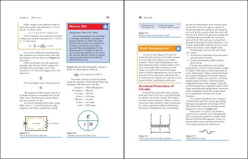
If you have difficulty remembering<br />
this equation in its three forms, the simple<br />
memory device shown in Figure 4-4<br />
may help.<br />
Place your finger over the unknown<br />
quantity and observe what it equals. For<br />
example: Put your finger over E, the<br />
answer is I × R. Put your finger over I, the<br />
answer is:<br />
E<br />
R<br />
Put your finger over R, the answer is:<br />
E<br />
I<br />
The purpose of the memory device is<br />
to make it easier to remember how to use<br />
Ohm’s law. The best way to learn Ohm’s<br />
law is to practice its use.<br />
You must remember that when using<br />
Ohm’s law, E, I, and R must be in volts,<br />
amperes, and ohms, respectively. Study<br />
–<br />
+<br />
E = 6 volts R = 12 ohms<br />
Figure 4-3.<br />
The current equals 0.5 amperes.<br />
History Hit!<br />
Georg Simon Ohm (1787–1854)<br />
Ohm was educated at the University<br />
of Erlangen and became a professor of<br />
physics at Munich in 1849. Ohm developed<br />
the law for which he is best known.<br />
However, it should be noted that he<br />
received little acknowledgment for this<br />
achievement for 20 years. He also did<br />
much pioneering research on the human<br />
ear and how different sounds or frequencies<br />
are broken down by the different<br />
parts of the inner ear.<br />
Figures 4-5 and 4-6. Frequently current is<br />
given in milliamperes, which is:<br />
1<br />
of an ampere or 0.001 A<br />
1000<br />
You must convert to amperes before<br />
using the equation. Studying the following<br />
examples will help you to do this:<br />
1 ampere = 1000 milliamperes<br />
0.5 ampere = 500 mA<br />
0.1 amp = 100 mA<br />
50 mA = 0.05 amp<br />
500 mA = 0.5 amp<br />
10 mA = 0.01 amp<br />
1 mA = 0.001 amp<br />
E<br />
I R<br />
Figure 4-4.<br />
A memory device for Ohm’s law.<br />
38 Electricity<br />
1 milliampere (mA) = 1/1,000 (.001) ampere<br />
1 microampere (mA) = 1/1,000,000 (.000001) ampere<br />
Figure 4-5.<br />
Prefixes used in measuring current.<br />
Math Manipulation!<br />
As you review Figures 4-5 and 4-6,<br />
realize that the powers of 10 make it easier<br />
to work with very large or very small<br />
numbers. These units (milliamperes and<br />
microamperes) make it much easier to list<br />
very, very small units of current. In the<br />
future, we will work with much larger<br />
units. It will be important for you to use the<br />
powers of 10 in electricity and electronics,<br />
so closely review Figures 4-5 and 4-6 as you<br />
examine these mathematics principles.<br />
Overload Protection of<br />
Circuits<br />
It should be quite clear that a certain<br />
kind and size of wire has a specified ability<br />
to conduct an electric current. All conductors<br />
have some resistance. When a current<br />
overcomes this resistance, heat is produced.<br />
If a wire is operated within its limitations,<br />
this heat is dissipated in the surrounding<br />
Basic unit (amp)<br />
10 0 ·<br />
Milliamp (mA)<br />
10 -3 ·<br />
Smaller<br />
Microamp (μA)<br />
10 -6 ·<br />
Figure 4-6.<br />
Conversion chart for ampere prefixes.<br />
air and its temperature does not rise excessively.<br />
However, if too great a current is<br />
forced through the conductor, the temperature<br />
will rise to a point where the wire will<br />
become hot. If the wire gets hot enough, the<br />
insulation that surrounds the conductor<br />
may melt off. The wire may even get hot<br />
enough to melt itself and be destroyed. If it<br />
is near combustible material, such as in the<br />
wall of your home, a fire might result.<br />
Overloading a circuit can occur from<br />
two causes:<br />
1. An excessive load that draws beyond a<br />
safe amount of current.<br />
2. A direct (sometimes called a dead)<br />
short circuit.<br />
Circuits and appliances are usually<br />
protected by a fuse or circuit breaker. A fuse<br />
is simply a thin strip of metal that melts at<br />
a low temperature. Those used in the home<br />
are usually designated 15 and 20 amperes.<br />
(Carefully examine your fuse box or circuit<br />
breaker panel at home. ) Note the Safety<br />
Suggestions later in this chapter. Typically,<br />
circuit breakers have replaced fuses in most<br />
home and industrial applications. However,<br />
older installations may still contain fuses,<br />
or a combination of fuses and circuit<br />
breakers.<br />
If a current exceeds the fuse rating, it<br />
will melt and open the circuit, preventing<br />
damage of equipment and danger of fire.<br />
The symbol for a fuse in electrical circuit<br />
diagrams is shown in Figure 4-7.<br />
Some fuses, of course, are made to<br />
carry heavier currents. You will generally<br />
find a main power panel in a home rated<br />
between 100 and 200 amperes. In fact, as<br />
homes utilize more and more electricity,<br />
even larger amounts of current are<br />
Figure 4-7.<br />
The symbol for a fuse.