Chapter 4 - Goodheart-Willcox
Chapter 4 - Goodheart-Willcox
Chapter 4 - Goodheart-Willcox

You also want an ePaper? Increase the reach of your titles
YUMPU automatically turns print PDFs into web optimized ePapers that Google loves.
This sample chapter is for review purposes only. Copyright © The <strong>Goodheart</strong>-<strong>Willcox</strong> Co., Inc. All rights reserved.<br />
4<br />
Objectives<br />
After studying this chapter, you will be<br />
able to answer these questions:<br />
1. What is the relationship between voltage,<br />
current, and resistance in a circuit?<br />
2. What is Ohm’s law and how can we use<br />
it to solve electrical circuit problems?<br />
3. What types of switches are used in electrical<br />
circuits?<br />
Important<br />
Words and Terms<br />
The following words and terms are key<br />
concepts in this chapter. Look for them as<br />
you read this chapter.<br />
conductive<br />
pathway<br />
control<br />
electrical circuit<br />
load<br />
Ohm’s law<br />
voltage source<br />
The Simple Circuit<br />
Electrical circuits are complete pathways<br />
through which electric current flows.<br />
Three elements are basic to all circuits:<br />
Ohm’s Law<br />
35<br />
1. Voltage source (such as a battery or generator).<br />
A device that supplies the energy.<br />
2. Load (such as a resistor, motor, or<br />
lamp). A device that uses energy from<br />
the voltage source.<br />
3. Conductive pathway (such as an insulated<br />
wire or printed circuit board). A<br />
path from voltage source to load and<br />
back, which carries electrical current.<br />
Circuits usually contain a fourth element,<br />
as well. A control device such as a switch,<br />
fuse/circuit breaker, or relay may be used<br />
to stop, start, and/or regulate the flow of<br />
electricity.<br />
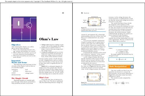
Figure 4-1 is a schematic diagram of a<br />
simple circuit. The symbols show that the<br />
circuit has a battery for the voltage source; a<br />
load device (resistor), which uses the energy<br />
from the voltage source; an “on/off” switch;<br />
and connecting wire to conduct the current.<br />
Ohm’s Law<br />
One of the basic laws of electrical circuits<br />
is Ohm’s law. This shows mathematically<br />
the relationship between voltage (E),<br />
36 Electricity<br />
Source<br />
B<br />
(Battery)<br />
–<br />
+<br />
Connecting wire<br />
E = 6 volts<br />
Control<br />
SW (Switch)<br />
Load<br />
R<br />
(Resistor)<br />
Figure 4-1.<br />
A simple electrical circuit. Note connection of<br />
elements that make up circuit.<br />
current (I), and resistance (R). A thorough<br />
understanding of the use of Ohm’s law will<br />
help you to understand how any circuit<br />
operates.<br />
If you do not completely understand<br />
<strong>Chapter</strong> 2, perhaps now is a good time to<br />
review it once again. You will remember<br />
that an electric current was caused to flow<br />
in a conductor when a force or voltage was<br />
applied to the circuit. Figure 4-1 shows a<br />
simple circuit using a battery as a voltage<br />
or potential difference source.<br />
R represents the resistance in the circuit<br />
and I stands for “intensity” of the current.<br />
E or V represents electromotive force.<br />
As the voltage of battery (B) is fixed<br />
and the resistance of the circuit is fixed, a<br />
definite value of current will flow in the<br />
circuit. (Note the direction of current flow<br />
as indicated by the arrows.)<br />
If the voltage were increased to twice<br />
the value, as in Figure 4-2, then the current<br />
would also increase to twice its former<br />
value. As the voltage increases, the current<br />
–<br />
B E = 12 volts R<br />
+<br />
Figure 4-2.<br />
As voltage is increased, the current increases.<br />
increases. As the voltage decreases, the<br />
current decreases. A mathematician would<br />
say that the current and voltage are in direct<br />
proportion to each other.<br />
The current flowing in these circuits<br />
also depends on the resistance of the<br />
circuit. If we increase the resistance to twice<br />
its value, the current is cut in half. We may<br />
conclude that as the resistance increases,<br />
the current decreases. As the resistance<br />
decreases, the current increases. Again,<br />
mathematically speaking, the current is in<br />
inverse proportion to the resistance.<br />
Georg Simon Ohm, the German<br />
scientist, proved this relationship to be true<br />
in his experiments. The law is named in his<br />
honor. Ohm’s law is stated as:<br />
I =<br />
E<br />
R<br />
where,<br />
I = current in amperes<br />
E = voltage in volts<br />
R = resistance in ohms<br />
By simple algebra, the formula may be<br />
changed to read:<br />
E<br />
R = or E = IR<br />
I<br />
Math Manipulation!<br />
One may readily see that if any two<br />
quantities are known in a circuit, the<br />
third quantity can be found. Referring to<br />
Figure 4-3, notice that values have been<br />
assigned to E and R.<br />
The current is easily computed by<br />
Ohm’s law:<br />
E 6 V<br />
I = or I = = 0.5 A<br />
R 12 Ω
<strong>Chapter</strong> 4 Ohm’s Law 37<br />
If the voltage were unknown and we<br />
knew the current and resistance: I = 0.5 A,<br />
and R = 12 ohms, then:<br />
E = I × R or 0.5 A × 12 Ω = 6 V<br />
If the resistance were unknown and the<br />
voltage and current were given as: I = 0.5 A,<br />
E = 6 volts, then:<br />
E 6 V<br />
R = or = 12 Ω<br />
I 0.5 A<br />
If you have difficulty remembering<br />
this equation in its three forms, the simple<br />
memory device shown in Figure 4-4<br />
may help.<br />
Place your finger over the unknown<br />
quantity and observe what it equals. For<br />
example: Put your finger over E, the<br />
answer is I × R. Put your finger over I, the<br />
answer is:<br />
E<br />
R<br />
Put your finger over R, the answer is:<br />
E<br />
I<br />
The purpose of the memory device is<br />
to make it easier to remember how to use<br />
Ohm’s law. The best way to learn Ohm’s<br />
law is to practice its use.<br />
You must remember that when using<br />
Ohm’s law, E, I, and R must be in volts,<br />
amperes, and ohms, respectively. Study<br />
–<br />
+<br />
E = 6 volts R = 12 ohms<br />
Figure 4-3.<br />
The current equals 0.5 amperes.<br />
History Hit!<br />
Georg Simon Ohm (1787–1854)<br />
Ohm was educated at the University<br />
of Erlangen and became a professor of<br />
physics at Munich in 1849. Ohm developed<br />
the law for which he is best known.<br />
However, it should be noted that he<br />
received little acknowledgment for this<br />
achievement for 20 years. He also did<br />
much pioneering research on the human<br />
ear and how different sounds or frequencies<br />
are broken down by the different<br />
parts of the inner ear.<br />
Figures 4-5 and 4-6. Frequently current is<br />
given in milliamperes, which is:<br />
1<br />
of an ampere or 0.001 A<br />
1000<br />
You must convert to amperes before<br />
using the equation. Studying the following<br />
examples will help you to do this:<br />
1 ampere = 1000 milliamperes<br />
0.5 ampere = 500 mA<br />
0.1 amp = 100 mA<br />
50 mA = 0.05 amp<br />
500 mA = 0.5 amp<br />
10 mA = 0.01 amp<br />
1 mA = 0.001 amp<br />
E<br />
I R<br />
Figure 4-4.<br />
A memory device for Ohm’s law.<br />
38 Electricity<br />
1 milliampere (mA) = 1/1,000 (.001) ampere<br />
1 microampere (mA) = 1/1,000,000 (.000001) ampere<br />
Figure 4-5.<br />
Prefixes used in measuring current.<br />
Math Manipulation!<br />
As you review Figures 4-5 and 4-6,<br />
realize that the powers of 10 make it easier<br />
to work with very large or very small<br />
numbers. These units (milliamperes and<br />
microamperes) make it much easier to list<br />
very, very small units of current. In the<br />
future, we will work with much larger<br />
units. It will be important for you to use the<br />
powers of 10 in electricity and electronics,<br />
so closely review Figures 4-5 and 4-6 as you<br />
examine these mathematics principles.<br />
Overload Protection of<br />
Circuits<br />
It should be quite clear that a certain<br />
kind and size of wire has a specified ability<br />
to conduct an electric current. All conductors<br />
have some resistance. When a current<br />
overcomes this resistance, heat is produced.<br />
If a wire is operated within its limitations,<br />
this heat is dissipated in the surrounding<br />
Basic unit (amp)<br />
10 0 ·<br />
Milliamp (mA)<br />
10 -3 ·<br />
Smaller<br />
Microamp (μA)<br />
10 -6 ·<br />
Figure 4-6.<br />
Conversion chart for ampere prefixes.<br />
air and its temperature does not rise excessively.<br />
However, if too great a current is<br />
forced through the conductor, the temperature<br />
will rise to a point where the wire will<br />
become hot. If the wire gets hot enough, the<br />
insulation that surrounds the conductor<br />
may melt off. The wire may even get hot<br />
enough to melt itself and be destroyed. If it<br />
is near combustible material, such as in the<br />
wall of your home, a fire might result.<br />
Overloading a circuit can occur from<br />
two causes:<br />
1. An excessive load that draws beyond a<br />
safe amount of current.<br />
2. A direct (sometimes called a dead)<br />
short circuit.<br />
Circuits and appliances are usually<br />
protected by a fuse or circuit breaker. A fuse<br />
is simply a thin strip of metal that melts at<br />
a low temperature. Those used in the home<br />
are usually designated 15 and 20 amperes.<br />
(Carefully examine your fuse box or circuit<br />
breaker panel at home. ) Note the Safety<br />
Suggestions later in this chapter. Typically,<br />
circuit breakers have replaced fuses in most<br />
home and industrial applications. However,<br />
older installations may still contain fuses,<br />
or a combination of fuses and circuit<br />
breakers.<br />
If a current exceeds the fuse rating, it<br />
will melt and open the circuit, preventing<br />
damage of equipment and danger of fire.<br />
The symbol for a fuse in electrical circuit<br />
diagrams is shown in Figure 4-7.<br />
Some fuses, of course, are made to<br />
carry heavier currents. You will generally<br />
find a main power panel in a home rated<br />
between 100 and 200 amperes. In fact, as<br />
homes utilize more and more electricity,<br />
even larger amounts of current are<br />
Figure 4-7.<br />
The symbol for a fuse.
<strong>Chapter</strong> 4 Ohm’s Law 39<br />
Safety Suggestion!<br />
If you do look into the power panel of<br />
your home, be careful! Be sure to touch<br />
only the panel door to open it and close it.<br />
Fuses or circuit breakers may have been<br />
removed. This can expose dangerous and<br />
fatal electrical connections! If there are<br />
loose wires or metal conductors exposed,<br />
do not touch the panel. If you are unsure<br />
of the safety of the panel box, leave it<br />
alone. You may want to have a qualified<br />
electrician examine this possibly<br />
dangerous situation.<br />
provided at the main power panel. You will<br />
often find in the electrical service panel in<br />
your home fuses of the cartridge type,<br />
rated for 100 to 200 amperes or more. These<br />
main fuses carry the total current used by<br />
all of the circuits in your home and give<br />
further protection.<br />
In Figure 4-8, a simple load in the form<br />
of a resistor is connected across a voltage<br />
source. If the insulation should become<br />
worn or frayed so that wire A could touch<br />
wire B, the sparks would fly. This is called a<br />
short circuit. This can happen with lamp<br />
and appliance cords.<br />
One improved safety device is called<br />
the circuit breaker. You will study these in<br />
detail in the unit on magnetism. A circuit<br />
breaker is a magnetic or thermal device that<br />
A<br />
Power<br />
Source R<br />
B<br />
Figure 4-8.<br />
A short circuit, sometimes called a direct or<br />
dead short, across the power supply connections<br />
A and B will make the sparks fly!<br />
Safety Suggestion!<br />
If you were to examine the cords to<br />
lamps and appliances at home, it is<br />
possible that you may find a damaged one.<br />
Needless to say, these electrical cords are<br />
dangerous. You can receive a serious burn<br />
from a short circuited lamp cord, as well as<br />
the danger of an electric shock. It is best to<br />
refer these problems to a qualified repair<br />
person and/or electrician.<br />
automatically opens the circuit when an<br />
excessive current flows. See Figure 4-9.<br />
Circuit breakers must be manually reset<br />
before the circuit can be used again. Circuit<br />
breakers have three positions, on, off and<br />
tripped. The tripped position has stopped<br />
current because of an overcurrent condition<br />
(a short circuit or a current above its rated<br />
value). Needless to say, the cause of the<br />
overload should be investigated and<br />
removed or repaired before the current is<br />
turned on again. Circuit breakers are replacing<br />
fuses in most applications in the home<br />
and industry. One reason is because they are<br />
reusable, the fuse is not. As you examine<br />
your home or school electrical service<br />
panels, are fuses or circuit breakers used?<br />
Circuits and Switches<br />
There are many varieties of switches<br />
used in electrical equipment. The student<br />
should be familiar with the common types,<br />
Figure 4-10.<br />
If only one wire or one side of a line is<br />
to be switched, the single-pole, single-throw<br />
Manual Circuit Breaker<br />
Figure 4-9.<br />
Symbol for a circuit breaker.<br />
40 Electricity<br />
Figure 4-10.<br />
Diagrams of switch types.<br />
SPST<br />
SPDT<br />
DPST<br />
DPDT<br />
(SPST) switch is used. If both sides of the<br />
line were to be switched, then a doublepole,<br />
single-throw (DPST) switch would be<br />
used. Reference to Figure 4-10 will show<br />
the circuit diagrams for various switches. If<br />
a single line is to switch first to one point<br />
and then to another, the SPDT switch can<br />
be used. If a double line is to be switched to<br />
two other points, then the DPDT switch<br />
would be used.<br />
Another type of switch used is the pushbutton<br />
switch. These switches can be of two<br />
main types: normally open or normally<br />
closed. The normally opened push button<br />
(PBNO) is found in Figure 4-11. This switch<br />
only completes a circuit when pushed.<br />
Figure 4-12 is the opposite of PBNO, the<br />
normally closed push button (PBNC). This<br />
switch opens the circuit only when pushed<br />
or depressed. Otherwise, the circuit is<br />
closed. The term “normally” is used to<br />
indicate that the push-button switch is at<br />
rest (untouched by someone).<br />
Frequently, it is desirable to switch a circuit<br />
from two different locations. In this case,<br />
a three-way switch is used. Perhaps you<br />
Figure 4-11.<br />
Push button normally open (PBNO).<br />
Figure 4-12.<br />
Push button normally closed (PBNC).<br />
have such switches in your home that permit<br />
you to turn a light on or off from two places<br />
in a room or hallway. The schematic diagram<br />
of this circuit is shown in Figure 4-13.<br />
The light is on, but it can be turned off<br />
by moving either switch 1 or 2. In Figure 4-14<br />
the light is off, but it can be turned on by<br />
either switch 1 or 2. Follow the circuit<br />
through the switches in each position.<br />
In Project 1—Experimenter, Problem 6,<br />
you will gain first-hand experience in connecting<br />
three-way switches, so that lights<br />
can be controlled from different locations.<br />
From main<br />
fuse or circuit<br />
breaker panel<br />
Power<br />
source<br />
At one end<br />
of hallway<br />
3-way<br />
switch<br />
number 1<br />
3-way<br />
switch<br />
number 2<br />
Light in<br />
center of a<br />
long hallway<br />
At opposite end<br />
of hallway<br />
Figure 4-13.<br />
A three-way switch circuit. The light is on.
<strong>Chapter</strong> 4 Ohm’s Law 41<br />
Power<br />
source<br />
3-way<br />
switch<br />
number 1<br />
3-way<br />
switch<br />
number 2<br />
Figure 4-14.<br />
A three-way switch circuit. The light is off.<br />
A common type of switch used in electrical<br />
equipment is the multiple-pole rotary<br />
switch. In this switch, the rotary contact arm<br />
can be connected to one side of an electrical<br />
circuit and the contacts can connect to several<br />
other circuits. By turning the control knob,<br />
any desired circuit configuration can be<br />
used. Multiple switching operations can be<br />
done by mounting several rotary switches<br />
on one control shaft, Figure 4-15. Where<br />
might a switch like this be used?<br />
Quiz–<strong>Chapter</strong> 4<br />
Write your answers to these questions on a<br />
separate sheet of paper. Do not write in this<br />
book.<br />
Draw the circuit diagram for each of the<br />
following problems and compute the unknown<br />
quantities.<br />
1. A circuit has an applied voltage of 100<br />
volts and a resistance of 1000 ohms.<br />
What is the current flowing in the<br />
circuit?<br />
2. A circuit that contains 100 ohms resistance<br />
has a current of two amperes.<br />
What is the applied voltage?<br />
3. A circuit that contains 10,000 ohms of<br />
resistance has a current of 100 mA.<br />
What is the applied voltage?<br />
Figure 4-15.<br />
Multiple-pole rotary switch.<br />
4. A circuit has an applied voltage of<br />
200 volts that causes a 50 mA current<br />
to flow. What is the circuit resistance?<br />
5. An applied voltage of 50 volts causes a<br />
current of 2 amperes to flow. What is<br />
the circuit resistance?<br />
6. A voltage of 500 volts is applied to a<br />
circuit that contains 100 ohms of resistance.<br />
What is the current?<br />
7. If applied voltage is 400 volts and<br />
resistance is 20,000 ohms, what is the<br />
value of I?<br />
8. A meter indicates a current flow in a<br />
circuit of 0.5 amp. The circuit resistance<br />
is 500 ohms. What is the value of E?<br />
9. What applied voltage will cause 500 mA<br />
of current to flow through 500 ohms of<br />
resistance?<br />
10. What applied voltage will cause 10 mA<br />
of current to flow through 1000 ohms<br />
of resistance?<br />
11. An electric appliance has a resistance<br />
of 22 ohms. How much current will it<br />
draw when connected to a 110 volt line?<br />
12. A 110 volt house circuit is limited to<br />
15 amperes by the fuse in the circuit.<br />
The following appliances are connected<br />
to the circuit. Compute the individual<br />
currents for each appliance. What is the<br />
total current flowing in the circuit? Will<br />
the fuse permit this current to flow?<br />
Appliance 1 draws 2 amperes.<br />
Appliance 2 has a resistance of<br />
40 ohms.<br />
Appliance 3 has a resistance of<br />
20 ohms.<br />
42 Electricity<br />
Hands-on experiments are an important part of learning electricity and electronics.<br />
Thousands of different circuits can be created on generic circuit boards. Bus wire<br />
and jumper wire are often used to make connections.